Abstract
This study explores the dynamic behavior of beam induced by bipedal pedestrian traffic and corresponding vibration reducing method by tuned mass damper. Each pedestrian from motion crowd simplifies as a bipedal robot comprised of a lump mass and two massless spring-damping legs. In addition, the tuned mass dampers are installed on the bottom of structure to relieving the vibration of structure. The interactions among pedestrians, tuned mass dampers and structure are considered to establish a governing equation. Research indicates that both the tuned mass damper and pedestrian evidently alter the structural properties of the structure by affecting its frequency and damping capacity. The structure tends to be gently flexible at a lower frequency as pedestrian walk across its surface, but the corresponding damping capacity of the structure is improved. The tuned mass damper always improves both the vibration response and dynamic properties of structure. However, its self-dynamic characteristics of the tuned mass damper tend to deteriorate. The tuned mass damper relieves effectively the lateral vibration in a slender structure than the rigid structure. The change in the mass ratio of tuned mass damper to structure affects significantly the dynamic behaviors of structure. In addition, the layouts of the tuned mass dampers on structure also have remarkable influences on the behaviors. The results of this study provide potential pathways for understanding the vibratory mechanisms of slender structures such as footbridges, grandstands, or stations under crowd excitations.

Highlights
- Both the pedestrian and TMD has significant influences on structural properties such as frequency and damping.
- But the bipedal pedestrian and TMD have very different influences tendencies on changing structural properties.
- The layouts of TMD have remarkable different effects on altering structural responses and properties, especially the single layout on the mid-span position.
1. Introduction
The lateral excessive vibrations of footbridge under crowd excitations have attracted the attention of society of civil engineers, ever since the London Millennium Footbridge accident [1]. Afterwards, the explorations on the human induced lateral waggle on structural responses and properties have been blossomed. The excessive vibrations of structure not only provoke the serviceability problems of these slender structures, but also seriously alter the corresponding dynamic properties. For example, the synchronous walking from motion crowd triggered the lateral excessive swing of M-bridge [2], and crowd motion influences remarkably the natural frequency and damping of structure [3]. To explore the lateral vibrational mechanism of footbridge, some measurements and excitation models have been proposed such as the typical investigation is to identify the lateral excitation forces induced by walking feet. Ricciardelli and Pizzimenti [4] described the lateral excitation forces by the Fourier series from the measurement investigations of a sample with 75 subjects, and recommended the first five values of dynamic load factors. Later, one stochastic model was put forward by Ingolfsson et al. [5], who comprehensively analyzed the lateral forces from single pedestrians during continuous walking on a treadmill. Although, these proposed forcing models are able to well reproduce the lateral excitation, the contributions from walking behaviors and dynamic properties in human body lack considered. A simple inverted pendulum (IP) [6] was further presented to describe pedestrian-structure interaction, and its lateral stability [7] has been extensively researched for seeking out its balance control strategies. Based on the proposed IP model, Carroll et al. [8] introduced it to describe the crowd-bridge dynamic interaction, and it successfully predicted multi-mode instability of the structure. However, uncertainties from the IP application had remained within the model. Bocian et al. [9] presented the probabilistic criteria for lateral stability of bridges under the IP model. A further refine human model has been identified, as well as the suitability of the semi-active biomechanical structure need to be explored. Even later, Yang and Gao [10] studied the lateral vibrational mechanism of footbridge under a bipedal walking robot with a lump mass and two massless spring-damping legs. Later, a simplified theory for structural vibration was proposed based on the assumptions of uniform distribution and synchronized walking of pedestrians [11], which has been used to describe the effect of the change in crowd size on lateral structural damping and the frequency of the structure. Although the lateral vibration of footbridge under walking pedestrian has comprehensively studied, the mechanism of alleviating vibration of structure under bipedal walking is rare explored.
This study presents a lateral vibration theory of structure under the motion bipedal traffic including an absorber that is the tuned mass damper (TMD). The theory considers the interactions among the pedestrian, TMD and footbridge. Firstly, the governing equation constructed including the dynamic contributions of both pedestrians and TMDs. Secondly, numerical examples are used to verify the theory by a rigid and slender footbridge, and the dynamic responses and properties of structure are analyzed. Finally, the effects of TMD parameters on structural dynamic properties are investigated.
2. Theoretical processes
2.1. Governing equations of motion
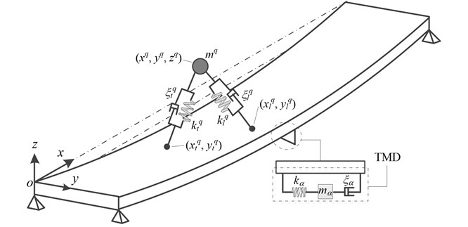
In this model, a three-dimensional space coordinate system is established and its origin locates the left endpoint of footbridge. The corresponding longitudinal, lateral and vertical directions are denoted as x, y and z, respectively. The pedestrian from a crowd is simulated as a bipedal robot system with a lump mass and two massless spring-damper legs (Fig. 1) and it has a single degree-of-freedom in vertical direction. The human body in the qth pedestrian is simplified as a lump mass mq and two mass-less spring-damping legs. The leading leg has the spring stiffness kql and damping ratio ξql, and the corresponding coefficients of the trailing leg are kqt and ξqt, respectively. The leg stiffness with kql and kqt, as well as the leg damping with cql and cqt of the pedestrian are determined according to the axial compression of the both legs [10]. The coordinate position of center of mass (COM) with the pedestrian is (xq,yq,zq). The vertical projection coordinates of leading and trailing feet positions are (xql,yql) and (xqt,yqt), respectively. The TMD with the number of χ are installed in the bottom of deck so as to alleviate the vibration of structure. The lump mass, stiffness and corresponding damping ratio of the αth TMD are mα, kα are ξα, respectively. The structure footbridge is looked as a simply supported beam with the span length L and deck width B. The lateral deflection displacement of structure in longitudinal position x and time point t is w(x,t) and its vertical vibration is negligent in this paper.
The equations of motion governing the vibration of the structure, pedestrian and TMD are derived from the Lagrange equation. The total kinetic energy T and potential energy V of the pedestrian-structure-TMD (PSTMD) system in the double-support phase are defined as:
where ˙xq, ˙yq and ˙zq are longitudinal, lateral and vertical velocities of COM, respectively; Lql and Lqt are the distances from the footholds to the COM of the leading and trailing legs, respectively. Lqo is the leg length in a relaxed condition and g represents the acceleration due to gravity. yα and ˙yα are lateral vibration displacement and velocity of TMD, respectively; wα is the lateral displacement of footbridge at the αth TMD position. ˉm is the mass per meter length of the structure in longitudinal direction and EI denotes its lateral flexible stiffness; w''=∂2w(x,t)/∂x2 means structural lateral curvature.
Fig. 1Mechanical model of pedestrian-footbridge-TMD system
Based on the modal superposition method, the lateral displacement of the footbridge is defined as:
where ϕi(x) is an assumed vibration mode satisfying all boundary conditions, and Yi(t) is the modal coordinate of the structure with the maximum mode number n.
By referencing to the spatial position of pedestrians, the lengths of the leading and trailing legs can be obtained as:
where wql=(xql,yql,t) and wqt=(xqt,yqt,t) are the lateral displacements of footbridge at the points of contact of the leading and trailing feet, respectively.
The total non-conservative virtual work of the PSTMD system is due to the damping force of the footbridge, pedestrian legs and the TMDs; the variation of virtual work is obtained as:
-∫L0cs˙w''δw''dx=∑ni=1QsiδYi+∑Nq=1Qqδzq+∑χα=1Qαδyα,
where cql and cqt are damping of the leading and trailing legs, respectively; cα and cs are the damping of TMD and footbridge, respectively. The terms Qq, Qα and Qsiare the generalized forces of the PSTMD. ˙Lql and ˙Lqt are the axial velocities of the both legs:
-∑nj=1cqyy-ij˙Yj-∑nj=1∑χα=1cαΦi,j(xα)˙Yj-(∫L0cs(ϕ''i)2dx)˙Yi,
where the parametrical terms in Eq. (5) are shown as:
In the above equations, ϕi(x)=sin(iπx/L) is adopted in this study. The Lagrange equations of the PSTMD system are defined as:
Substituting Eqs. (1) into Eq. (7) results in the governing equations of the PSTMD in differential forms as:
-∑Nq=1cqyz-i˙zq-∑χα=1cα-i˙yα+∑nj=1(Kχij-KNδ-ij)Yj-∑χα=1kα-iyα,
where Mi=ˉmL/2 is the modal mass of the structure; ωi and ξi are the ith modal angular frequency and damping ratio of the footbridge, respectively; other parameters in the Eq (8) are shown as following:
KNδ-ij=∑Nq=1kqδ-ij,Kχij=∑χα=1kαΦi,j(xα),kα-i=kαϕi(xα),
kqδl=kql(Lqo-Lql)Lql,kqδt=kqt(Lqo-Lqt)Lqt,kqδ-ij=kqδlΦi,j(xql)+kqδtΦi,j(xqt)
Fi=∑Nq=1(cqxy-i˙xq+cqyy-i˙yq)-∑Nq=1[kqδl(yq-yql)ϕi(xql)+kqδt(yq-yqt)ϕi(xqt)],
Fq=-(cqzx˙xq+cqyz˙yq)-mqg.
The dynamic equations in Eq. (8) can be written in a matrix form as:
where M, C, K, F, ¨U, ˙U and U are the mass, damping and stiffness matrices, and force, acceleration, velocity and displacement vectors, respectively. For the present case, the mass, damping and stiffness matrices, and displace and force vectors can be indicated as:
To understand the governing equation, both damping and stiffness matrices are partitioned as 9 block sub-matrices following the dotted lines. It is noted that the damping and stiffness matrices are time-varying because the pedestrian is position-varying. In the damping matrix of Eq. (11b), the block in 1st row and 1st column includes the contributions from pedestrians and TMDs, which be able to change the damping capacity of structure. The blocks in the 1st row, 2nd and 3rd columns are the pedestrian and TMD damping contributions, respectively. This shows that in theory, the structure can alter the damping capacity of the pedestrians and TMDs in return. The element cqzz in principal diagonal is determined by the position of the COM and the vibration of the structure. Similarly, the stiffness matrix in Eq. (11c) is also time-varying. The block in 1st row and 1st column includes the stiffness contributions from pedestrians and TMDs, which be able to change the flexibility of structure. The elements -kα-i from the block in 1st row and 3rd column are related with the position of TMDs. The elements-kqδl-kqδt in both legs from the block in 2nd row and 2nd column are changing as a result of the movement of the COM and feet. The terms kα from the block 3rd row and 3rd column are stiffness contributions of TMD. Both the damping and stiffness matrices are symmetrical, which needs the lesser computing storage space. It is noted that the pedestrian and absorber are independent both damping and stiffness. This indicates that the vibration of TMD is caused by the pedestrian acting on the structure, and then the structure acting on the TMD, but not the pedestrian acts directly on the TMD. In turn, the effects of TMD on pedestrian are transmitted though the structure.
According to the research from Den [12], the optimized frequency fα and damping ratio ξα of TMD are related with the mass ratio μ=Mα/M1 of TMD to structural modal mass, and it is adopted in this study as:
2.2. Modal analysis
The instantaneous natural frequencies and damping ratios of the PSTMD system can be calculated with the instantaneous mass and stiffness matrices of the system. The instantaneous modal properties of the system are determined with the state-space method [13] as:
The modal properties of the system are determined by solving the eigenvalue problem as:
where λ and ψ are the eigenvalue and eigenvector matrices of matrix A. The ith modal frequency ˜fi and damping ratio ˜ξi can be, respectively obtained for a multi-degrees-of-freedom system as:
where |λi| is the module value, which is positive.
3. Numerical simulation
3.1. Rigid footbridge
A rigid beam with clip supported boundaries [14] is analyzed as an example. Its span length, width and thickness are L=11.0 m, B=1.25 m and h=0.35 m, respectively. The linear density of the beam in longitudinal direction is ˉm= 1363.64 kg/m. The Young modulus of the structural materials is E=3.67X10¹⁰N/m2. The frequency and damping ratio of the bare beam in lateral vibration are respectively 16.1 Hz and 0.3 % respectively. The vertical and torsional vibrational effects of the bridge are neglected in this simulation. A single pedestrian model with the assumed body mass mq=80 kg walks through the structure with the constant velocity of ˙xq=1 m/s. The other parameters of the bipedal model mainly refer the values of Yang and his cooperator [10] as: the step width Lqw= 0.13 m, leg stiffness kqleg=(13.69˙xq+1.587) kN/m and leg damping ratio ξqleg=(4.5˙xq-1.9) %. The COM is assumed swing in lateral direction with a sinusoidal curve with the amplitude of 2.75 cm [15]. The forward walking velocity ˙xqcan be written in the terms of the pacing frequency fqp as ˙xq=fqpLqs; both the pacing frequency and step length Lqs change with the walking speed which is simplified through the empirical relationship Lqs=0.25(fqp)1.86 [16, 17]. The mass ratio coefficient of TMD to structural mode is defined as μ= 0.1.
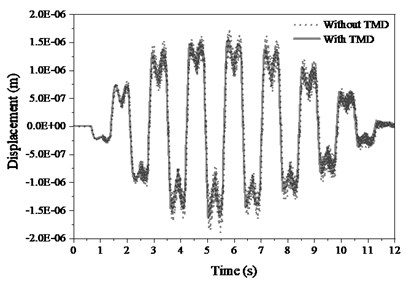
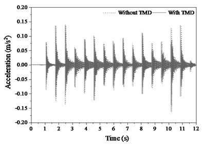
Fig. 2 gives the lateral vibrations both displacement and acceleration in structural mid-span position. When pedestrian walks on the mid-span position, the lateral displacement reaches maximum, but the corresponding acceleration does not. This is due to the structure has a relatively large stiffness in lateral direction and only one single pedestrian produces very fragile excitation. The displacement responses are left-right fluctuated along with the corresponding walking from both feet.
Fig. 2Deflection responses of mid-span
a)
b)
Fig. 3Spectral acceleration of mid-span
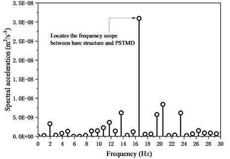
The displacement with TMD is slightly lower than the response without because the TMD absorbs the energy induced by pedestrian excitation. However, effects of TMD on alleviating the acceleration are less effective than the effect on displacement due to too faint excitation from single pedestrian. The spectral density of acceleration in Fig. 3 shows that the main peak occurs on the range between bare structural and PSTMD frequencies instead of walking frequency. Both pedestrian and TMD change distinctly the natural frequency of bare structure. This is due to the action from single pedestrian is too faint to the acceleration of structure fluctuates does not follow the excitation frequency.
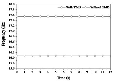
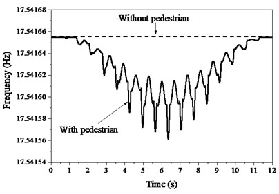
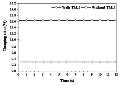
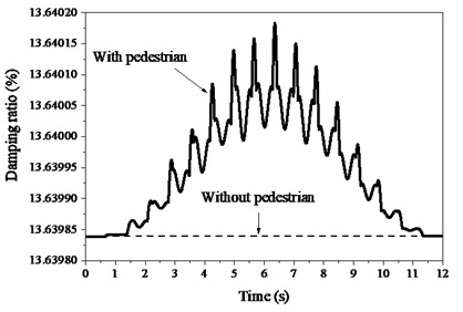
The frequency characteristics of PSTMD system in Fig. 4(a) indicate that TMD increase distinctly the frequency of structure from 16.1 Hz to 17.54 Hz. The frequency details with TMD in Fig. 4(b) show that pedestrian decreases the frequency of structure in contrast. Similarly, the damping characteristics in Fig. 5(a) indicate that TMD also dramatically increases the damping ratio of structure from 0.3 % to 13.64 %, which potentially eliminates the structural vibration. The details of damping ratio with TMD in Fig. 5(b) show that pedestrian only faintly increases the damping ratio of structure. The influences of pedestrian on structural properties are far less than the effects of TMD, because TMD occupies the larger dynamic parameters such as mass and damping.
Fig. 4Instantaneous frequency of structure
a)
b)
Fig. 5Instantaneous damping ratio of structure
a)
b)
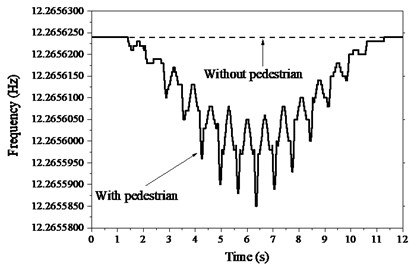
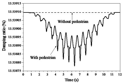
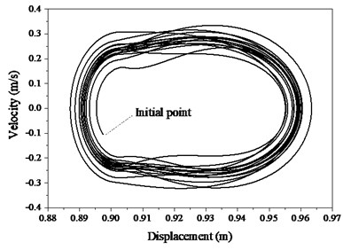
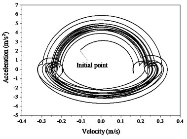
On the contrary, both frequency and damping of TMD decrease respectively from 14.6 Hz and 18.5 % to 12.26 Hz and 13.5 % in Fig. 6 induced by structure. In addition, pedestrian decreases both the frequency and damping ratio of the TMD. As pedestrian walks on the mid-span position, the amplitudes of variations of both frequency and damping ratio reach peaks. The spatial trajectory of pedestrian (Fig. 7) indicates that the COM arrive bottoms as it locates the middle position between both feet. The COM can always keep in harmony with the both feet. To trace the stability of the PSTMD system, the trajectory tracking of the COM in Fig. 8 provides an estimate of the stability of the bipedal model. The circles begin at the starting point and the first circle has the smaller diameter in both figures. Along with an increase in the cycle number, the circles tend to coincide, which shows that the pedestrian in the bipedal model gradually enters a steady walking state. The bipedal pedestrian model exhibits well-stabilized locomotion to simulate a walking pedestrian on the slab.
Fig. 6Instantaneous modal characteristics of TMD
a)
b)
Fig. 7Spatial trajectory of pedestrian COM
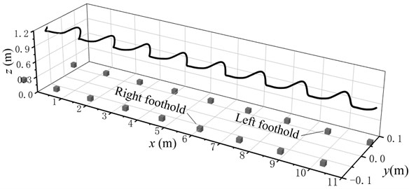
Fig. 8Stable trajectory of pedestrian COM
a)
b)
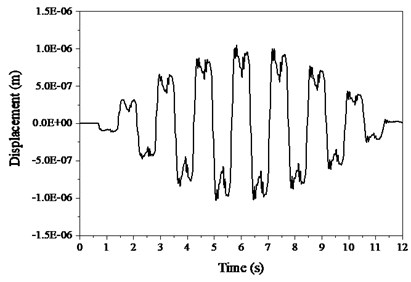
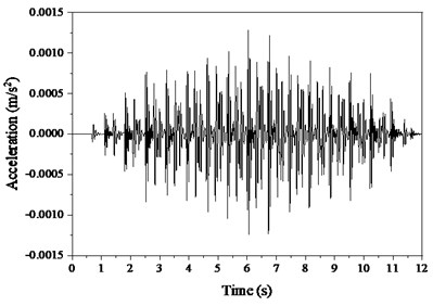
The ground reaction forces from both feet are showed in Fig. 9 and the subfigures (a), (b) and (c) are the longitudinal, lateral and vertical forces, respectively. The shapes of these ground reaction forces are very similar with measurements [18] and this model can well reproduce the ground reaction forces. The vibrational of TMD is plotted in Fig. 10 and its displacement (a) response is left-right cyclically fluctuated following the gait excitation rate of pedestrian. The both displacement and acceleration are far less than the responses of structural mid-span, which indicates the TMD not only help to alleviate the human-induced vibration, but can dissipate energies by the vibration of TMD itself. Moreover, the TMD can remarkably increase the frequency and damping of structure, which improves its dynamic properties.
Fig. 9Ground reaction forces induced by pedestrian

a)

b)

c)
Fig. 10Vibrations of TMD
a)
b)
3.2. Slender footbridge
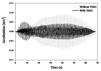
To further explore the effect of vibration attenuation of TMD on a slender structure, the Lardal footbridge [19] with an 80 m of wavelength and 18 tons modal mass is used to simulation. Its first lateral mode frequency is 0.83 Hz, and corresponding damping ratio is 2.5 %. The mass ratio between TMD and structural mode is μ=0.05. The walk velocity is 1.2 m/s and its other gait and leg parameters remain consistent with the previous example. Walk across the footbridge from its left to right ends approximately consumes 68 s.
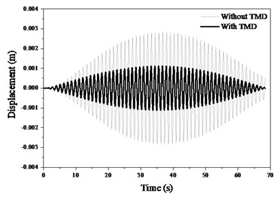
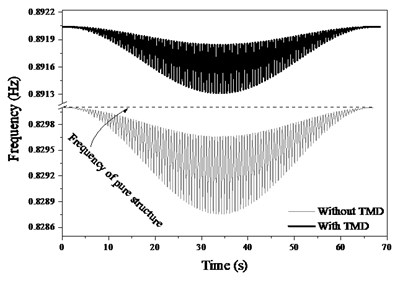
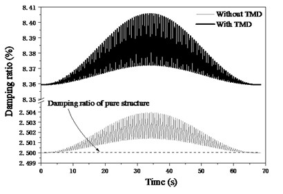
The displacement and acceleration response in mid-span (Fig. 11) show that the TMD is able to dramatically decrease the responses of footbridge. The peak displacement decrease from 2.8 mm to 1.1 mm, and the peak acceleration decreases from 9 cm/s2 to 4 cm/s2. It is also noted that the TMD improves greatly the both frequency and damping of structure (Fig. 12).
Although the pedestrian deteriorates slightly the frequency of structure, the vibration frequency of the footbridge increases from 0.83 Hz to 0.89 Hz showed as Fig. 12(a). In addition, the damping ratio of the footbridge increases from 2.5 % to 8.36 % as Fig. 12(b). Thus, it can be seen that the TMD is able to reduce the pedestrian induced vibration especially in the slender structure.
Fig. 11Dynamic responses of footbridge
a)
b)
Fig. 12Dynamic properties of footbridge
a)
b)
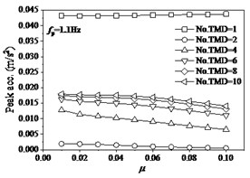
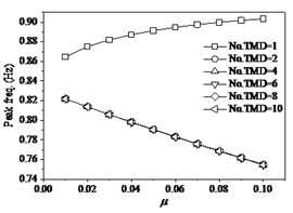
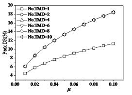
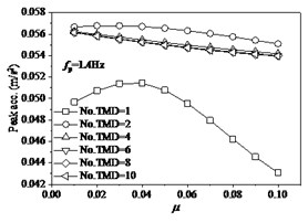
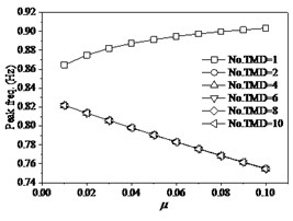
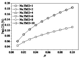
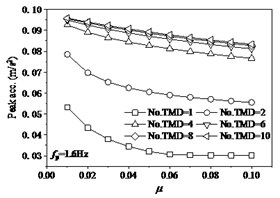
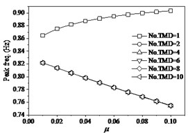
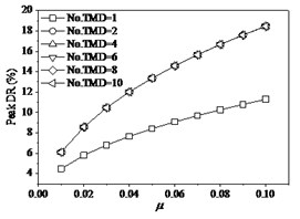
In order to further investigate the effects of the mass ratio μ of TMD to the structure, and the layout number of TMD on structural properties, the each situation with the mass ratio of TMD to structure designs as six layouts with the numbers of TMD 1, 2, 4, 6, 8, 10 and these TMDs occupy the same dynamic properties and uniformly distribute on structure. The effects of mass ratio of TMD to structure indicate that the variations of the mass ratio μor the layout number of TMD have significant influences of structural responses and properties. Research indicates that the single layout of TMD has obvious distinction with the other layouts. When the walking frequency is the lower value of fp=1.1 Hz (Fig. 13), the peak acceleration of mid-span tends slightly to decrease with the increase of μ from 0.01 to 0.1. However, the change of the number of TMD (No. TMD) has the very distinct effects under the same mass ratio of TMD to structure. The peak acceleration reaches minimum as the No. TMD = 2. In addition, the peak frequencies of structure are very different under different the number of TMD layouts. The peak frequency slightly increases with the increase of the mass ratio of TMD to structure under the No. TMD = 1, but the peak frequency decreases with the increase of the mass ratio under the larger number of TMD. And that the change of number of TMD has very faint influences on the peak frequency as the number of TMD is larger than two. The peak DR (damping ratio) of structure always increases with the increase of the mass ratio of TMD to structure under different number of TMD layouts. When the number of TMD is larger than two, the increase of the number of TMD results in the larger peak DR. However, the change of number of TMD has very faint influences on the peak DR as the number of TMD is larger than two. When the walking frequency fp changes as the larger values of 1.4 Hz (Fig. 14) and 1.6 Hz (Fig. 15), the effects of the number of and mass ratio of TMD have similar tendencies on the dynamic properties of structure. When the walking frequency is fp=1.4 Hz (Fig. 14), the peak acceleration of structural mid-span firstly increases then decreases with the increase of the mass ratio of TMD to structure under the No. TMD = 1. The peak acceleration reaches maximum as the μ= 0.03 and No. TMD = 1. However, the larger values of the number of TMD result in the larger peak acceleration, which slightly decreases with the increase of the mass ratio of TMD to structure. When the walking frequency further increases as fp= 1.6 Hz (Fig. 15), the increases of the mass of TMD to structure always cause the decrease of the peak acceleration. However, the peak acceleration decreases with the decrease of the number of TMD layouts. Thus, it can be seen that the less layout of TMD can help restrain the lateral vibration of structure.
Fig. 13The effects of TMD on structure under fp= 1.1 Hz
a)
b)
c)
Fig. 14The effects of TMD on structure under fp= 1.4 Hz
a)
b)
c)
The proposed model has the similar effects on structural properties with other vibration reducing model with TMD [20], which can effectively alleviate the lateral vibration under the appropriate parameters of TMD. This study considers the multi-interaction among pedestrian, TMD and structure, which provide a novel interpretation for pedestrian induced lateral vibration and its corresponding alleviating strategy bring to the civil engineering community. When crowd walk on a slender footbridge with TMD, the effects of the crowd and TMD on structural properties such as damping ratio and frequency would not been omitted. A larger crowd or TMD would significantly alter the dynamic characteristics of the structure, which imply that the past pseudo forces or mass-stiffness-damping replacing walking pedestrian are oversimplified with a practice. The novelties of this study not only consider the contribution from pedestrian stiffness and damping, but also firstly explore the interaction among pedestrian, TMD and structure. In the future, this model can extend to a complicated practical scenario including multi-scale pedestrians and multi-layout TMDs.
Fig. 15The effects of TMD on structure under fp= 1.6 Hz
a)
b)
c)
4. Conclusions
The study explored the lateral vibration of structure induced by pedestrian traffic including the effects of TMD, and interactions among pedestrian, TMD and structure are considered. The TMD increases considerably the frequency of structure, but the pedestrian slightly decrease the frequency. Both the pedestrian and TMD increase the damping capacity of structure, but the effects of pedestrian on structure are very faint. To the rigid beam, the TMD behaves a very inefficient impact on relieving the lateral vibration of structure. However, it can greatly reduce the vibration in the slender structure. In addition, the relieving efficiency on structural vibration is related with the excitation frequency and the mass ratio of TMD to structure. The larger mass ratio tends to alleviate the vibration with the greater capacity. However, the layouts of TMD have significant effects on the alleviating efficiency. When one single TMD installs on the mid-span of structure, the increase of the mass ratio of TMD to structure results in the increase of both the peak frequency and damping ratio of structure. However, the increase of the mass ratio under the larger numbers of TMD causes the decrease of the peak frequency, but the increase of peak damping ratio. In addition, the change of the numbers of TMD has no effects on the both peak frequency and damping ratio. The variations of excitation frequency have no evident effects on changing the structural frequency and damping ratio. It is noted that the bipedal pedestrian and TMD have very different influences on changing structural properties. Therefore, it should be cautious when the pedestrian simplifies as a mass-spring-damping model. This study provides the potential pathways for probing the vibration and corresponding alleviating mechanisms of these structures with human-induced excitation such as footbridges, grandstands, or stations.
References
-
Roberts T. M. Lateral pedestrian excitation of footbridges. Journal of Bridge Engineering, Vol. 10, Issue 1, 2005, p. 107-112.
-
Shun Ichi Nakamura, Toshitsugu Kawasaki Lateral vibration of footbridges by synchronous walking. Journal of Constructional Steel Research, Vol. 62, 2006, p. 1148-1160.
-
James Brownjohn M. W., Paul Fok, Mark Roche, Pilate Moyo Long span steel pedestrian bridge at Singapore Changi Airport – part 1: prediction of vibration serviceability problems. The Structural Engineer, Vol. 17, 2004, p. 21-27.
-
Francesco Ricciardelli, David Pizzimenti A. Lateral walking-induced forces on footbridges. Journal of Bridge Engineering, Vol. 12, Issue 6, 2007, p. 677-688.
-
Ingolfsson E. T., Georgakis C. T., Ricciardelli F., Jonsson J. Experimental identification of pedestrian-induced lateral forces on footbridges. Journal of Sound and Vibration, Vol. 330, 2011, p. 1265-1284.
-
Macdonald J. H. G. Lateral excitation of bridges by balancing pedestrians. Proceedings of The Royal Society A, Vol. 465, 2009, p. 1055-1073.
-
Bocian M., Macdonald J. H. G., Burn J. F. Biomechanically inspired modeling of pedestrian-induced forces on laterally oscillating structures. Journal of Sound and Vibration, Vol. 331, 2012, p. 3914-3929.
-
Carroll S. P., Owen J. S., Hussein M. F. M. A coupled biomechanical/discrete element crowd model of crowd-bridge dynamic interaction and application to the Clifton Suspension Bridge. Engineering Structures, Vol. 49, 2013, p. 58-75.
-
Bocian M., Macdonald J. H. G., Burn J. F. Probabilistic criteria for lateral dynamic stability of bridges under crowd loading. Computers and Structures, Vol. 136, 2014, p. 108-119.
-
Yang Q. S., Gao Y. A. A theory treatment of pedestrian-induced lateral vibration of structure. Journal of Dynamic Systems, Measurement, and Control, Vol. 140, 2018, p. 061004.
-
Dong Y., Gao Y. A., Zhu Y., Zhang P. Simplified theoretical treatment of lateral structural properties under crowd excitation. Mathematical Models in Engineering, Vol. 4, Issue 4, 2018, p. 191-200.
-
Hartog Den J. P. Mechanical Vibrations. Dover Publications, New York, 1947.
-
Juang J. N. Applied System Identification. Prentice Hall, Englewood Clifffs, NJ, USA, 1995.
-
Han H. X., Zhou D. Mechanical parameters of standing body and applications in human-structure interaction. International Journal of Applied Mechanics, Vol. 9, Issue 2, 2017, p. 1750021.
-
Hof A. L., Vermerris S. M., Gjaltema W. A. Balance responses to lateral perturbations in human treadmill walking. Journal of Experimental Biology, Vol. 213, 2010, p. 2655-2664.
-
Ingolfsson E., Georgakis C., Jonsson J., Ricciardelli F. Vertical footbridge vibrations: towards an improved and codifiable response evaluation. 3rd International Conference on Structural Engineering, Mechanics and Computation, 2007.
-
Ingolfsson E. T., Georgakis C. T. A stochastic load model for pedestrian-induced lateral forces on footbridges. Engineering Structures, Vol. 33, 2011, p. 3454-3470.
-
Kei Masani, Motoki Kouzaki, Tetsuo Fukunaga Variability of ground reaction forces during treadmill walking. Journal of Applied Physiology, Vol. 92, 2002, p. 1885-1890.
-
Ingolfsson E. T., Georgakis C. T., Jonsson J. Pedestrian-induced lateral vibrations of footbridges: A literature review. Engineering Structures, Vol. 45, 2012, p. 21-52.
-
Ferreira F., Moutinho C., Cunha A., Caetano E. Use of semi-active tuned mass dampers to control footbridges subjected to synchronous lateral excitation. Journal of Sound and Vibration, Vol. 446, 2019, p. 176-194.
About this article
This research is supported by the National Natural Science Foundation of China (51808247), the Natural Science Research in Jiangsu Colleges and Universities (18KJB560003) and the Opening Foundation of State Key Laboratory of Coastal and Offshore (LP1829), Research on the key technology and application of joint connection of new type prefabricated concrete structure (19KJA430017).

