Abstract
The pitch bearing of the MW-class wind turbine has a weak zone which is not quenched. In the complicated service environment of the wind turbine, the pitch bearing often has breakage accidents in the non-quenching zone. Firstly, this paper takes the pitch bearing as the object and establishes the pitch bearing model with weak zone. Subsequently, the load variation law of the pitch bearing considering non-quenching is analyzed in the four extreme conditions. Finally, the feasibility of the model is proved by comparing the simulation data with the data obtained from the theoretical formula.
1. Introduction
The pitch bearing is an important part of the MW-class wind turbine, and the heat treatment process of the raceway surface is usually quenching. However, the trajectory of the heating head on the raceway cannot overlap (because secondary quenching can lead to cracks), a weak zone will be formed in the non- quenching zone. When the product leaves the factory, the position of the weak zone on the workpiece will be marked with the word “S” to indicate the specific weak zone position.
In the current literature, the research on the failure mechanism of the weak zone of the wind turbine pitch bearing is still rare, and more concentrated on the analysis of the mechanical properties and bearing capacity of the pitch bearing without considering the weak zone of the bearing. In foreign studies, Zupan and Prebil studied the effects of initial contact angle, tightness, clearance value and the stiffness of the support structure on the bearing capacity of the bearing and the actual contact angle [1]. Aguirrebeitia established a mathematical model for carrying capacity of bearing [2]. Alain Daidié analyzed the distribution of contact forces experienced by rolling elements under different loads [3]. In the domestic research, Li Y. F. gave the suggestions for the selection of the parameters of the large-scale pitch bearing [4, 5]; Wang H. used the finite element method to calculate the friction torque of single and double pitch bearings respectively [6]; Mao X. N. verified the strength of the pitch bearing under ABAQUS [7]. In these studies, the influence of the weak zone of the bearing was automatically ignored during the mechanical modeling, and the structural strength and load characteristics of the weak zone were not investigated as the influencing factors during the mechanical analysis.
Therefore, this paper will study the load analysis of pitch bearing considering weak zone.
2. Empirical formula
The maximum contact load calculated by empirical formula is still the main form of design analysis of pitch bearings for most pitch bearing manufacturers at present [8].
When the angular contact radial ball bearing or thrust, bearing is subjected to pure axial force:
When the ball bearing is subjected to pure radial force:
When the two-way thrust ball bearing is subjected to the overturning moment:
The pitch bearing is generally subjected to the combined action of the above three loads. According to the characteristics of the pitch bearing structure itself, the empirical formula of the maximum contact load of the pitch bearing subjected to the combined action of three loads is:
In the formula, the Fa is axial force, the Fr is radial force and the M is the overturning moment; the Dw is diameter of the bearing pitch circle; the Z is number of rolling elements; the α is contact angle.
The design parameters of a pitch bearing are shown in the Table 1.
Table 1A pitch bearing design parameter
Parameter | Data |
Diameter of outer race mounting hole distribution circle D1 / mm | 2000 |
Nominal bore diameter d / mm | 1716 |
Diameter of rolling element center circle Dm / mm | 1900 |
Diameter of inner race mounting hole distribution circle d1 / mm | 1800 |
Nominal outer diameter D / mm | 2080 |
Rolling body diameter Dw / mm | 45 |
Inner channel radius of curvature ri / mm | 23.625 |
Outer channel radius of curvature re / mm | 23.625 |
Ditch row spacing Dc / mm | 80 |
Number of mounting holes N | 54 |
Number of rolling elements Z | 2×120 |
Initial contact angle α / (°) | 45 |
3. Calculation of bearing weak zone by finite element
3.1. Establishment of weak zone model
The hardness of the pitch bearing weak zone is generally around 35 HRC, which is lower than the hardness range of 55-62 HRC in the quenching zone, thus it becomes the weakest zone in the pitch bearing. Looking over the hardness and tensile strength table, the common material elastic modulus, Poisson’s ratio comparison table can get the data in the Table 2.
Table 2Material properties of various parts of pitch bearings
Part | Elastic modulus E (Pa) | Poisson’s ratio μ | tensile strength (MPa) |
Quenching zone | 2.12e+011 | 0.3 | 2180 |
Weak zone | 2.00e+011 | 0.28 | 1125 |
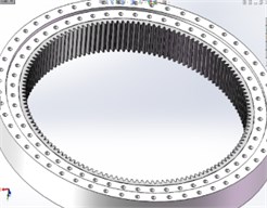
The Fig. 1 shows the finite element analysis geometry model and the physical model of the pitch bearing (without weak zone).
For the establishment of the weak zone of the pitch bearing, the quenching zone and the non-quenching zone are distinguished by establishing a different zone, and then the parameters are set in the material library of the ANSYS WORKBENCH to define the material properties, and the pitch bearing is established (including weak zone) as shown in Fig. 2.
Fig. 1Pitch bearing (without weak zone)
a) Geometric model

b) Physical model
Fig. 2Pitch bearing (with weak zone)
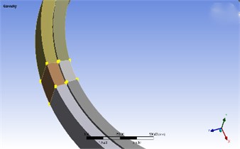
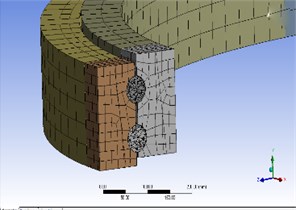
Fig. 3Detail of meshing
3.2. Meshing of weak area
This paper selects the automatic division method. If the geometry cannot be swept, the program automatically generates a tetrahedron, and vice versa produces a hexahedron [9]. Meshing produces a total of 188,054 cells and 355,992 nodes, as shown in Fig. 3.
3.3. Load boundary condition
The pitch bearings are an important part of the wind turbine pitch system. Its outer ring is fixed to the hub, and the inner ring is connected to the blade. According to the actual working condition of the bearing, the outer ring is completely restrained, and the axial load, radial load and overturning moment are applied to the bearing.
The following are the various external loads acting on the pitch bearing under four extreme conditions [10].
Table 3External load under extreme conditions
Design load condition (DLC) | Fa (KN) | Fr (KN) | M (KN·m) |
Extreme running gust | 3599 | 725 | 942.13 |
Extreme turbulence fatigue model | 1764 | 1418 | 2155.28 |
Extreme wind speed model | –252 | 999 | 1297.97 |
Extreme wind shear model | 2053 | 1418 | 2210.64 |
3.4. Contact pair setting
In this paper, a total of 960 contact pairs need to be defined, as shown in Fig. 4. In these contact pairs, the surface of the steel ball serves as a contact surface, and the four raceway surfaces serve as target surfaces.
Fig. 4Contact pair setting

3.5. Simulation result of finite element
From the Eqs. (1)-(4), the force of the pitch bearing under various working conditions can be obtained, as shown in the Table 4.
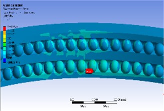
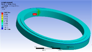
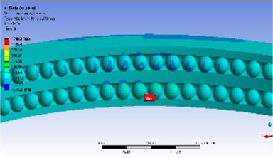
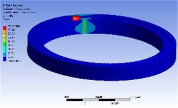
The figure below shows the results of finite element calculation.
Table 4Theoretical load
Working condition | Theoretical value (KN) | Theoretical maximum contact load (MPa) |
Extreme running gust | 41.439 | 1413.26 |
Extreme turbulence fatigue model | 53.843 | 1836.29 |
Extreme wind speed model | 26.390 | 900.02 |
Extreme wind shear model | 56.233 | 1917.80 |
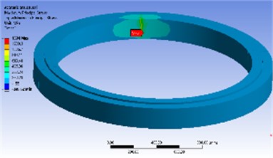
Fig. 5Load on pitch bearing in the first condition
a) Overall load
b) Partial load
Fig. 6Load on pitch bearing in the second condition
a) Overall load
b) Partial load
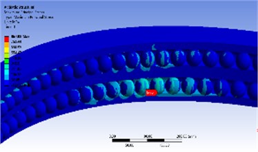
Fig. 7Load on pitch bearing in the third condition
a) Overall load
b) Partial load
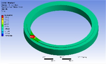
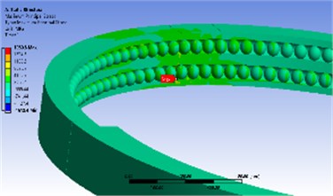
Fig. 8Load on pitch bearing in the fourth condition
a) Overall load
b) Partial load
4. Result analysis
Table 5 shows the deviation of the finite element solution and the theoretical solution. It is easy to see that the error between the finite element value and the theoretical value is less than 5 %.
Table 5Deviation between theoretical value and simulated value
Working condition | Theoretical maximum contact load (MPa) | Finite element maximum contact load (MPa) | Deviation (%) |
Extreme running gust | 1413.26 | 1394.0 | 1.4 |
Extreme turbulence fatigue model | 1836.29 | 1749.3 | 4.7 |
Extreme wind speed model | 900.02 | 867.92 | 3.5 |
Extreme wind shear model | 1917.80 | 1960.6 | 2.2 |
5. Conclusions
1) Results of the finite element and the theoretical value of the empirical formula have a good consistency.
2) According to the comparative analysis of Figs. 5-8, the contact stress at the weak zone of the pitch bearing is larger than the contact stress of the quenching zone. The maximum contact stress is at the contact point between the bottom end and the inner and outer raceways. Moreover, under different working conditions, the load distribution law of the bearing weak zone is also different. Therefore, in the actual installation process, the bearing weak zone should be kept away from the force zone.
3) The simulation analysis of the bearing’s weak zone is a very complicated project. This paper only performs a simple load analysis on the weak zone of the pitch bearing. In the next studies, the bearing capacity and fracture mechanism of pitch bearings with weak zones became an urgent problem to be solved.
References
-
Zupan S., Prebil I. Carrying angle and carrying capacity of a large single row ball bearing as a function of geometry parameters of the rolling contact and the supporting structure stiffness. Mechanism and Machine Theory, Vol. 36, Issue 10, 2011, p. 1087-1103.
-
Aguirrebeitia J., Avilés R., Bustos I. F. D. Calculation of general static load carrying capacity for the design of four-contact-point slewing bearings. Journal of Mechanical Design, Vol. 132, Issue 6, 2010, p. 64-81.
-
Daidié A., Chaib Z., Ghosn A. 3D simplified finite elements analysis of load and contact angle in a slewing ball bearing. Journal of Mechanical Design, Vol. 130, Issue 8, 2008, p. 1188-1188.
-
Li Y. F., Wu Z. Y., Lu B. H. Effect of clearance on load distribution of single-row four-point contact ball slewing bearing. Journal of Mechanical Transmission, Vol. 3, 2010, p. 56-58.
-
Li Y. F. Influence of design parameters of wind power slewing bearing on bearing capacity. Bearings, Vol. 12, 2011, p. 7-11.
-
Wang H., Hu B. C., Chen Y. Finite element analysis and calculation of no-load friction torque of pitch bearing. Bearings, Vol. 2, 2011, p. 1-3.
-
Mao X. Numerical Simulation of Wind Turbine Pitch Bearings. Henan University of Science and Technology, Luoyang, 2012.
-
Wan C. S. Analytical Method of Rolling Bearing. Mechanical Industry Press, Beijing, 1987.
-
Maimaitiming A. N., Chen H. L. Introduction and Application of Finite Element Analysis of ANSYS Workbench18.0. Mechanical Industry Press, Beijing, 2018.
-
Chen L., Yan J. F. Calculation and analysis of working load of pitch bearing. Harbin Bearing, Vol. 32, Issue 4, 2011, p. 1-6.
About this article
Financial support from National Natural Science Foundation of China (51575178), financial support from Hunan Natural Science Foundation of China (2018JJ2120).

