Abstract
The problem of simulation of moving load effect on bridges is a relatively old problem. It was induced by the collapse of the Chester Rail Bridge in England in the year 1847 and can be traced in the literature since the year 1849. The new generation of young research workers is capable to contribute to the solution of the problem with new findings. The contribution is devoted to the modeling of the vehicle motion along a two-span bridge in the environment of the program system ADINA. The task is solved as a plane problem. It described the creation of a discrete computational model of vehicle with 8 degrees of freedom. The bridge is modeled using beam elements. It is assumed that the vehicle enters the bridge already vibrant. The vehicle and bridge response is modeled when vehicle driving at the speed of 70 km/h. The time course of oscillation of vehicle model's characteristic points and the oscillation of mid spans of individual bridge fields are shown graphically. Important results are given in numerical form. The Newmark's method is used for the solution of equations of motion.
1. Introduction
The problem of simulation of moving load effect on bridges is a relatively old problem. It was induced by the collapse of the Chester Rail Bridge in England in the year 1847 and can be traced in the literature since the year 1849 [1, 2]. In Czech and Slovak Republic there is the deep tradition in modeling of moving load effect on transport structures. The works of authors as V. Koloušek [3] and L. Frýba [4] obtained world acknowledgement. The monographs [5] and [6] are especially dedicated to the dynamic of railway and highway bridges. Development and research in this area is continuing to these days. While the problem of dynamic of railway bridges was studied since the year 1847, the problems of dynamic of highway bridges start to be studied only in the 20th century. The 1st important report on this topic was published by the American Society of Civil Engineers [7]. The complete review of the results of solution till the year 1975 was published by Tseng Huang in [8]. The new generation of young research workers is capable to contribute to the solution of the problem with new findings [9-12]. Numerical modelling of the vehicle motion along a bridge structure requires to pay attention minimally to these facts: creation of computing models of vehicles, creation of computing models of bridges, creation of computing programs for solution of equations of motion and displaying of obtained results. The contribution is devoted to the modeling of the vehicle motion along a two-span highway bridge in the environment of the program system ADINA. It described the creation of a discrete computational model of vehicle and a bridge. The time course of oscillation of vehicle and bridge are shown graphically. Important results are given in numerical form.
2. Computational simulation
2.1. Model of a vehicle
In ADINA system is vehicle modelled using mass points, which are interconnected by linear elastic spring elements and elements of beam type. Beam elements have a high bending stiffness to replace their infinitely rigid links with their parameters. However, their mass does not consider to the calculation. Tires and body suspension are replaced by linear spring elements, which take account of viscous damping. For the physical description of the vehicle model, is thus a combination of spring, mass and beam elements.
2.2. Model of a two span bridge
Planar models of a bridge are often used in practical engineering tasks. From the FEM point of view, the bridge id modelled from beam elements. This bridge from beam elements is statically managed as a continuous beam. These are planar beam elements with four degrees of freedom and we do not consider the effects of normal and torsional load effects. Since the numerical simulation is only considered with a vertical load, this type of beam element is very suitable.
2.3. Computational simulation of a plane model a vehicle and two span bridge
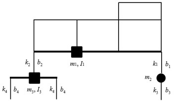
Numerical simulation represents the passage of a vehicle along the bridge with a smooth surface of road profile. For the passage of the vehicle along the bridge, the vehicle has been granted non-zero initial conditions. Therefore, the interaction of the inertial forces of both systems can be monitored. In numerical simulation, the time step is 0.001 s. The vehicle speed is constant during passing along the bridge and its speed is 70 km/h. Modeling also took into account the necessary area for acceleration and deceleration of the vehicle. It was modeled as a rigid surface before and behind the bridge construction. The bridge has a length of 60 meters and is constructed from two 30 m span. The Newmark’s method is used for the solution of equations of motion.
Fig. 1Numerical simulation model scheme

3. Numerical solution
For the numerical solution of the vehicle – bridge interaction were used following input data: k1= 287433 N/m, k2= 1522512 N/m, k3= 2550600 N/m, k4=k5= 5022720 N/m, b1= 19228 kg/s, b2= 260197 kg/s, b3= 2746 kg/s, b4=b5= 5494 kg/s, m1= 22950 kg, m2= 910 kg, m3= 2140 kg, I1= 62298 kg∙m2, I3= 932 kg∙m2, a= 3.135 m, b= 1.075 m, s= 4.210 m, c= 0.660 m, and initial condition: r1(0)= –0.021 m, ˙r1(0)= 0.0 m/s, r2(0)= 0.003535 rad, ˙r2(0)= 0.0 rad/s, r3(0)= –0.0035m, ˙r3(0)= 0.0 m/s, r4(0)= –0.0026 m, ˙r4(0)= 0.0 m/s, r5(0)= 0.00 rad, ˙r5(0)= 0.0 rad/s.
Bridge input data and initial conditions: μ= 19680.0 kg/m, b×h= 11×1.38 m2, I= 2.4 m4, E= 3.85e10 N/m2, w1(0)= 0.0 m, ˙w1(0)= 0.0 m/s, w2(0)= 0.0 m, ˙w2(0)= 0.0 m/s;
Fig. 2Scheme of the vehicle numerical parameters
4. Results and discussion
4.1. Result of numerical simulation
For the numerical simulation of vehicle motion on a two span bridge, 5 interest points were analyzed. These points are: These points are in the Fig. 1 labeled from 1 to 5 and they are located: in the middle of the 1st span bridge (1), in the middle of the 2nd span bridge (2), center of gravity (3) on the vehicle, front axle (4) and rear axle (5) on the vehicle. The results of the vertical deflection these 5 interest points are presented in the Fig. 3 to Fig. 7.
Fig. 3Vertical bridge deflection in the middle of the 1st span, point Nr.1
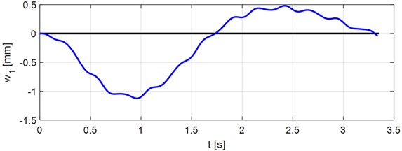
Fig. 4Vertical bridge deflection in the middle of the 2nd span, point Nr.2
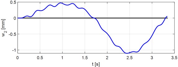
Fig. 5Vertical vehicle deflection in the center of gravity, point Nr.3
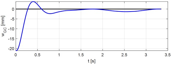
Fig. 6Vertical vehicle deflection in the front axle, point Nr.4
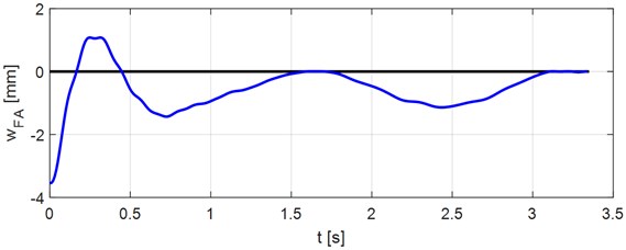
Fig. 7Vertical vehicle deflection in the rear axle, point Nr.5
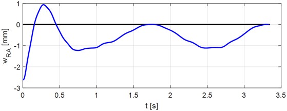
As numerical simulation outputs are interesting the result of maximal vertical deflection of the bridge in the point Nr. 1 are w1,max= –1.12345 mm in time t1,max= 0.960 s, and minimal vertical deflection are w1,min= 0.479965 mm, in time t1,min= 2.420 s. Then in the point Nr. 2 are maximal values w2,max= –1.10305 mm, in time t2,max= 2.440 s and minimal values w2,min= 0.474085 mm, in time t2,min= 0.960 s.
4.2. Experimental validation
Experimental measurement response of the bridge structure during vehicle passage is very important due to the verification of algorithms and numerical simulation. The experiment on the bridge construction is planned in the future, and its role will be realistic to know the shapes of the response functions of the time and frequency domain. Experimental measurements on the vehicle have already been implemented, and the measurement consisted of modal analysis of the vehicle and determination of its natural modes of vibration [13]. Experimental measurement in labo was also accomplished on a bridge construction constructed on a model scale, where the numerical simulation results were confirmed [14].
5. Conclusions
Numerical modeling of the problems of vehicle and bridge interaction is an effective tool for the solution of real tasks of engineering practice. The innovative contribution in solving vehicle-bridge interaction is modeling of the vehicle in combination with mass, damping and stiffness parameters, which can better describe the real vehicle and its movement along the bridge construction. Quality of obtained results is dependent on the quality of input data. The present state of computing technique enables the numerical processing of solved problems in real time. From the practical point of view the influence of various vehicle and bridge parameters is interested. The results obtained from numerical analyses are used in the process of design of optimal bridge parameters with respect to lifetime and reliability of the bridge structure [15].
References
-
Willis R. Report of the Commissioners Appointed to Inquire into the Application of Iron to Railway Structures. Stationary Office, London, 1849.
-
Stokes G. G. Discussion of a Differential Equation Relating to the Breaking of Railway Bridges. Transactions Cambridge Philosophic Society, 1849, p. 707.
-
Koloušek V. Dynamics in Engineering Structures. Academia, Prague, 1973, p. 580.
-
Frýba L. Vibration of Solids and Structures under Moving Load. Academia, Prague/Noordhoff International Publishing, Groningen, 1972, p. 484.
-
Frýba L. Dynamics of Railway Bridges. ACADEMIA, Prague, 1992, p. 325, (in Czech).
-
Melcer J. Dynamic Calculations of Highway Bridges. EDIS, Žilina, 1997, p. 287, (in Slovak).
-
Impact on Highway Bridges. Final Report of the Special Committee on Highway Bridges. Transactions ASCE, Vol. 95, 1931, p. 1089-1117.
-
Huang T. Vibration of bridges. Shock and Vibration Digest, Vol. 8, Issue 3, 1976, p. 61-76.
-
Valašková V., Melcer J. Some possibilities of modeling of moving load on concrete pavements. Journal of Measurements in Engineering, Vol. 6, Issue 4, 2018, p. 203-209.
-
Shi X. M., Cai C. S. Simulation of dynamic effects of vehicles on pavement using a 3D interaction model. Journal of Transportation Engineering, Vol. 135, Issue 10, 2009, p. 736-744.
-
Buhari R., Rohani M. M., Abdullah M. E. Dynamic load coefficient of tyre forces from truck axles. Applied Mechanics and Materials, Vol. 405, Issue 408, 2013, p. 1900-1911.
-
Zaki N. Dynamic response of highway bridges to moving vehicles considering higher modes. Journal of Engineering and Applied Sciences, Vol. 56, Issue 1, 2009, p. 21-38.
-
Melcer J., Lajčáková G., Valašjová V. Moving load effect on concrete pavements. Wydawníctwo Towarzystwa Slowaków w Polsce, Kraków, 2018.
-
Melcer J. Experimental verification of an assumption. Proceedings of the 52nd International Scientific Conference on Experimental Stress Analysis, Czech Republic, 2014.
-
Čecháková V., et al. FEM modeling and experimental tests of timber bridge structure. Procedia Engineering, Vol. 40, 2012, p. 79-84.

