Abstract
This paper provides the formulation of the problem of forced vibrations of structures, which has the following peculiarities: equations of motion are formulated in absolute coordinates allowing to take into account the asynchronous excitations of the supports, smoothing of the time functions for forced displacements with the help of Hermite polynomials, and also the possibility of considering damping that does not obey the Rayleigh hypothesis.
1. Introduction
In the classical formulation of the seismic problem, the motion of the finite element design model is considered in the coordinate system associated with the mobile rigid platform supporting the entire structure (Fig. 1).
Fig. 1The classical formulation of a seismic problem
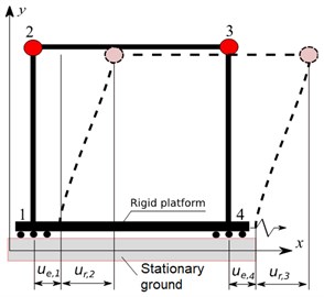
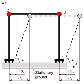
Fig. 2The formulation of a seismic problem in absolute coordinates
The equations of motion are written as follows:
here , , are mass, dissipation and stiffness matrices respectively, is the displacement vector, the subscript denotes the components of the bulk motion – movement of the platform points with respect to a fixed coordinate system . Components of the relative motion – movement of the points of the structure with respect to the mobile platform, denoted by the subscript , are the unknowns. The input action is the given accelerogram .
In the case of the asynchronous excitation of the supports the equations of motion are written as follows [1]:
where are the displacements of nodes of the design model in the absolute coordinate system fixed to the stationary ground, are the displacements with respect to the quasistatic state , determined by solving the problem:
In Eqs. (2) and (4) and are stiffness and mass submatrices corresponding to the degrees of freedom for which the accelerations are given. As a rule, the problems Eqs. (1) and (2) are solved by the method of expansion in natural modes determined for a structure with fixed supports ( 0). In order to separate the equations of motion Eqs. (1), (2) into unrelated equations in normal coordinates, the dissipation matrix has to be represented as a linear combination of the mass and stiffness matrices, i.e. the Rayleigh hypothesis has to be fulfilled. However, in the case of multi-component damping, when different structural elements are made of materials with different damping, and also in the case of local dampers, the application of this approach causes significant difficulties.
Moreover, the approach Eq. (2) in the case of an asynchronous excitation of supports requires an additional solution of the quasistatic problem Eq. (4) with subsequent superposition Eq. (3) of solutions of the dynamic and static problems, which substantially complicates the solution procedure.
The equations of motion are written in absolute coordinates in SCAD [2], (Fig. 2), which provides the natural solution of the problem of forced vibrations at the asynchronous excitation of supports both in the case of the Rayleigh damping and the multi-component damping, and in the case of the local dampers as well. The proposed formulation of the problem is presented in this paper.
2. Problem formulation in absolute coordinates
The equation of motion (Fig. 2) has the form:
where the subscript corresponds to the specified displacements, velocities and accelerations of the bulk motion, and is the vector of the external forces of the finite element design model. In the case of the seismic action 0. It follows from Eq. (5) that:
The left-hand side Eq. (6) contains displacements, velocities and accelerations that have to be determined, and the right-hand side expression contains known displacements and velocities. All components of the displacement, velocity and acceleration vectors are given in the absolute coordinate system fixed to the stationary ground. Dissipation matrix blocks and are assembled in exactly the same way as the stiffness matrix blocks and , using a standard assembly procedure covering the finite elements of the design model [3]. It is stated in [1] that the term in Eq. (6) can be neglected. However, we will keep this term for the sake of precision. In the proposed approach the input signal is not an accelerogram, as is in the case of the classical approach described by Eqs. (1) and (2), but a vibrogram and a velocigram . Therefore, the given accelerogram must be integrated twice, using the Accelerogram Editor from SCAD Office [2].
If Eq. (6) is complemented with the initial conditions (usually accepted: 0), we obtain the Cauchy problem. The direct implicit – HHT method [4] is usually used for its numerical integration.
3. Smoothing of forced displacements
Let’s consider the problem of vibrations of a linear oscillator excited by a given displacement of the support (Fig. 3).
Fig. 3The linear oscillator with a rigid link
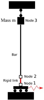
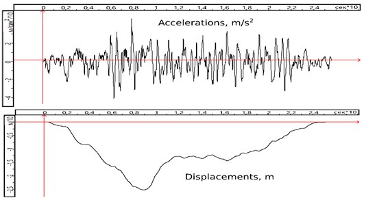
Fig. 4The given acceleration and displacement in the node 1
A peculiarity of this problem is modeling a rigid link connecting nodes 1 and 2 using the method of penalty functions [5]. This approach is widely used in SCAD and has a number of advantages over the traditional method of accounting for rigid links, based on kinematic and static relationships of structural mechanics. The physical essence of the method of penalty functions is equivalent to setting springs, the stiffness of which is several orders of magnitude greater than the stiffness of the finite elements adjacent to the nodes connected by a rigid link. In the exact solution of this problem, the horizontal displacements, velocities, and accelerations of the node 2 must be exactly equal to the respective displacements, velocities, and accelerations of the node 1.
The Newmark method is used for the numerical solution (the parameter in the – HHT method is taken as zero). Displacements of the nodes 1 and 2 turn out to be practically equal, the velocities differ insignificantly, and the horizontal acceleration of the node 2 is completely distorted by the high-frequency component (Fig. 5), which appeared due to the high stiffness caused by the application of the penalty function method in the modeling of a rigid link. It should be noted that the displacements, velocities and accelerations of the node 3, as well as the forces and bending moments in the bar are obtained correctly.
Fig. 5Acceleration in the node 2. High-frequency component distorts the solution
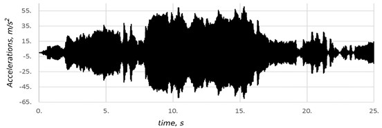
The reason for the distortion of the acceleration in the node 2 was the application of the linear interpolation to approximate the time function of the given displacements of the node 1. The velocity-time relationship is represented by a piecewise constant function with discontinuities at the interpolation nodes (Fig. 6). Accelerations between the interpolation nodes are zero, and those at the nodes are represented by Dirac delta functions.
Fig. 6Approximation of the displacements, velocities, and accelerations when using the linear interpolation for the given displacements
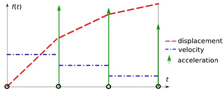
While the linear interpolation was used to approximate the time function for the external forces , the inertial properties of the design model were smoothing the jumps shown in the Fig. 6. In the classical approach to seismic problems Eqs. (1) and (2), the input action is a given acceleration, so applying the linear interpolation to the time function for accelerations also does not lead to the excitation of high-frequency components.
In order to eliminate parasitic high-frequency oscillations arising in the proposed approach Eq. (6) when using forced displacements and velocities as input, we apply Hermite polynomials for the interpolation of forced displacements between the nodes:
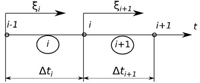
where , , , , , are the displacements and velocities in the interpolation nodes and (Fig. 7). The superscript over the displacement denotes the interval number, which is circled in the Fig. 7. Therefore, here . It follows from Eq. (7) that:
This approach provides the absence of discontinuities of the displacements and velocities in the interpolation nodes:
The values of the displacements in the interpolation nodes are given, and the values of the velocities are not. Our task is to select such nodal values of the velocities so that there are no discontinuities in the accelerations in the nodes:
Applying Eq. (11) to each internal interpolation node and supplementing it with the boundary conditions 0, where is the number of the last point where the displacements are specified, we obtain a system of linear algebraic equations with a tridiagonal symmetric matrix, solving which, we determine the values of the velocities , 1, 2, …, at the interpolation nodes.
Fig. 7Interpolation nodes and local coordinates
As a result of applying the proposed approach based on the interpolation of forced displacements by Hermite polynomials, the horizontal acceleration of the node 2 turned out to be exactly the same as the horizontal acceleration of the node 1 (Fig. 4).
4. Asynchronous excitation of supports
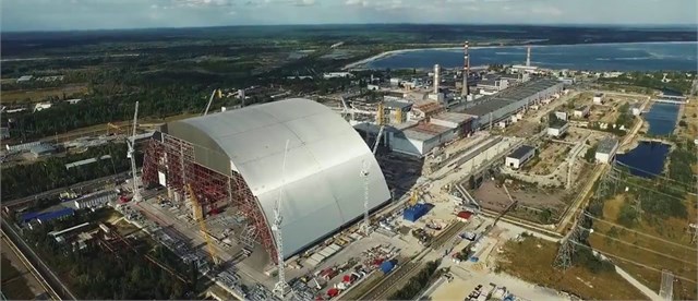
If a structure has a considerable length, it becomes necessary to take into account the fact that the excitations in the soil reach some supports before the others ([7], [8] and so on). Fig. 8 shows the general view of the New Safe Confinement over the fourth power unit of the Chernobyl nuclear power plant, Fig. 9 shows the design model created in SCAD, and Fig. 10 shows an accelerogram of the input action [6].
Fig. 8The new confinement “Arka” before the sliding over the old confinement, covering the damaged structures of the fourth power unit of the Chernobyl nuclear power plant
According to the geophysical surveys [6], the velocity of the seismic wave propagation is 200-300 m/s, and the predominant period of ground vibration is 0.4 s. Thus, the seismic wave length lies in the range 80-120 m. When the seismic wave propagates along the axis, the delay time of the wave arrival at the distant support is / 0.86-1.29 s, i.e. (2.14-3.2)∙.
The Rayleigh damping model is used. According to recommendations [6], the factor for the mass matrix is assumed to be 0.16, and the factor for the stiffness matrix is 0.01.
Fig. 9The design model. The red arrow depicts the direction of a seismic input motion
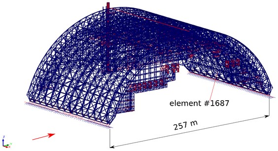
Fig. 10Accelerogram of the input motion
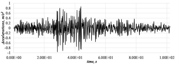
Fig. 11 shows the longitudinal force-time relationship in the element #1687 (Fig. 9), of the bottom chord of the middle arch truss. This element turned out to be one of the most loaded structural elements under the seismic action.
Fig. 11The longitudinal force in the element #1687, t0= 0 – synchronous excitation, t0= 1.2 s – asynchronous excitation
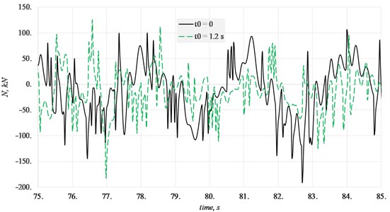
The delay in achieving a seismic excitation of a distant support leads to a significant change in the longitudinal force-time relationship. Fig. 11 shows a time interval, where the longitudinal force reaches its largest absolute values. Although the maximum absolute values at 0 and 1.2 s differ insignificantly in this example, the character of these relationships are completely different, and as a result the maximum force values are reached at different moments in time.
5. Multi-component damping
Fig. 12 shows a design model of the spatial frame, the lower two floors of which are made of reinforced concrete (/ 0.1, is the coefficient of internal inelastic resistance, is the logarithmic decrement of oscillations), and the upper two floors are made of steel ( 0.03). Soil compliance in the direction of the translational displacements is modeled by the springs with stiffness 10 MN/m, installed in the level of the supports, and the soil dissipation is modeled by local dampers with viscosity 10 MN∙s/m. The oscillations are excited by the synchronous movement of the supports in the direction of the axis, and the time function is taken as , where the frequency of the forced oscillations is , and is the second natural frequency of oscillations, at which the structure moves mainly in the direction of the ground excitation.
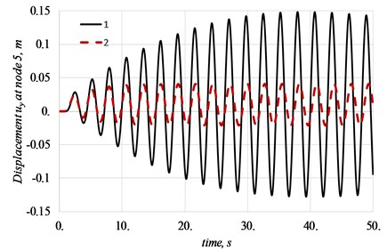
Since the seismic action takes the structure through all the resonance modes, we set such a testing load so as to create the resonance conditions. The only factor limiting the resonance amplitude of the oscillations of the linear design model is damping. Therefore, it is very important to take into account the damping correctly under seismic actions. Curve 1 (Fig. 13) describes the horizontal displacements of the node 5 in the direction of load action when only local dampers modeling the soil dissipation are taken into account, and curve 2 describes them in the case when both the soil dissipation and damping in structural elements are taken into account.
It should be noted that a dissipation model not corresponding to the Rayleigh hypothesis was used when solving this problem. The dissipation matrix for column and beam finite elements is determined as follows:
where , are dissipation and stiffness matrices of the finite element , is the coefficient of internal inelastic resistance of the material.
Fig. 12Design model for a reinforced concrete and steel spatial frame
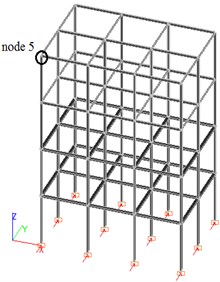
Fig. 13Horizontal displacement of the node 5. 1 – only local dampers, 2 – local dampers and material damping
6. Conclusions
The presented formulation of the problem of forced structural vibrations enables to solve problems for large span structures that require the consideration of the asynchronous excitation of supports and to consider both the Rayleigh damping model and the material dumping, that allows one on the creation of the design models with multi-component damping. It is shown that with the forced excitation of supports, linear interpolation of displacements in time can lead to the appearance of parasitic high-frequency oscillations. A method for constructing a local cubic approximation based on the use of shape functions in the form of Hermite polynomials, which does not lead to the above-mentioned high-frequency oscillations, is also proposed.
References
-
Clough R. W., Penzien J. Dynamics of Structures. Computers and Structures Inc., Berkeley, CA, USA, 2003.
-
Karpilovskyi V. S., Kryksunov E. Z., Maliarenko A. A., Perelmuter A. V., Perelmuter M. A., Fialko S. Y. SCAD Office. Version 21, System SCAD++, SCAD Soft, 2018, https://scadsoft.com/download/SCAD1033.pdf.
-
Zienkiewicz O. C., Taylor R. L. The Finite Element Method. Fifth Edition, Vol. 2, Solid Mechanics, Butterworth – Heinemann, 2000.
-
Miranda I., Ferencz R. M., Hughes T. J. R. An improved implicit-explicit time integration method for structural dynamics. Earthquake Engineering and Structural Dynamics, Vol. 18, 1989, p. 643-653.
-
Fialko S. Y. Application of rigid links in structural design models. International Journal for Computational Civil and Structural Engineering, Vol. 13, Issue 3, 2017, p. 119-137.
-
Seismic Micro Districting of the Chernobyl NPP Industrial Site and Seismic Monitoring of the Shelter Facility. Report S. I. Subbotin Institute of Geophysics. NAS of Ukraine, Kiev, 1995-1996, (in Russian).
-
Dulińska J., Zięba A. Dynamic response of pipelines to non-uniform kinematic excitation. Technical Transactions, Civil Engineering, 2005, p. 3-21.
-
Zembaty Z. Vibrations of bridge structure under kinematic wave excitations. Journal of Structural Engineering, Vol. 123, Issue 4, 1997, p. 479-488.
