Abstract
Ultrasonic vibration has been found to play a significant role in promoting surface nano-crystallization of sapphire in a liquid aluminum bath. And the distribution of the vibration field is critical in controlling the modification procedure. Here, distribution of the ultrasonic vibration in a liquid aluminum bath was investigated by finite element method (FEM). Effects of shape of the ultrasonic horn and distance between the horn and the sapphire plates were investigated. It was found that the ultrasonic vibration density is high in the area adjacent to the ultrasonic horn. The distance between the horn and the plates significantly influence the vibration distribution. And the vibration density decreased significantly at the liquid/solid interface, indicating obvious energy absorption there. Vibration energy grads can be formed on sapphire surface. And this phenomenon shall be used to achieve different aims.
1. Introduction
Monocrystalline α-Al2O3 is usually named as sapphire. It has many good properties, for example, high strength, significant corrosion resistance and excellent light transmittance. Soldering of sapphire is highly desired in many industries to fabricate devices [1-4]. Soldering process basically involves melting a metal as a “glue” to stick the base materials together. But wetting and bonding between metals and sapphire are poor due to the significant difference in physical and chemical natures between them.
Ultrasound was found to be very effective to promote wetting and bonding in the typical soldering process. Kolenak et al soldered Al2O3 ceramics with a Sn-Ag-Ti alloy with an ultrasonic soldering method [5, 6]. In our previous works, ultrasound has been used to build nano-crystalline layers in aluminum melt alloys, which can significantly benefit the wetting and bonding between the sapphire and liquid alloys [7, 8].
One key procedure in the ultrasonic treatment of sapphire is the ultrasonic dipping, in which ultrasonic vibration distribution is the essential issue. The locations with higher vibration density are expected to be treated more effectively. Thus, it is very important to know the vibration density field, so that fine control of the procedure can be achieved. However, since it is very difficult to directly measure the ultrasonic vibration distribution, knowledge in this aspect is still far from abundant.
In this study, finite element method (FEM) was used to identify the characteristics of ultrasonic vibration in a liquid aluminum bath. Distribution of the vibration density was investigated in three conditions. This can provide useful reference for ultrasonic vibration-assisted materials treatment.
2. Models and methods
The simulation was carried out by using COMSOL Multiphysics. The model used in this study is shown in the Fig. 1. The bath was 140 mm high. Diameters on the bottom and the top was 140 and 180 mm. The diameter of the cylindrical ultrasonic horn was 20 mm, 30 mm and 40 mm. The merging depth of the horn was 20 mm. Cylindrical sapphire plates were placed beneath the horn. The diameter was 100 mm, and the thickness was 20 mm. Sound velocity of the liquid aluminum and sapphire was as 912 m/s and 10835 m/s, and the density of them was 2.7 kg/cm3 and 4 kg/cm3. Since the 3D model can require a large amount of calculation, and it is actually axisymmetric, an 2D model was used to replace the 3D model.
The input power of the ultrasonic horn was set as 200 w, 500 w and 800 w. Distance between the horn and the sapphire was set as 10 mm, 20 mm and 30 mm. The vibration frequency was 15 KHz.
Fig. 1Model of the FEM: a) a bath with a ultrasonic horn, b) a bath with a ultrasonic horn and a sapphire block
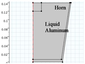
a)
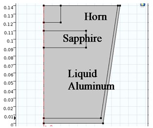
b)
3. Results and discussions
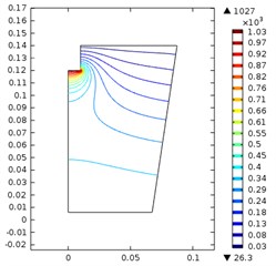
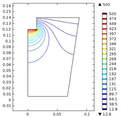
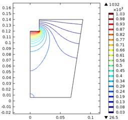
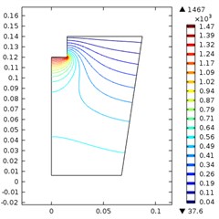
The effects of the ultrasonic horn and the input power is shown in the Fig. 2. The nine figures in the Fig. 2 corresponds to nine situations, i.e. the diameter of ultrasonic horn was 20, 30 and 40 mm and the input power was 200 w, 500 w and 800 w.
When the diameter was 20 mm, the maximum sound pressure increased from 326 kPa to 1.03 MPa as the power increased from 200 w to 800 w. The high vibration density area located near the horn.
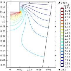
When the diameter was 30 mm, the maximum sound pressure increased from 500 kPa to 1.47 MPa as the power increased from 200 w to 800 w. The high vibration density area located near the horn. It is noticeable that, as the diameter of the horn increased, the same power was scattered on a larger area, and it may theoretically decrease the maximum pressure. However, the maximum pressure increased and the high-density area expanded and reached a deeper place.
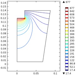
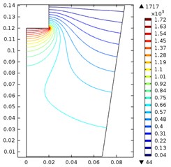
When the diameter was 40 mm, the maximum sound pressure increased from 677 kPa to 1.72 MPa as the power increased from 200 w to 800 w. The maximum pressure and high-density area expanded further comparing to situations. Thus, it is clear that the maximum sound pressure is not only decided by the ultrasonic power, but also decided by the size of the horn. This phenomenon is out of our expectation. The reason for this counterintuitive result may come from the coupling of the solid/liquid interface.
It is clear that when the power increased, both the maximum pressure and the high-density area increased significantly. Thus, a bigger horn with higher output power shall be more favorable in the ultrasonic treating.
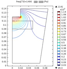
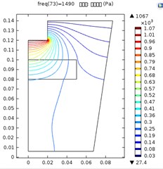
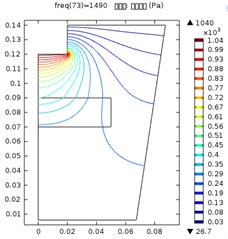
The effects of the distance between the ultrasonic horn and the sapphire plate is shown in the Fig. 3, where the ultrasonic horn diameter was 40 mm and the input power was 800 w.
Fig. 2Ultrasonic vibration when the ultrasonic horn diameter and input power were: a) 20 mm, 200 w, b) 20 mm, 500 w, c) 20 mm, 800 w, d) 30 mm, 200 w, e) 30 mm, 500 w, f) 30 mm, 800 w, g) 40 mm, 200 w, h) 40 mm, 500 w, i) 40 mm, 800 w
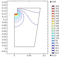
a)
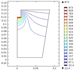
b)
c)
d)
e)
f)
g)
h)
i)
Fig. 3Ultrasonic vibration distribution when the distance between the ultrasonic horn and sapphire was: a) 10 mm; b) 20mm, c) 30 mm
a)
b)
c)
The maximum ultrasonic pressure when the distance between the horn and the sapphire plate was 10 mm, 20 mm and 30 mm was 1.14 kPa, 1.07 kPa and 1.04 kPa. Comparing to the result in Fig. 2(i), the maximum pressure decreased significantly in these three conditions. This may result from the existence of sapphire plate disturbed the normal distribution of vibration. Moreover, the further is the sapphire plate from the horn, the more significantly the maximum pressure was decreased. And lastly, the contour lines in the figures showed a significant curve at the sapphire/liquid interface, which indicates a significant energy absorption there. Contour lines with higher values was affected more significantly, while those with lower values were merely slightly changed. This indicated that high-energy vibration was absorbed more than low energy vibration at the interface.
In all the three conditions, vibration density in the sapphire plate center was higher than that on the edge. The further the sapphire was from the horn, the lower the maximum pressure and the pressure grads on the surface were. Therefore, it is reasonable to state that, for an ultrasonic treatment procedure, it is essential to select proper distance according to the aim. If a fast treatment on a selected area is desired, short distance between the sapphire and the horn shall be selected. Otherwise, if an even treatment on the whole surface is needed, the sapphire plate shall be placed further to the horn.
4. Conclusions
FEM is used to analyze the distribution of ultrasonic vibration in a sapphire treatment procedure, and the following conclusion can be drawn:
1) Shape of the ultrasonic horn significantly affects the ultrasonic vibration.
2) Existence of sapphire in the ultrasonic treatment bath can significantly reduce the vibration density on general.
3) The vibration energy can be significantly absorbed at the liquid/sapphire interface. And high-energy vibration can be absorbed more significantly.
4) Vibration energy grads can be formed on sapphire surface. And this phenomenon shall be used to achieve different aims.
References
-
Horng R. H. Thermal management and light extraction in multi-chip and high-voltage LEDs by cup-shaped copper heat spreader technology. Light-Emitting Diodes: Materials, Devices, and Applications for Solid State Lighting XVII, 2013, p. 86410R.
-
de Pablos-Martin A., Ebert M., Patzig C., Krause M., Dyrba M. Laser welding of sapphire wafers using a thin-film fresnoite glass solder. Microsystem Technologies-Micro and Nanosystems-Information Storage and Processing Systems, Vol. 21, 2015, p. 1035-1045.
-
Li Y., Liu S. Research on the soldering of sapphire optical filter used in infrared detector. Laser and Infrared, Vol. 44, 2014, p. 387-390.
-
Gorbaty Y. E., Bondarenko G. V., Mileiko S. T. Soldered high-pressure high-temperature sapphire window. Review of Scientific Instruments, Vol. 65, Issue 8, 1994, p. 2739-2740.
-
Ramirez A. G., Mavoori H., Jin S. H. Bonding nature of rare-earth-containing lead-free solders. Applied Physics Letters, Vol. 80, Issue 3, 2002, p. 398-400.
-
Mavoori H., Ramirez A. G., Jin S. H. Universal solders for direct and powerful bonding on semiconductors, diamond, and optical materials. Applied Physics Letters, Vol. 78, Issue 19, 2001, p. 2976-2978.
-
Cui W., Li S., Yan J., et al. Ultrasonic-assisted brazing of sapphire with high strength Al-4.5Cu-1.5Mg alloy. Ceramics International, Vol. 41, Issue 6, 2015, p. 8014-8022.
-
Cui W., Yan J., Dai Y., et al. Building a nano-crystalline alpha-alumina layer at a liquid metal/sapphire interface by ultrasound. Ultrasonics Sonochemistry, Vol. 22, Issue 1, 2015, p. 108-112.
About this article
This research is sponsored by the Natural Science Foundation of Jiangsu Province (Nos. BK20160285 and BK20170320) and National Natural Science Foundation of China (Grant No. 51605141 and 51705039).
