Abstract
A dynamic model of a galloping transmission line able to describe for the coupling of its longitudinal, in-plane, out-of-plane and torsional vibrations is established. It also considers the effects of geometrical nonlinearity and aerodynamic nonlinearity. By the static configuration, the reduced model is obtained. Then, the equations of motion are obtained through the Galerkin method. It contains two in-plane, two out-of-plane and two torsional components. By numerical calculation, the maximum amplitudes at wind speeds are drawn and the galloping behavior of transmission line with thin ice accretions is analyzed. The obtained results show that the second galloping mode is more triggered. The double-mode galloping occurs in all motions, in which the maximum amplitude is bigger than in single-mode galloping. And the double-mode galloping presents the track of inclined ‘8’ in longitudinal direction.
1. Introduction
Galloping of iced transmission lines is a self-excited vibration with low frequency and high amplitude, which is a serious problem in the safe operation of the entire power transmission system. Many efforts have been done to investigate the galloping. Den Hartog [1] established the vertical galloping model and proposed the vertical galloping mechanism. Luongo [2] and Jones [3] proposed the vertical-horizontal coupling model to account for the galloping behavior, which neglected the effect of torsion motion. Through a detailed aerodynamic wind tunnel study on iced transmission line, Nigol [4, 5] proposed that galloping was caused largely by the self-excited torsional mechanism. Yu. P [6] investigated the vertical-torsional coupling system and proposed inertially coupled galloping mechanism. Hence, through experimental and theoretical analysis, it was verified that the torsion motion played a significant role in galloping behavior of transmission line. Zhang et al. [7] also established the model with vertical-torsional motions and studied the influence of the system parameters on the amplitude of galloping. Lou et al. [8] proposed a model to describe three-dimensional galloping behavior and studied the bifurcation and stability behavior for nonlinear galloping of iced transmission lines. Huo et al. [9] proposed the model of a transmission line to describe for the coupling of its in-plane, out-of-plane and torsional vibrations. Then, by the singularity theory, they investigated the effects of the parameters on system.
Most of the above studies used the Galerkin method, which is usually adopted to disperse the partial different equations and reserves the concerned modes. However, through the study on suspended cable, we can find that the symmetric in-plane modes consist of antisymmetric vertical components and symmetric longitudinal components [10, 11]. Hence, the phenomenon of frequency crossover occurs, which causes the order exchange of symmetric and antisymmetric modes [12]. Based on this theory, Yu. P et al. [13] and Luongo et al. [14] adopted the galloping model of the coupling of in-plane, out-of-plane and torsional vibrations, in which the longitudinal motion was simplified, to study the internal resonance behavior of conductor galloping and the effect of twist on nonlinear galloping respectively. However, the nonlinear dynamic investigations were only focused on the first mode, which neglected the higher mode.
Hence, the objective of the present paper is to investigate the effect of the higher mode on galloping. The dynamic model of the transmission line containing the coupling effects of the longitudinal, in-plane, out-of-plane and torsional vibrations is established, which also considered the effects of geometrical nonlinearity and aerodynamic nonlinearity. Then, the first two-mode equations of motion are obtained through the Hamilton’s principle and the Galerkin method. By numerical calculation, the galloping behavior is analyzed at wind speeds and the effects of the coupling mode on galloping behavior are also investigated.
2. The dynamic model
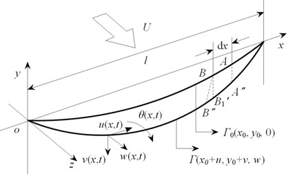
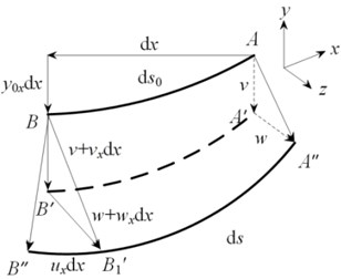
The transmission line is modeled as a body made of flexible cable with length l, in which the effect of the flexural rigidity is neglected due to a small sag-to-span ratio. A crescent-shaped thin ice accretion that is assumed to be uniform along the transmission line is considered. Both ends of the transmission line are considered to be fixed for the rigid body assumption of the tower [15]. The initial configuration of conductor, Γ0, which just goes by gravity of the conductor and the ice, and the dynamic configuration, Γ, are shown in Fig. 1(a). The symbols u(x,t), v(x,t), w(x,t), θ(x,t) denote the longitudinal, in-plane, out-of-plane and torsional dynamic displacements respectively at time t. An infinitesimal length of the transmission line, dx, is considered and its dynamic displacement is illustrated in Fig. 1(b).
Fig. 1The schematic diagram of transmission line model: a) configuration, b) dynamic displacement
a)
b)
Through the multivariate Taylor series expansion, the dynamic strain can be obtained:
where ds0 and ds mean the undeformed arc length and the deformed arc length respectively. The catenary equation, y0, is:
where H is the horizontal initial tension of the transmission line; m is the mass per unit length of the iced transmission line; g is gravitational acceleration.
The potential energy of the transmission line is given by:
where T0 is the initial tension of the transmission line, T0=H(1+y20x)1/2; EA and GJ are the in-plane and torsional stiffness. εθ is the torsional strain of the transmission line, εθ=∂θ/∂s0.
By the aerodynamic model of the iced transmission line and the effect of the thin ice accretions [16], the kinetic energy and the virtual work are given by:
where I is the mass moment of inertia per unit length at original point; Fu, Fv, Fw and M are the aerodynamic forces acting on the longitudinal, in-plane, out-of-plane and torsional direction of the iced conductor respectively. Their expressions are obtained by the reference [6], given by:
where Ur is relative wind velocity, Ur=√(U-˙w)2+˙v2+D˙θ/2; U and ρa are the mean wind speed and the air density; D is the diameter of a bare conductor; Cy,Cz, and CM are the aerodynamic coefficients; and ryi, rzi and rMi (i= 1, 2, 3) are the fitting coefficients obtained from the experimental data [17].
The equations of galloping are obtained through the Hamilton’s principle:
For a small θ, the equations of motion are found to be:
3. Galerkin discretization
By the static configuration [6, 11], a reduced model of the transmission line containing the in-plane, out-of-plane and torsional motions is derived from Eq. (7)-(10). Then, a discrete model is found by applying Galerkin procedure:
where qij(t)(i=v,w,θ,j=1,2) are the dynamic displacements for the in-plane, out-of-plane and torsional modes. φij(x) are the trial functions characterized by orthogonal series [10, 11]. Then, the discrete equations of the reduced model are given by:
where cij,ωg,ij(i=v,w,θ,j=1,2) are the damping ratios and natural frequencies respectively; gij,k are the integral constants; Fi1j1(˙qv1,˙qv2,˙qw1,˙qw2,qθ1,qθ2,˙qθ1,˙qθ2)(i1=v,w,j1=1,2) and Mθj1(˙qv1,˙qv2,˙qw1,˙qw2,qθ1,qθ2,˙qθ1,˙qθ2) are nonlinear aerodynamic terms of the in-plane and out-of-plane and torsional motions.
4. Numerical results and discussions
The numerical calculation of Eq. (12)-(17) is performed. The selected parameters are shown in Table 1 [17]. At the different wind speeds, the maximum amplitude curve of the first two modes is shown in Fig. 2. I-1st, O-1st and T-1st denote the first mode of the in-plane, out-of-plane and torsional galloping respectively. Meanwhile, I-2st, O-2st and T-2st denote the corresponding second modes.
From Fig. 2, we can see that the first two modes in three directions all show the limit-amplitude galloping. Taking the in-plane galloping as an example, with the increase of the wind speed, the first two modes are triggered successively. Meanwhile, the double-mode galloping area is found (3-8 m/s). In addition, under the selected parameters in Table 1, the maximum galloping amplitude of the second mode is bigger than that of the first mode. Similarly, the galloping area triggered in second mode (3 m/s-16 m/s) is wider than that in first mode (1-8 m/s).
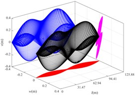
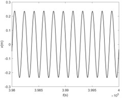
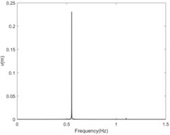
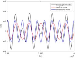
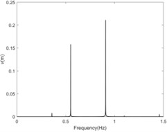
The double-mode galloping should be got more attention. Then, the spatial galloping profiles at 5 m/s are shown in Fig. 3 containing the projections in three directions. Duo to the coupling galloping, no fixed nodes or peaks are presented in the galloping profiles. Considering that the second mode is on the node at l/2 span, only the first mode is contained, which is shown in Fig. 3(b), (c). However, there are two modes at 3l/4 span, including the first mode (0.550 Hz) and the second mode (0.909 Hz), which is shown in Fig. 3(d), (e). Furthermore, from Fig. 3(d), we can see that the amplitudes present the superposition or counteract, the maximum of which is bigger than that in single-mode area. Hence, the antisymmetrical mode of vibration is presented. Meanwhile, the galloping track shows the inclined ‘8’ motion in double-mode area while it shows the elliptical motion in single-mode area along the longitudinal direction
Table 1Parameters of transmission line
Parameter | Data | Parameter | Data | Parameter | Data |
H (N) | 30000 | A (mm2) | 423.24 | ρa (kg/m3) | 1.29 |
l (m) | 125.88 | GJ (N m2/rad) | 101 | ξvj (j= 1,2) | 0.01, 0.012 |
m (kg/m) | 2.379 | I (kg/m) | 0.3344×10⁻³ | ξwj (j= 1,2) | 0.03, 0.036 |
E (N/m2) | 4.78×10¹⁰ | the initial angle of ice (θ0) | 40° | ξθj (j= 1,2) | 0.10, 0.12 |
Note: ξvj, ξwj and ξθj denote the damping ratios of in-plane, out-of-plane and torsional motions respectively | |||||
Fig. 2The maximum amplitude of the first two modes
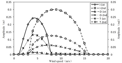
Fig. 3The double-mode galloping at 5 m/s: a) the spatial galloping profiles, b) the time history at l/2 span, c) the amplitude-frequency responses at l/2 span, d) the time history at 3l/4 span, e) the amplitude-frequency responses at 3l/4 span
a)
b)
c)
d)
e)
5. Conclusions
For the iced transmission line, the continuous elastic dynamic model is established, containing the longitudinal, in-plane, out-of-plane and torsional motions. Then, through the static configuration and Galerkin Discretization, the nonlinear equations of motions are obtained, which contain two in-plane, two out-of-plane and two torsional components. The galloping behavior is analyzed as follows:
1) The first two modes present the limit-amplitude galloping. As the wind speeds increases, the first mode, the coupling mode and the second mode will be appeared in turn.
2) The galloping area of the second mode triggered by the wind speed is wider than that of the first mode. And the maximum amplitude is even bigger in double-mode galloping area than in single-mode galloping area.
3) Once the coupling mode occurs, the galloping track presents the inclined ‘8’ motion along the longitudinal direction. However, it shows the elliptical motion in single-mode area.
References
-
Den Hartog J. P. Transmission line vibration due to sleet. Transactions of the American Institute of Electrical Engineers, Vol. 51, Issue 4, 1932, p. 1074-1076.
-
Jones K. F. Coupled vertical and horizontal galloping. Journal of Engineering Mechanics, Vol. 118, Issue 1, 1992, p. 92-107.
-
Luongo A., Piccardo G. Non-linear galloping of sagged cables in 1: 2 internal resonance. Journal of Sound and Vibration, Vol. 214, Issue 5, 1998, p. 915-940.
-
Nigol O., Buchan P. G. Conductor galloping part I-Den Hartog mechanism. IEEE Transactions on Power Apparatus and Systems, Vol. PAS-100, Issue 2, 1981, p. 699-707.
-
Nigol O., Buchan P. G. Conductor galloping-part II Torsional mechanism. IEEE Transactions on Power Apparatus and Systems, Vol. PAS-100, Issue 2, 1981, p. 708-720.
-
Yu P., Shah A. H., Popplewell N. Inertially Coupled Galloping of Iced Conductors. Journal of Applied Mechanics, Vol. 59, Issue 1, 1992, p. 140-145.
-
Zhang H., Li X., Zhang L., et al. Theoretical and numerical analysis of galloping of bundle conductors. Power and Energy Engineering Conference, 2011.
-
Lou W., Yang L., Huang M. F., et al. Two-parameter bifurcation and stability analysis for nonlinear galloping of iced transmission lines. Journal of Engineering Mechanics, Vol. 140, Issue 11, 2014, p. 04014081.
-
Huo B., Liu X. J., Zhang S. X., Liu P. Singularity and chaos of nonlinear galloping for an iced transmission line. Journal of Vibration and Shock, Vol. 34, Issue 13, 2015, p. 36-41+47.
-
Irvine H. M., Caughey T. K. The linear theory of free vibrations of a suspended cable. Proceedings of the Royal Society of London A, Vol. 341, Issue 1626, 1974, p. 299-315.
-
Nayfeh A. H., Arafat H. N., Chin C. M., et al. Multimode interactions in suspended cables. Modal Analysis, Vol. 8, Issue 3, 2002, p. 337-387.
-
Mansour A., Mekki O. B., Montassar S., et al. Catenary-induced geometric nonlinearity effects on cable linear vibrations. Journal of Sound and Vibration, Vol. 413, 2018, p. 332-353.
-
Yu P., Desai Y. M., Shah A. H., et al. Three-degree-of-freedom model for galloping. Part I: Formulation. Journal of Engineering Mechanics, Vol. 119, Issue 12, 1993, p. 2404-2425.
-
Luongo A., Zulli D., Piccardo G. On the effect of twist angle on nonlinear galloping of suspended cables. Computers and Structures, Vol. 87, Issues 15-16, 2009, p. 1003-1014.
-
Liu X., Huo B. Nonlinear vibration and multimodal interaction analysis of transmission line with thin ice accretions. International Journal of Applied Mechanics, Vol. 7, Issue 1, 2015, p. 1550007.
-
Mccomber P., Paradis A. A cable galloping model for thin ice accretions. Atmospheric Research, Vol. 46, Issues 1-2, 1998, p. 13-25.
-
Zhang Q., Popplewell N., Shah A. H. Galloping of bundle conductor. Journal of Sound and Vibration, Vol. 234, Issue 1, 2000, p. 115-134.
Cited by
About this article
The authors gratefully acknowledge the support of the National Natural Science Foundation of China (51479136 and 51808389), the Project of Tianjin Municipal Transportation Commission (2018B-33), the Project of Tianjin Natural Science Foundation (17JCYBJC18700 and 18JCQNJC08000).

