Abstract
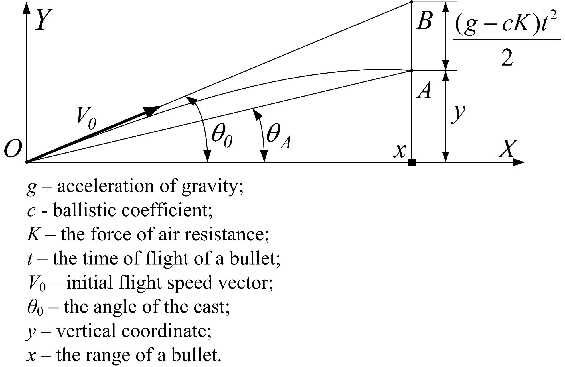
In the article, the flight trajectory of a material point in the atmosphere is considered. For its calculation the Runge-Kutta method and the system of the equations of external ballistics are used. Moreover, the approximation of the resistance function according to the 1943-year law for subsonic and supersonic speeds is made. The expansion of dependences of the excess above the line of aiming and flight time from the distance in Taylor’s series is implemented. The results of researches are used in solving the direct problem of external ballistics for the definition of trajectory parameters with an increased accuracy.
Highlights
- The models of the trajectory of a straight shot for the excess above the line of aiming and flight time have been developed
- The regressive equation for the function of air resistance 𝐺(𝑉), which error does not exceed 0,11 % in the speed range 540 ≤ 𝑉 ≤ 900 m/s has been found
- In the case of a flat trajectory it is possible to calculate the trajectory with the 1 mm error for supersonic speeds and the 2 mm error for subsonic speeds
- In the case of a flat trajectory it is possible to calculate the time at a given range with the error under minimum MSK by analytical formulas
- The results of researches are used in solving the direct problem of external ballistics for the definition of trajectory parameters with an increased accuracy
1. Introduction
In light targets and opto-electronic blocks for speed measurement and bullet deceleration (a form coefficient) an indirect measurement method is used. Initial measurable physical characteristics are time moments of the bullet flight through light screens (block planes). A measurement accuracy of time moments and accuracy of their binding to trajectory coordinates in the points of its meeting with the planes determine the accuracy of the computation of trajectory parameters. A measurement accuracy of time moments depends on the ratio of signal/noise, the steepness of the rising edge of the signal and the way of time moment registration (according to signal maximum, the middle of the time interval of the excess signal, the excess moment of the border level on the front and back signal line). Because of the inertness of opto-electronic transformers a back signal line is tightened more than a front one and the signal has unlimited duration theoretically. Therefore, it is worthwhile to use the fixation of time moment according to the excess method of border level signal by taking, obviously, an optimal time measurement, whose filter has maximum ratio of signal/noise [1].
The binding accuracy of time moments to trajectory coordinates partly connects with the measurement accuracy since block planes have finite thickness and it is difficult or practically impossible to set how deep a bullet is in this plane when a time meter has worked out. If the planes are identical, all the planes have the same spatial and, correspondingly, time shift and time intervals between the planes stay invariable. In other words, during the speed change or deceleration base offset happens but the base line stays unchangeable.
It is quite another matter when we talk about the spatial position of the planes because it is rather problematic to set a value exactly enough, so it is worthwhile to identify the time models and the meeting points of the trajectory and the plane.
2. System model
Now we will take the right coordinate system, accepted in external ballistics [2-5]. In the case of the target, it is more convenient to use the coordinate system of the target (Fig. 1), the plane YOZ is matching with the target plane, the axis OY is vertical, but the axis OX is horizontal and it is directed to the line of fire. The equation of the block plane P(a,b,r) is presented below [6-8]:
where: a=tgγ, b=-tgβ.
Next, we will take the trajectory of the close target as a line and set it in a parametric form (Fig. 2):
where l=cosα, m=cosβ, n=cosγ – the guide cosines of the trajectory, p – the parameter, representing the distance along the trajectory between points А(xM,yM,zM) and B(x,y,z), xM= 0.
The setting of the spatial position concerning the coordinate system X'Y'Z', connected with the position in the point O' (Fig. 3), formalizes by means of matrix transformations, used in CAD and robotics [9-11]. A parallel translation from the point О of the coordinate system XYZ in the point O' of the coordinate system X'Y'Z' is described like a matrix equation:
where T – the transportation index, PT(x',y',z') – the row vector of suitable coordinates.
Now we will mark through M(x,α), M(y,β), M(z,γ) the rotation matrixes about the axes X, y, Z respectively on the angles α, β, γ. In the right coordinate system at the turn anticlockwise we have:
where: c1=cosα, c2=cosβ, c3=cosγ, s1=sinα, s2=sinβ, s3=sinγ represent the guide cosines and sinus.
The transfer from the coordinate system XYZ to the coordinate system X3Y3Z3 (Fig. 3) is performed by the parallel translation to the point (xp, yp, zp) and the turn consistently about the axis Y' on the angle of the course ψ, about the axis Z1 on the angle of elevation ϑ* and about the axis X2 on the angle of dump φ. As a result, we get:
x0=x-xp,y0=y-yp,z0=z-zp,xp=-L.
The angles of the cast and the course are situated on the coordinates of two points of the line (Fig. 4) in the following way:
The guide cosines of the line with the angles of the cast and the course, corresponding Eq. (6), are equal:
In the close target on the blocked area of the length 4-6 m along the axis OX a trajectory turns into a line, a tangent trajectory in the point of impact in the target (the registration plane X'Y'Z' on Fig. 5).
Fig. 1Setting of the equation of the light plane
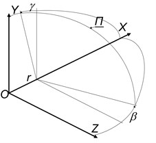
Fig. 2Setting of the line in a parametric form
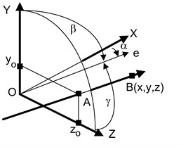
Fig. 3Spatial scheme of the coordinate transformation
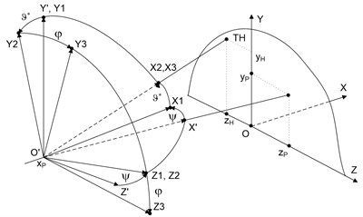
Fig. 4Scheme for the definition of the guide cosines
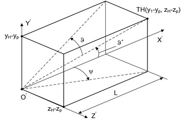
Fig. 5Firing corridor
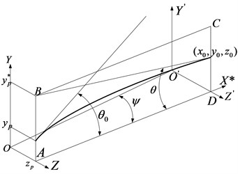
The point of intersection of this line and the position plane creates a conventional (fictitious) flight point with the coordinates y*p, zp.
For the calculation of the flight trajectory of a material point in the atmosphere according to the Runge-Kutta method [12] we will use the equations of external ballistics, recorded by arguments t, x and θ in Cartesian coordinate system XYZ (right three), the plane XY coincides with fire plane [2-5]. The axis OX is horizontal and coincides with fire line, the axis OY is vertical, and the beginning of coordinates coincides with the point of the bullet flight. The coordinate system by the argument t [3, 4] at a height y= 0:
The coordinate system by the argument x:
The coordinate system by the argument θ:
In Eqs. (8-13) u – velocity vector projection V on the axis OX; θ – angle of inclination of tangent to trajectory; F(V)=VG(V)=0,00048104V2cx(V/a), F(V), G(V), cx(V/a) – table functions of air consistency, c – ballistic coefficient of the bullet.
For caliber bullet 7,62 mm we have c= 6,9 m2/kg In the speed range 540 ≤ V ≤ 900 m/s resistance function under the law of 1943-year is approximated by regressive dependence:
In which connection the standard error of the approximation does not exceed 0,16 %. In the speed range 580 ≤ V ≤ 900 m/s resistance function is 0,0466002 + 0,00008144V, in which connection the standard error of the approximation does not exceed 0,11 % and is conditioned more by the presentation of function values using three decimal places.
3. Computational experiment
In the case of the flat trajectory, which the bullet trajectory is during the firing from the small arms by direct fire, we will take the decomposition of the functions y(x) and t(x) in Taylor’s series in the area of a starting point (a flight point):
For the series Eq. (15) with a cubic term inclusive, we will use famous ratios [4]:
and for the term from the x4 series Eq. (15) and all the five terms of the series Eq. (16) we will get ratios analogically, using the equations of higher ballistics Eq. (8-13).
We have:
From Eqs. (8) and (10):
We have:
where G'v(V) – partial derivative with respect to V.
Now:
Thus, a quartic polynomial, corresponding to the series Eq. (15), looks like:
In the case of the series Eq. (16) we find consistently:
From Eq. (27) taking into consideration Eqs. (28)-(30) and (13), (19) we have t4(x) and the expansion coefficients in the series:
Since in coefficients, beginning from a4 and b3, derivatives from the table function G(M) are included, we will limit a4 and b4. In the case of the approximation G(V) using the ratio derivatives Eq. (14), beginning from the second one, vanish, through this the expressions for subsequent coefficients simplify and if necessary they are easy to be calculated.
According to the Taylor’s range theory it will accurately represent the functions in the point, if the last one from accounted derivatives is calculated in some mid-point. If we take an arithmetical mean (for this segment) argument value, for example, then the accuracy with a limited number of terms of series increases and corresponds to the accuracy of the series with an additional term [4]. Without calculating the coefficient of an additional term, we will use the following technique. Since time t and the coordinate y at a given range can be determined by the numerical integration of the equations of external ballistics, for example, by the Runge-Kutta method, then we will add an additional term of the series, after that we will find its coefficient from the condition of given time or coordinate at a given range.
Though, for example, the coefficients of the series Eqs. (22) are known and we will add the following coefficient a5, that we have determined from the condition y(L)=yM, i.e. from the condition of the known (counted) coordinate yM at the distance of the target L. The coordinate yM can be determined as the point of impact in the target with the shot then:
If starting conditions γ0=tgθ0, v0 and ballistic coefficient c are unknown, we are able to try to approximate excess and time by polynomials in the presence of changes in some points of the trajectory. In this case, the coefficients of the polynomials will be devoid of physical meaning.
4. Conclusions
The models of the trajectory of a straight shot for the excess above the line of aiming and flight time with elaboration by additional terms of Taylor’s series have been developed, their coefficients are found from the condition of the passage of solution through a final point (at a given range) of the trajectory. The approximation of the trajectory for excess and time using polynomials can be accurate enough. At the same time, we can approximate not the whole trajectory but only the interesting segment for us, for example, in the area of placing of block planes and a light target.
The regressive equation for the function of air resistance G(V), which error does not exceed 0,11 % in the speed range 540 ≤ V ≤ 900 m/s has been found.
In the case of a flat trajectory it is possible to calculate the trajectory with the 1 mm error for supersonic speeds and the 2 mm error for subsonic speeds and also to calculate the time at a given range with the error under minimum MSK by analytical formulas without resorting to the integration of differential equations of external ballistics.
The results of researches are used in solving the direct problem of external ballistics for the definition of trajectory parameters with an increased accuracy.
References
-
Levin V. P. Theoretical Footings of Statistic Radiotechnics. Book 2, Sov. Radio, Moscow, 1968, p. 504.
-
Dmitrievskiy А. А. External ballistics. Mechanical Engineering, 1979, p. 479.
-
Ermolaev S. I. External Ballistics. VMACV named after А. М. Krylov, 1958, p. 688.
-
Konovalov А. А. External Ballistics. IPM UrО RAN, 2003, p. 191.
-
Shapiro Ya М. External Ballistics. Oborongiz, Moscow, 1951, p. 379.
-
Beklemishev D. V. Course of Analytical Geometry and Linear Algebra. Science, Moscow, 1974, p. 320.
-
Bronstein I. N. Handbook of Mathematics for Engineers and Students of Universities. Science, Leipzig, Toybner, 1981, p. 719.
-
Nicholas G. Reference ballistic chronograph. Optical Engineering, Vol. 48, Issue 4, 2009, p. 43602.
-
Mathematics and CAD, Book 1. Main Methods and the Theory of Poles. World, Moscow, 1988, p. 206.
-
Mathematics and CAD, Book 2. Computational Methods, Geometrical Methods. World, Moscow, 1988, p. 206.
-
Shahinpur М. Course of Robotics. World, Moscow, 1990, p. 527.
-
Bahvalov N. S. Numerical Methods. Science, Moscow, 1973, p 632.
-
Bahvalov N. S. Numerical Methods. Science, Moscow, 1987, p. 598.
-
Dennis E. Tschudi Ballistic Velocity Measurement System Having Dual Sensor Unit with Parabolic Slit Mirrors. United States Patent, US006020594A, 2000.
-
Li Hanshan, et al. The apply on photoelectric detection target and its development in exterior ballistic test system. Procedia Engineering, Vol. 15, 2011, p. 1451-1455.
-
Ryan Decker, et al. Measurement of bullet impact conditions using automated in-flight photography system. Defence Technology, Vol. 13, 2017, p. 288-294.
-
Postnikov М. М. Analytical Geometry. Science, Moscow, 1973, p. 752.

