Abstract
A new perturbation method has been proposed to investigate the sensitivities of the eigen-parameters (frequencies and mode shapes) and the modal strain energy density of a damaged beam. The sensitivities were obtained via the Rayleigh quotient and Taylor series expansion. The damage was simulated by the reduction in the cross-sectional area of the beam. The theoretical relationships were established between the damage parameter and the variations of the frequency and modal strain energy. The analytical formulae explicitly reveal the underlying mechanism that, the frequency, which is closely related to the modal strain energy of the entire structure, is less sensitive to the local damage; the modal strain energy density, on the other hand, is able to reflect the local damage in a small region. The results of the perturbation analyses were validated with the finite element analyses and experimental tests of the beam models with 2 damage levels. The first resonant frequencies decrease slightly with the increases of the damage. When 30 % of the cross-sectional area is cut off in the damaged zone, the first resonant frequencies are still 95 % and 98 % those of the intact beam for the bending vibration around x-axis and around y-axis; meanwhile, the modal strain energy increases 94 % and 54 % in the damage zone, which closely correlates with the local damage parameters. The proposed perturbation method has the potential to assess the quality of damage indictors faster and more easily than FE and experimental methods.
1. Introduction
Early detection and quantification of structural damages are of great importance to ensure the lifetime safety, prevent catastrophic events, and increase the service of structures. Currently available damage detection methods include magnetic field methods, ultrasonic methods, eddy-current methods, and thermal field methods [1], which are localized experimental methods. Most of these experimental methods require that the damage location is approximately known in advance and accessible for inspection. Due to these limitations, the need for global damage detection methods has led to the development of the static damage detection technology [2, 3] and dynamic damage detection technology [4]. The underlying idea behind the vibration-based technology is that, the changes in the physical properties (stiffness, mass, and damping) of a structure will cause detectable changes in its modal parameters (frequencies, modes, and strain energy) which are the functions of its physical properties [5, 6]. Hence, the changes in the modal parameters can be assumed as indictors for damage detection. The variations of the physical properties of a structure, caused by damages, include the reduction in the structural stiffness and modification of the structural geometry, etc. Vibration-based damage detection techniques have attracted much attention in past decades and many approaches have been developed, based on the vibration response of structures [7]. Early studies found that the resonant frequencies were less sensitive to low levels of damage [1, 8]. The frequencies, as global parameters, generally cannot provide spatial information about structural changes [1]. On the other hand, it has been experimentally proved that the mode shapes [7-9] and modal strain energy [10-13] are more sensitive to structural damages.
The damage detection methods using mode shapes and their derivatives as a basic feature are more sensitive to local damage as the mode shapes contain local information [7-9]. The traditional mode shape change method uses the mode shape changes between the intact and damaged structures as a basic feature for damage identification. The displacement mode shape itself is not very sensitive to a small damage. To enhance the sensitivity of mode shape data to the damage, the mode shape curvature has been proposed as a promising feature for damage identification [7, 8]. For beam-type or plate-type structures, the second derivatives of the mode shapes are highly sensitive to a damage and can be used to localize it [9]. The difference of the curvature mode shapes between the intact and damaged structures is introduced as a damage indicator [7]. The modal strain energy is directly related to the mode shape curvatures for beam-type or plate-type structures; as a special case of the mode shape curvature-based method, the modal strain energy has been widely used for damage identification [10-16]. A damage indictor was created [13, 17] based on the change in the modal strain energy between the intact and damaged structures. The selection of a damage indictor will affect the final results and accuracy of structural damage detection [4]. The effectiveness of a damage detection method is determined by its sensitivity to a structural damage.
The sensitivity of the modal strain energy-based methods is related to those of the eigen-pairs of the concerned system. A variety of methods for computing the derivatives of eigen-pairs have been developed by many researchers. When a damage occurs in a structure, it can be represented by a small perturbation of the original system [18, 19]. The variation of an eigen-function can be expressed as a linear combination of the eigen-functions of the undamaged structure [18-20]. This method employs the modal superposition idea and needs all the mode shapes to obtain an accurate sensitivity of each mode shape, which is almost an impossible task. Often only the lower order frequencies and associated mode shapes are calculated. Recently, the calculation of the derivative of an eigenvector was substantially simplified, it required only the information of the corresponding eigenvector to be differentiated [21]. Most of sensitivity analyses were based on the matrix theory of a discrete system. In matrix analyses, it is not easy to reveal the mechanism how the damage parameter influences the sensitivity of damage indictors [19], and the influential relationship are submerged by the matrix calculations. To the knowledge of the authors, there are not theoretical comparisons between the sensitivities of various damage detection methods based on a continuum model.
To introduce a damage indictor for structural damage detection, one essential issue is to effectively evaluate its sensitivity to the variation of the structural parameters. This paper aims to propose a perturbation method based on the Rayleigh quotient via a beam model to evaluate the sensitivities of the first frequency and the modal strain energy in a region. The perturbation of the eigen-function of the damaged beam is expressed as the Taylor series of the eigen-functions of the undamaged beam, and the sensitivities are obtained. The analytical relationships are established between the variation rates of the frequency and strain energy with the damage parameter. These relationships approximately illustrate the sensitivity of these damage indictors to a structural damage. The sensitivities of the frequency-based and modal strain energy-based methods are investigated and compared. Furthermore, the finite element (FE) simulations and experimental modal analyses are conducted to validate the results obtained in the perturbation analyses. It is expected that the proposed method would be able to approximately assess the quality of a damage indictor.
2. Method
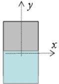
Consider the bending vibration of an elastic beam (Fig. 1). The Young’s modulus and mass density of the beam are denoted by E and ρ; the area and second moment of a cross section are denoted by A and I. A damage zone with a length of d exists at z=s. Assume that the length (L) of the beam is more than 10 times the characteristic length of its cross section, and it can be analyzed by the Euler beam theory [22].
2.1. Perturbation analysis of a beam
For the bending in a principal plane, the governing equation of free vibration of the beam is expressed in the variational form [23] as:
where Π=∫L0EIw''2dz is (2 times) the strain energy and Ψ=∫L0ρAw2dz is (2 times) the amplitude of kinetic energy, and where λ=ω2 is the eigen-value with ω being the (angular) frequency. Define Πij=∫L0EI⋅w''i⋅w''jdz and Ψij=∫L0ρA⋅wi⋅wjdz, where, λi, λj and wi, wj are the ith and jth eigen-values and eigen-functions of the undamaged beam, which satisfy the orthogonal conditions:
where δij is the Kronecker delta. It should be noted that Πij and Ψij are not tensors and a repeated index does not represent summation. The ith eigen-value λi satisfies the Rayleigh quotient:
Fig. 1Bending vibration of an elastic beam: a) location of a damage zone at the position z=s and the damage length is d, b) cut depth in the damage section

a)
b)
After a damage is introduced into the original intact beam, its EI and ρA have perturbations of Δ(EI)and Δ(ρA) respectively; hence, for the damaged beam:
The governing equation of the damaged beam in the variational form is:
with ˜Π=∫L0˜E˜I˜w''2dz and ˜Ψ=∫L0˜ρ˜A˜w2dz. Similarly, we define the integrations:
where, ˜wi and ˜wj are the ith and jth eigen-functions of the damaged beam, and the corresponding eigen-values are ˜λi and ˜λj. They satisfy the orthogonal conditions:
It is assumed that the eigen-pair, ˜λi and ˜wi, of the damaged beam are close to those of the undamaged beam, λi and wi; hence they can be expressed as:
where and are the perturbations of and , introduced by the damage.
By using Eqs. (4) and (8) and ignoring the terms higher than second order, Eq. (6) becomes:
and:
and then:
Following [24] and [18], the perturbation of the th eigen-function of the damaged beam can be expressed as the Taylor series of the eigen-functions of the undamaged beam:
where is the coefficient of the th eigen-function . Substituting Eq. (12) into Eqs. (9) and (11) and utilizing the orthogonal conditions Eq. (2), we have:
and:
Substitution of Eqs. (13) and (14) into the second equality of Eq. (7) yields:
For , Eq. (15) gives:
By using Eqs. (3) and (16), the sensitivity of the th eigen-value is:
For , Eq. (15) gives:
The quantity is found from Eq. (10) and the orthogonal conditions Eqs. (3) and (7), which leads to:
The modal strain energy stored in a region (say, the th) of the th mode is expressed as [19, 25, 26]:
where [] are the nodal coordinates of the th region. The change of the modal strain energy (by ignoring the terms higher than second order) is:
Substitution of Eq. (12) into Eq. (21) yields:
The beam model (Fig. 1) has a length 0.80 m and a rectangular cross section with a width 0.03 m and a height 0.06 m. The Young’s modulus, Poisson’s ratio, and mass density of the beam (steel) are 210 GPa, 0.3, and 7800 kg/m3. Two damage levels (10 % and 30 %) are introduced into the damage zone ( 0.02 m), i.e., the portion of is removed (here 10 % and 30 % respectively) along the bottom of the damage zone (Fig. 2).
Table 1Reduction ratios of the area and its second moment induced by a cut in a cross section
/ | / | / | / | ||||
0.9 | 0.9 | 0.729 | 0.9 | 0.1 | –0.1 | –0.271 | –0.1 |
0.7 | 0.7 | 0.343 | 0.7 | 0.3 | –0.3 | –0.657 | –0.3 |
As the damage is localized in a small zone where the cross sectional area, , of the beam and its second moment, , are reduced; thus, and in the damage zone, everywhere else 0 and 0. The reduction ratios of the cross sectional area and flexible rigidity (and ) are related to the parameter as listed in Table 1. As the second moment of a cross section area is different about and -axis, the reduction ratio of the second moment is denoted by and for bending around and -axis respectively. In the table, and are the height and area of the cross section in the damage zone and and are the corresponding second moment of the cross section about and -axis; and are the second moment of the cross section about and -axis. It is easy to obtain that: , , and .
For the beam concerned, Eq. (16) gives:
From Eq. (17), the sensitivity of the th eigen-value is simplified to:
Eqs. (18) and (19) give:
and:
For the case that the th region falls within the damage zone [], i.e., , from Eqs. (22) and (20), the change rate of the modal strain energy for the th mode can be expressed as:
If the region concerned is outside the damage zone, 0, then Eqs. (22) and (20) lead to:
The beam is divided into 80 regions, and the modal strain energy for the first modes and its change rates are calculated for the two damage levels. The integrations are carried out in a MATLAB program. The eigen-pairs of an intact beam under free-free boundary conditions are listed in the Appendix.
2.2. FE analyses
For the sake of validations, the FE analyses of the steel beam (Fig. 2) are conducted. Besides the intact beam model, 2 damage levels (10 % and 30 %) are considered in the damage zone ( 0.02 m). The software package ABAQUS (SIMULIA Inc., Providence, USA) is used to obtain the first 8 resonant frequencies, mode shapes, and the corresponding strain energy density in each element. Both ends are set free, and about 12400 continuum elements (C3D8R) are used.
Fig. 2FE mesh of the steel beam

2.3. Experimental modal analyses
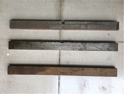
The experimental set-up (Fig. 3) for modal analysis includes an excitation hammer, response measuring sensors (accelerometers) and an acquisition system (JM3840, Jing-Ming Technology Inc., Yangzhou, China). The specimen is laid on sponge (Fig. 3) to simulate free-free boundary condition. Totally 10 accelerometers with nominal sensitivity of 100 mV/g are attached on the top surface of the beam. The impulse force is provided by the micro-hammer instrumented with a force sensor to measure the input force. The time histories of the force and acceleration are collected by the acquisition instrument and analyzed in a computer. The frequency response functions (FRFs) and the modal parameters are gained by using the kit software associated with JM3840 acquisition instrument. The parameters of the experimental instruments are listed in Table 2.
Fig. 3Experimental set-up for modal analyses and testing specimens

a)
b)
Table 2Parameters of the experimental instruments
Name | Pattern | Specifications | Manufacturer |
Excitation hammer/sensor | JML-03 | Sensibility: 0.08 mv/N | Jing-Ming Technology Inc., Yangzhou, China |
Accelerometer | YD2150 | Sensibility: 4.99 mv/m/s2 | Xi-Yuan Technology Inc., Yangzhou, China |
Data acquisition system | JM3840 | 16 channels; sampling rate: 2 kHz | Jing-Ming Technology Inc., Yangzhou, China |
Modal analysis software | JMTEST | Version 7.9 | Jing-Ming Technology Inc., Yangzhou, China |
Calculation of the strain energy in a region involves the displacement and rotation at the measurement points. As the rotation cannot be measured directly, it is usually estimated from the difference of the displacement values of two adjacent points [27], which may introduce substantial inaccuracy. Hence the strain energy density is not included into the experimental analyses in this paper.
3. Results and discussions
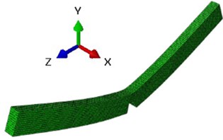
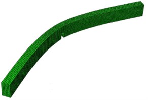
There are 2 vibration modes, i.e., bending around -axis and -axis. Fig, 4 shows the first mode shapes for the bending vibration around -axis and -axis.
The first resonant frequencies for bending vibration around -axis and -axis are obtained by using the 3 methods (perturbation, FE, and experimental) for 2 damage levels (Table 3). The first resonant frequencies decrease as the damage increases. The variation rates of the first resonant frequencies of the damaged beam from those of the intact beam are listed in the parentheses.
When the beam is cut off 10 % in the height in the damage zone, the bending stiffness is reduced 27 % around -axis and 10 % around -axis; which results in the frequency being reduced 2 % and 1 % respectively for the bending vibration around -axis and -axis. When the beam is cut off 30 % in the height, the bending stiffness is reduced 66 % around -axis and 30 % around -axis; which results in the frequency being reduced 5 % and 2 % respectively for the bending vibration around -axis and -axis.
Fig. 4The first mode shapes for bending vibration around x-axis and y-axis
a) First bending vibration mode around -axis
b) a) First bending vibration mode around -axis
Table 3Resonant frequencies and their variations obtained by 3 methods
– | Damage level | 0 % (intact) | 10 % | 30 % |
First bending mode around -axis | Perturbation | 487.97 (0 %) | 477.72 (–2.1 %) | 463.57 (–5.0 %) |
FE | 486.96 (0 %) | 477.23 (–2.0 %) | 430.39 (–11.6 %) | |
Experimental | 479.49 (0 %) | 471.19 (–1.7 %) | 424.81 (–11.4 %) | |
First bending mode around -axis | Perturbation | 243.98 (0 %) | 242.03 (–0.8 %) | 238.36 (–2.3 %) |
FE | 244.53 (0 %) | 243.36 (–0.5 %) | 237.82 (–2.7 %) | |
Experimental | 244.63 (0 %) | 242.68 (–0.8 %) | 238.77 (–2.4 %) |
The 3 methods obtain the similar variations of the first resonant frequencies. For the bending vibration around -axis, the perturbation method predicts 2 % and 5 % reduction in the first resonant frequency for the damage of 10 %, and 30% respectively; while the FE method predicts 2 % and 12 % reduction and the experimental method predicts 2 % and 11 % reduction. For the bending vibration around y-axis, the perturbation method predicts 1 % and 2 % reduction in the first resonant frequencies for the damage of 10 % and 30 % respectively; while the FE method predicts 1 % and 3 % reduction and the experimental method predicts 1 % and 2 % reduction.
The low sensitivity of the first eigenvalue to a damage of a structure has been demonstrated analytically by the beam model. As shown in Eq. (24), the denominator, , actually represents the strain energy of the whole beam for the first mode; while the integrals, and , represent the strain energy and kinetic energy stored at the damaged part for the first mode. The sensitivity of the first eigenvalue to the damage is proportional to the energy changes at the damage region and inversely related to the strain energy of the whole beam. As the damage region, [], is much smaller than the beam length, so the strain energy stored in the damage zone usually is much smaller than the strain energy of the whole beam. Furthermore, the coefficients is the same order as , both are smaller than 1. This explains why the change rate of the first eigen-value, , is less sensitive to the changes of the stiffness and mass in the damage zone. Additionally, the resonant frequency is less sensitive than the corresponding eigenvalue to the damage. The change of the first eigenvalue of the damaged beam is , and the change of the corresponding (angular) frequency is =. By using Taylor expansion for a small variation , its first-order approximation is (1+0.5). This result demonstrates that the change rate of the first frequency is only half that of the corresponding eigenvalue.
The perturbation method is able to predict relatively accurate results for the frequency variations for a small damage (see Table 3). For the case with 10 % damage, the three methods (perturbation, FE, and experimental) obtained similar results (–2.1 %, –2.0 %, and –1.7 %) for bending around -axis and (–0.8 %, –0.5 %, and –0.8 %) for bending around y-axis. For the case with 30 % damage, the three methods still produced similar results (–2.3 %, –2.7 %, and –2.4 %) for bending around -axis; however, for bending around -axis there existed evident difference (–5.0 %, –11.6 %, and –11.4 %) among the results predicted by the three methods. Firstly, for the sake of simplicity, the perturbation analyses only consider the first order increment, so it is more suitable for a small perturbation. As shown in Table 1, the reduction in the flexible rigidity (for bending around -axis) is more than 87 % for the case with 30 % damage, thus the perturbation analyses would have evident inaccuracy for this case (Table 3). Secondly, the damage is not symmetric about the neutral axis of the original beam and the stress distribution would be very complex in the damage location, hence the assumption of plane section in the Euler beam theory is not really suitable in the damage region, which will also induce the inaccuracy in this part.
Fig. 5Variation rate of strain energy density within elements: a) perturbation, b) FE

a) First mode of the bending vibration around -axis

b) First mode of the bending vibration around -axis
The change rates of the strain energy density stored in each region (compared with the value of the intact beam) are shown in Fig. 5 for the 2 methods (perturbation and FE) and the 2 damage levels. Both the perturbation and FE methods obtain the similar pattern of the change rates. The strain energy density varies dramatically in the damage zone and less obviously somewhere else. For the bending vibration around -axis, the perturbation method predicts 27 % and 65 % increase in the damaged part for the damage levels of 10 % and 30 % respectively; while the FE method predicts 18 % and 75 % increase in the damaged part. For the bending vibration around -axis, the perturbation method predicts 10 % and 28 % increase in the damaged part for the damage levels of 10 % and 30 % respectively; while the FE method predicts 20 % and 145 % increase in the damaged part.
The variation of the strain energy density indeed reflects the damage degree of the beam (Fig. 5). For the regions outside the damage zone, the change rate of the strain energy density is very small, as the coefficients are very small; for the regions within the damage zone, the change rate of the strain energy density is evident, as the coefficients is the same order as . For the bending vibration around -axis, the change rate of the modal strain energy density, which is mostly influenced by (i.e., ), can be as high as 27 % and 65 % respectively for the 2 damage levels; for the bending vibration around -axis, the change rate of the modal strain energy is 10 % and 28 % respectively for the 2 damage levels. These conclusions are also confirmed by the FE results (Table 3), both show same trend.
4. Conclusions
A perturbation method has been proposed for prediction of the changes in the resonant frequencies and modal strain energy due to a small damage of a structure. The sensitivities of the frequency and modal strain energy are expressed explicitly in analytical formulae. These formulations provides us with a clearer view of the mathematical framework to explain why the lowest resonant frequency, as a global mechanical parameter, is less sensitive to a local defect in a structure and why the modal strain energy density is more sensitive to a damage.
The proposed perturbation method is able to assess the quality of a damage indictor. It can be implemented more easily and faster than FE and experimental methods. The perturbation analyses have revealed that the change rate of the first resonant frequency is related to the energy change in the damage zone and inversely related to the strain energy of the whole beam; thus, it is less sensitive to damage in a small region. While the change rate of the strain energy density is closely related to damage in a small region; hence, it is more sensitive to a damage than the first resonant frequency. The conclusions obtained from the perturbation analyses are validated with the FE simulations of the damaged beam.
References
-
Cornwell P., Doebling S. W., Farrar C. R. Application of the strain energy damage detection method to plate-like structures. Journal of Sound and Vibration, Vol. 224, Issue 2, 1990, p. 359-374.
-
Courant R., Hilbert D. Methods of Mathematical Physics. Wiley, 1953.
-
Dessi D., Camerlengo G. Damage identification techniques via modal curvature analysis: overview and comparison. Mechanical Systems and Signal Processing, Vol. 52, 2015, p. 181-205.
-
Doebling S. W., Farrar C. R., Prime M. B. A summary review of vibration-based damage identification methods. Shock and Vibration Digest, Vol. 30, Issue 2, 1998, p. 91-105.
-
Doebling S. W., Hemez F. M., Peterson L. D., Farhat C. Improved damage location accuracy using strain energy-based mode selection criteria. AIAA Journal, Vol. 35, Issue 4, 2015, p. 693-699.
-
Entezami A., Shariatmadar H. Damage detection in structural systems by improved sensitivity of modal strain energy and Tikhonov regularization method. International Journal of Dynamics and Control, Vol. 2, Issue 4, 2014, p. 509-520.
-
Fan W., Qiao P. Vibration-based damage identification methods: a review and comparative study. Structural Health Monitoring, Vol. 10, Issue 1, 2011, p. 83-111.
-
Fan W., Qiao P. A strain energy-based damage severity correction factor method for damage identification in plate-type structures. Mechanical Systems and Signal Processing, Vol. 28, 2012, p. 660-678.
-
Farrar C. R., Jauregui D. A. Comparative study of damage identification algorithms applied to a bridge: I. Experiment. Smart Materials and Structures, Vol. 7, Issue 5, 1998, p. 704-719.
-
Fox R. L., Kapoor M. P. Rates of change of eigenvalues and eigenvectors. AIAA Journal, Vol. 6, Issue 12, 1968, p. 2426-2429.
-
Guan H., Karbhari V. M. Improved damage detection method based on element modal strain damage index using sparse measurement. Journal of Sound and Vibration, Vol. 309, Issue 3, 2008, p. 465-494.
-
Hu H., Wu C. Development of scanning damage index for the damage detection of plate structures using modal strain energy method. Mechanical Systems and Signal Processing, Vol. 23, Issue 2, 2009, p. 274-287.
-
Kim J. T., Stubbs N. Improved damage identification method based on modal information. Journal of Sound and Vibration, Vol. 252, Issue 2, 2002, p. 223-238.
-
Li L., Hu Y., Wang X. Numerical methods for evaluating the sensitivity of element modal strain energy. Finite Elements in Analysis and Design, Vol. 64, 2013, p. 13-23.
-
Pandey A. K., Biswas M., Samman M. M. Damage detection from changes in curvature mode shapes. Journal of Sounds and Vibration, Vol. 145, Issue 2, 1991, p. 321-332.
-
Rao S. S. Vibration of Continuous Systems. Hoboken, N.J., Wiley, 2007.
-
Shi Z., Law S., Zhang L. Improved damage quantification from elemental modal strain energy change. Journal of Engineering Mechanics, Vol. 128, Issue 5, 2002, p. 521-529.
-
Stubbs N., Kim J. T. Damage localization in structures without baseline modal parameters. AIAA Journal, Vol. 34, Issue 8, 1996, p. 1644-1649.
-
Timoshenko S., Young D. H., Weaver W. Vibration Problems in Engineering. Wiley, New York, 1974.
-
Washizu K. Variational Methods in Elasticity and Plasticity. Pergamon Press, Oxford, New York, 1982.
-
Wu S., Zhou J., Rui S., Fei Q. Reformulation of elemental modal strain energy method based on strain modes for structural damage detection. Advances in Structural Engineering, Vol. 20, Issue 6, 2016, p. 896-905.
-
Yan Y., Cheng L., Wu Z., Yam L. Development in vibration-based structural damage detection technique. Mechanical Systems and Signal Processing, Vol. 21, Issue 5, 2007, p. 2198-2211.
-
Yazdanpanah O., Seyedpoor S. M., Bengar H. A. A new damage detection indicator for beams based on mode shape data. Structural Engineering and Mechanics, Vol. 53, Issue 4, 2015, p. 725-744.
About this article
This research was partially supported by the project (No. 31470908) of the National Natural Science Foundation of China.

