Abstract
This paper presents the effect of pad with transverse grooves on the axial vibration for a small thrust bearing under water lubricated. Due to downsizing of electronic devices, the component part such as the thrust bearing in the micro fabrication becomes small size. Therefore, to study the characteristic of vibration for a small thrust bearing under water lubricated is significant for high precision machining. The hydrodynamic lubrication model was used to predict the water film thickness, the water pressure profile, and the bearing stiffness. A finite difference method (FDM) and a Newton-Raphson scheme are employed to achieve numerical results, i.e. the water pressure distributions, the water lubricating film thicknesses and the bearing stiffness under the variation of groove depths. The grooved shape of pads, that examined in this paper, was elliptical shape. The equation of motion under the impulse excitation considering in the axial vibration for a small thrust bearing was solved by using a Runge-Kutta method. The numerical results showed that the use of elliptical transverse grooves is effective to increases the fluid film stiffness and the maximum displacement in the axial vibration is able to be reduced.
1. Introduction
The thrust bearing is a common machine element that widely used to support axial loads. For example, the thrust bearing for micro fabrication is used to manufacture electronic components. Now a day, downsizing of electronic devices such as digital cameras and smart-phones has been strongly demanded [1]. In order to produce the small parts in the electronic devices, the high-speed milling becomes important method to achieve high efficiency parts. However, an efficiency high-speed milling is affected by the vibration of small thrust bearing. Therefore, to study the vibration of small thrust bearing under water-lubricated is important for high precision machining. The previous papers work on the thrust bearing can be summary as follows. The axial oil film stiffness of tilting pad thrust bearing was investigated [2]. The grid sizes were studied numerically and the air pressure profile in a thrust bearing was presented in [3]. The large tilting pad thrust bearing under oil lubricant was considered. The angular stiffness coefficient was studied as presented in [4]. The hydrodynamic lubrication model was applied to analyze the characteristics of thrust bearing in a ship propulsion system. The pressure distribution and the minimum oil film thickness under varying loads and pad slops were numerically presented [5]. The effect of multiple orifices in bearing surface on the characteristic of air thrust bearing was presented in [6]. The air thrust bearings of hard disk drives (HDDs) considering spriral grooved bearing were numerically investigated [7-8]. However, it is obvious that the previous works mentioned above have not numerically investigated the effect of elliptical grooved surface on the axial vibration of small thrust bearing. This paper considered the stiffness of water film bearing under the variation of grooved depths. The axial vibration due to the impulse load for a thrust bearing under the variation of groove depths was also investigated numerically. In this paper, the thermal effect and the frictional torque have not been considered.
2. Governing equations
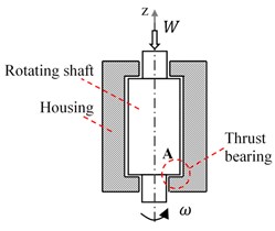
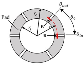
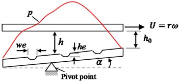
The governing equations used in the numerical procedure to analyze the characteristic of water lubricated small thrust bearing is presented. The schematic diagram of the small thrust bearing used in this paper is shown in Fig. 1. The shaft is rotating with ω rad/s. The water lubricant is contained between the housing and shaft surfaces. The thrust bearing with six pads is mounted at the A position as shown in Fig. 1(a) and the configuration of pad size is presented in Fig. 1(b). The water lubricating between the runner surface and the grooved pad surface under sliding condition forms the pressure distribution to support the axial load. In this paper, three grooves on a pad as shown in Fig. 1(c) is considered and the governing equations can be expressed as follows.
Fig. 1Schematic diagram of a small thrust bearing: a) a rotating shaft and a thrust bearing, b) pads for detail A, c) 3 grooves on one pad for the section view B-B
a)
b)
c)
The Reynolds equation for a polar coordinate is used to predicts the pressure profile between a runner surface and a pad surface is expressed as:
where p is the water pressure, μ is the water viscosity and h is the water film thickness that includes the groove parameters and the geometry of pad. The film thickness is able to estimated as shown in Eq. (2):
where δ(θ) is the shape of transverse groove locating on a pad and depending on the groove width (we), the groove depth (he), and the angular coordinate (θ). The load-carrying capacity W for N pads is obtained by the following integration:
The stiffness of water lubricant is calculated using Eq. (4) [6]:
The damping coefficient for an axial direction is assumed to be the piston-cylinder dashpot and can be estimated as [9]:
where d is the clearance of a rotating shaft and a housing, D is the shaft diameter, and L is a shaft length being in a housing. The dynamic response of the bearing to an impulse excitation is simplified as one degree of freedom. Therefore, the equation of motion for the bearing mass m in an axial direction z can be expressed as:
where fz(t) is a force acting on the system due to the impulse excitation.
3. Numerical procedure
For numerical analysis, the Eqs. (1), (2), and (3) must be converted into the dimensionless forms by using the following substitution:
The derivatives in the dimensionless Reynolds equation can be approximated by the finite difference method. The dimensionless pressure is obtained by using the Newton-Raphson iteration method. By substituting Eqs. (4) and (5) into the Eq. (6) and using the Runge-Kutta method, the dynamics response of a bearing for z direction can be obtained.
4. Numerical results and discussion
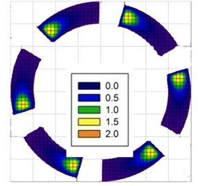
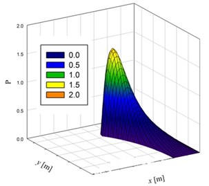
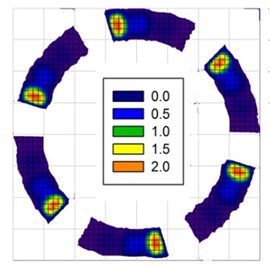
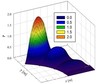
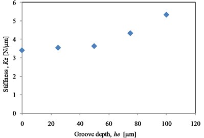
The numerical results in this paper were calculated with the following parameters: pads with the inner radius ri= 0.006 m, the outer radius ro= 0.008 m, the pad angle θ0=π/4 rad, the groove width we= 0.8 mm, the pivot angle α= 0.0182 rad and the number of pads N= 6. The shaft length L is 0.1 m, the shaft diameter D is 0.01595 m, the bearing mass m is 100 g and the clearance of a rotating shaft and a housing d is 25 µm. The numerical results of bearing characteristic such as the water pressure profiles, the minimum water film thickness and the fluid film stiffness are shown in Figs. 2, 3 and 4 respectively. The results show that the pressure profile is decreased at the inlet of grooved position then the pressure profile is increased rapidly at the exit of grooved position. Especially in the groove at the tail of pad, the pressure is clearly increased and higher than in the case of smooth pad as presented in Fig. 2. Due to the pressure drop in the inlet of grooved position, the water film thickness at the tail of pad will be decreased in order to form the pressure compensated for supporting the axial load. Therefore, the minimum water film thickness h0 is able to be decreased when increasing the groove depth as presented in Fig. 3. The fluid film bearing stiffness under varying groove depths as shown in Fig. 4 were calculated using the relative of the minimum film thickness and the load capacity. The results show that the groove depths of pad he are 0-50 µm, the stiffness increases slightly but the stiffness increases immediately when the groove depths of pad he are 75-100 µm.
Fig. 2Dimensionless pressure profiles in small thrust bearings: a) six smooth pads, b) one smooth pad, c) six pads with groove depth, he= 25 µm, d) one pad with groove depth, he= 25 µm
a)
b)
c)
d)
Fig. 3Effect of groove depth on the water film thickness in thrust bearing under ω= 10.000 rad/s
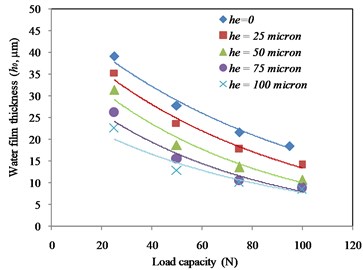
Fig. 4Bearing stiffness under varying groove depths (ω= 10.000 rad/s)
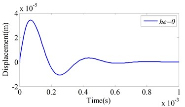
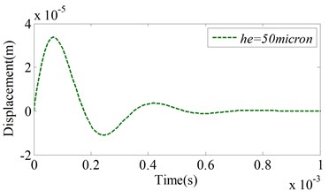
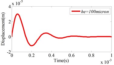
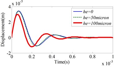
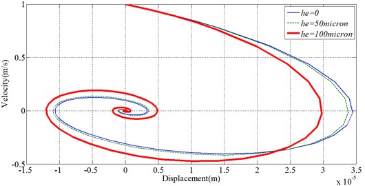
The axial displacement responses under the impulse excitation 100 N.ms and the rotational speed ω= 10.000 rad/s are presented in Figs. 5 and 6. The results show the comparisons of displacement for the smooth pad, the grooved pad with 50 µm depth, and the grooved pad with 100 µm depth. All the case studies show that the responses of the system decay very fast with time period about 1.0 ms as shown in Figs. 5(a) to 5(c). The maximum displacements which occur in first cycle of oscillation are reduced and the frequency responses are increased when the groove depth increases as shown in Fig.5(d). As the result, the system in case of pad with 100 µm groove depth after passing a maximum displacement vibrates with velocity that is more than the cases of smooth pad and pad with 50 µm groove depth as shown in Fig. 6. Therefore, the maximum displacement at second cycle of oscillation for pad with 100 µm groove depth is more than the cases of smooth pad and pad with 50 µm groove depth.
Fig. 5Axial displacement response under varying groove depths: a) he= 0, b) he= 50 µm, c) he= 100 µm, d) comparison of displacement responses for he= 0, 50 µm and 100 µm
a)
b)
c)
d)
Fig. 6Comparison of the velocity and displacement responses for varying the grooved depths
5. Conclusions
In this paper, the effect of transverse elliptical groove on the characteristics of water lubricant small thrust bearing and axial vibration were numerically investigated. The main conclusions can be summarized as follows:
1) Using the transverse elliptical groove, the water film thickness at the tail of pad is decreased and the water pressure is compensated. Therefore, the maximum pressure for grooved pad at the tail of pad is increased.
2) Using the transverse elliptical groove, the water lubricant stiffness is increased proportionally to the value of groove depth. Therefore, the maximum displacement for first cycle of vibration is reduced.
References
-
Ryosuke M., Hiroki H., Masaski M., Shigeka Y. Study on characteristics of high speed water-lubricated bearings for micro fabrication. 6th World Tribology Congress, Beijing, China, 2017.
-
Wang L., Y. Fu S., Pei., Xu H. Theoretical and experimental study on the axial oil film stiffness of tilting pad thrust bearings. Tribology Transactions, Vol. 60, Issue 3, 2017, p. 419-427.
-
Farooq A. N., Harmain G. A. Numerical investigation of pressure profile in hydrodynamic lubrication thrust bearing. International Scholarly Research Notices, 2014, p. 157615.
-
Srikanth D. V., Chaturvedi K. K., Reddy A. C. K. Determination of a large tilting pad thrust bearing angular stiffness. Tribology International, Vol. 47, 2012, p. 69-76.
-
Wu Z. X., Liu Z. L. Analysis of properties of thrust bearing in ship propulsion system. Journal of Marine Science and Application, Vol. 9, 2010, p. 220-222.
-
Charki A., Diop K., Champmartin S., Ambari A. Numerical simulation and experimental study of thrust air bearings with multiple orifices. International Journal of Mechanical Sciences, Vol. 72, 2013, p. 28-38.
-
Hashimoto H., Ochiai M. Optimization of groove geometry for thrust air bearing to maximize bearing stiffness. Journal of Tribology, Vol. 130, Issue 3, 2008, p. 031101.
-
Hashimoto H., Sunami Y. Robust optimum design of thrust hydrodynamic bearing for hard disk drives. Applied Mathematics, Vol. 3, 2012, p. 1368-1379.
-
Singiresu S. Rao Mechanical Vibrations. Fifth Edition, Prentice Hall Inc., 2011.
About this article
The authors would like to acknowledge Faculty of Engineering, and Burapha University for financial support.

