Abstract
The piezoelectric acoustic liner is a new type of acoustic liner that uses piezoelectric patches to replace the traditional mechanical structure. Its working principle is to change the resonator volume of acoustic liner by inverse piezoelectric effect. In this paper, the finite element method is used to analyze the deformation of piezoelectric patches and the acoustic performance of piezoelectric acoustic liner, when the piezoelectric patch deformation is 0.1 mm, the noise elimination frequency band offset of the acoustic liner is about 30 Hz, and related experiments are designed. The experimental results confirm that noise elimination frequency range of piezoelectric acoustic liner is 1100 Hz to 1300 Hz within the voltage range of 0 V to 200 V.
1. Introduction
As an effective way to control noise, the application and research of acoustic liner are more and more extensive. The traditional acoustic liner is a series of evenly arranged Helmholtz resonators, but its noise elimination frequency range is narrow [1]. The piezoelectric acoustic liner can be used to change the cavity volume to broaden the noise elimination frequency.
Fig. 1Working principle diagram of piezoelectric acoustic liner
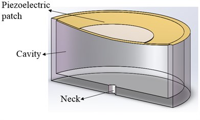
The main structure of the piezoelectric acoustic liner (Fig. 1) is the Helmholtz resonator, and one of the criteria for evaluating the acoustic performance of Helmholtz resonators is its resonant frequency [2]. The resonant frequency of the resonator can be expressed as:
where t and r are the thickness and the radius of the neck, respectively, Δt is the sum of the end correction at the inner and outer neck ends, c0=343 m/s is sound velocity in medium, and v is the cavity volume. It can be seen that cavity volume has important influence on the resonant frequency of acoustic liner.
The piezoelectric properties of piezoelectric patches directly affect the volume change of the acoustic liner, which plays an important role in the noise elimination frequency offset of the piezoelectric acoustic liner. Mainly using the inverse piezoelectric effect that the piezoelectric patch will deform when voltage is applied [3].
2. Modeling and simulation
2.1. Piezoelectric patch
Piezoelectric patch consists of substrate and ceramic (Fig. 2), under the same voltage, the deformation of the piezoelectric patch is related to the size of the piezoelectric sheet. Therefore, the finite element method is used to simulate the shape variables of different sizes under different voltages. The DC voltage is loaded on both ends of the piezoelectric ceramic and the displacement constraint is loaded on the edge of the substrate. The structure parameters are shown in the Table 1.
Fig. 2Piezoelectric patch model
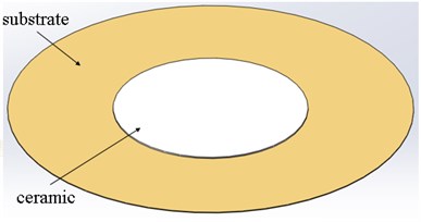
Table 1Piezoelectric patches structure parameters (mm)
Substrate diameter | Ceramic diameter | Substrate thickness | Ceramic thickness |
15 | 11 | 0.15 | 0.2 |
20 | 15 | 0.15 | 0.2 |
25 | 18 | 0.15 | 0.2 |
27 | 20 | 0.15 | 0.2 |
35 | 20 | 0.15 | 0.2 |
50 | 24 | 0.1 | 0.18 |
From the Fig. 3, it can be seen that, the piezoelectric patch has obvious deformation after applying 200 V voltage on both ends of it, displacement of edge position is 0 μm, and in a central location to achieve maximum displacement about 190 μm.
Fig. 3Results of piezoelectric plate deformation
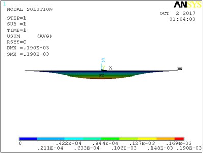
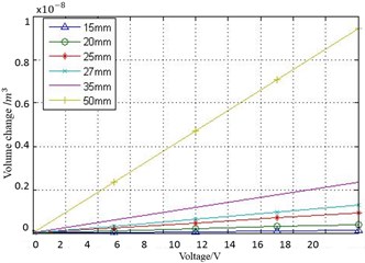
Fig. 4(a) shows the contour of piezoelectric patch deformation obtained by the surface fitting. The cavity volume change of different piezoelectric patches under 20 V voltage were compared, the result was shown in Fig. 4(b). The volume change increases with the increasing of the size of the piezoelectric patches and reached the maximum volume as 9.44 mm3 when diameter is 50 mm. So, the larger piezoelectric patch can provide a larger volume change of the cavity.
Fig. 4Calculation of the volume variation of piezoelectric patches
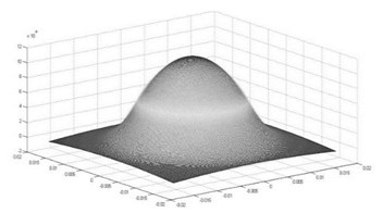
a) Result of surface fitting
b) Comparison of simulation results
2.2. Square tube with piezoelectric acoustic liner
The three-dimensional finite element method (FEM) was used to simulate the performance of piezoelectric acoustic liner. The simulation model is a rectangular pipe (51 mm×51 mm×300 mm) with piezoelectric acoustic liner (cavity: Φ=50mm, h= 1 mm; neck: Φ=1 mm, h=2 mm) on the wall of the pipeline (Fig. 5). The frequency-domain analysis is conducted to obtain the transmission loss.
Fig. 5FEM model
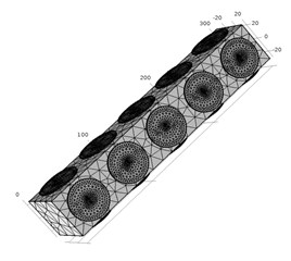
Fig. 6Transmission loss curve
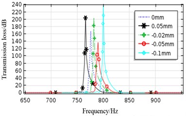
In the simulation process, piezoelectric patches deformation can be simulated by changing the height of the resonant cavity. It can be seen from the Fig. 6 that by changing the height of the chamber, the resonant frequency can be significantly offset.
3. Experiment
3.1. Piezoelectric patch center displacement test
The measurement of acoustic liner cavity volume variation is more complicated, this paper adopts the method of testing center displacement of piezoelectric patch, and the volume change of the cavity is calculated by fitting. The center displacement of piezoelectric patch was measured by laser micrometer, the test device is shown in the Fig. 7.
The center displacement of the piezoelectric patch with a diameter of 50mm is measured in different shape parameters. Two types piezoelectric patches I and II were selected.
Table 2Parameter of I and II (mm)
Type | Substrate thickness | Ceramic thickness | Ceramic diameter |
I | 0.10 | 0.18 | 24 |
II | 0.10 | 0.12 | 30 |
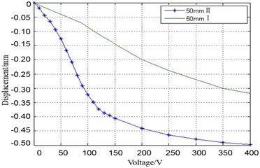
As shown in Fig.8 piezoelectric displacement test results for two kinds of parameters, 50 mm II type piezoelectric patch after the applied voltage of the variable is far greater than 50 mm I type. In 200 V DC voltage, II type piezoelectric patch center displacement can reach 450 μm, and only 200 μm I type piezoelectric patch. The results show that by increasing the diameter of piezoelectric ceramic and reducing the thickness of piezoelectric ceramic, the shape deformation of piezoelectric patch can be increased.
Fig. 7Displacement test device diagram
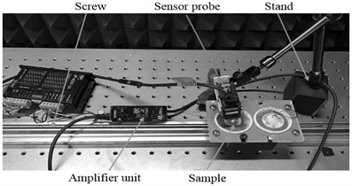
Fig. 8Piezoelectric patch test result
3.2. Acoustic performance test
The experimental facility is shown in Fig. 9, it mainly includes the loudspeaker, the pipeline, the acoustic liner and the data acquisition device. By changing the DC voltage amplitude applied on the piezoelectric patches, the volume of the acoustic liner can be changed to alter its noise elimination frequency band.
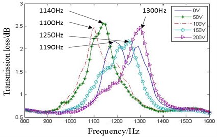
In Fig. 10, the transmission loss measurement results show that when the voltage is applied, with the deformation of the piezoelectric patches, the resonant frequency has a distinct offset. It can be seen that the piezoelectric acoustic liner has a wide noise elimination frequency band, and its range is from 1100 Hz to 1300 Hz while the voltage range of 0 V to 200 V.
Fig. 9Acoustic performance test device diagram
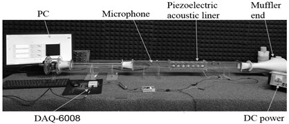
Fig. 10Transmission loss measurement results
4. Conclusions
The deformation of piezoelectric patches and the acoustic performance of piezoelectric acoustic liner are simulated and verified through experiment in this paper. The results show that when applying the 200 V DC voltage, the piezoelectric patches can realize the maximum center displacement changes of 450 μm, and the resonant frequency of the piezoelectric acoustic liner is offset by 110 Hz, the broadband attenuation is realized and the noise elimination frequency band is broaden.
References
-
Lv Haifeng, Pan Hongxia, Huang Jinying A design of tunable frequency resonant muffler. Journal of Vibration, Measurement and Diagnosis, Vol. 32, Issue 6, 2012, p. 1021-1025.
-
Han Yannan, Lv Haifeng, Geng Yanzhang, et al. Design and optimization of the piezoelectric acoustic liner structure. Piezoelectrics and Acoustooptics, Vol. 39, Issue 2, 2017, p. 220-223.
-
Wen Jianqiang, Zhang Liwang New advances in piezoelectric materials. Applied Acoustic, Vol. 32, Issue 5, 2013, p. 413-418.
-
Wu Shengju, Zhang Mingduo The Principle and Method of Acoustic Measurement. Science Press, Beijing, 2014.
About this article
This work is supported by the National Nature Science Foundation of China (NSFC, Grant No. 51305409) and Natural Science Foundation of Shanxi (Grant No. 2013021020-2).

