Abstract
Considering the limitations of the static buckling theory on the eccentric wear of sucker rod and tubing, a new dynamic analysis method for the transverse vibration of sucker rod in the tubing is proposed. Taking the axial distribution load at the rod body and the dynamic load at the bottom into account, the dynamic model of transverse vibration is established based on the space buckling configuration of rod string which regarded as the deformation excitation during the down stroke. To solve the mathematical equations, the finite difference method is used to discretize the well depth, and the Newmark-beta method is used to discretize the time. Meanwhile, a restitution coefficient is introduced to depict the change of velocity and the momentum after the collision. The result shows the phenomenon of rod-tubing collision occurs mainly in the down stroke after the rod string post buckling; the collision force from the wellhead to the bottom increases gradually, of which distributed almost along the entire well depth; and the high frequency collision occurs below the neutral point where the collision force is also the biggest. Further, the collision frequency and the collision force decrease successively from the neutral point to the wellhead direction. But during the up stroke, few collisions occur, and the collision force is also very small. The simulation model is suitable for the eccentric wear analysis of rod-tubing, and provides a new theoretical basis for the optimal allocation of the centralizer.
1. Introduction
The field statistics show that the rod-tubing eccentric wear phenomenon in the tubing is the main cause of rod-tubing failure and the pump checking in vertical wells. At present, the analysis of rod-tubing wear has followed the static buckling mechanics theory for a slender rod in the cylinder [1-3]. Namely, when the pressure load of rod at the bottom exceeds the first static buckling critical load, the sucker rod will produce buckling and cause the eccentric wear with the tubing inner wall. As we know, the sucker rod below the neutral point is considered as a compressive bar [4-7] also the theory eccentric wear area. Based on the above static buckling theory, the centralizer optimal design method anti-eccentric wear was established and used extensively [8, 9], namely, to install the centralizers below the neutral point of sucker rod string. Here, the gap distance between the centralizers was designed through taking the two adjacent centralizers unbuckled as the constraint condition. The method has effectively prevented or reduced the rod-tubing eccentric wear at the bottom of the compressive part. But surprisingly, the eccentric wear phenomenon is obviously upward in the actual oil well. Although the centralizers at the bottom sucker rod have increased the sucker rod downward hydraulic resistance and led to the neutral point and the eccentric wear points a small shift, the actual eccentric wear position is significantly higher than the theoretical neutral point according to the variation of the actual measurement suspended indicator diagram. So, the current static buckling theory of sucker rod cannot give the reasonable explanation of the rod-tubing wear phenomenon.
Indeed, the centralizers equipped at the bottom sucker rod have prevented or alleviated effectively the bottom rod-tubing wear, but not prevented the rod buckling, so the whole sucker rod is still in the state of buckling. Considering the radial clearance between the centralizer and the inner wall of the tubing, the buckling configuration of the sucker rod string has been changed after centralizers allocated. Obviously, for the sucker rod in vertical wells, the overall sucker rod is buckled when the resistance of the rod string at the bottom is bigger than the critical buckling load no matter whether the centralizers are equipped or not. Namely, the rod string has generated transverse displacement in this case [10-12]. In the author’s opinion, the transverse buckling deformation of the sucker rod stimulates the sucker rod to produce the transverse vibration in the tubing and cause the collision friction with the tubing inner wall. The collision friction below the neutral point is more serious, and above the neutral point or even the whole wells also produce rod-tubing collision. So, after the rod string below the neutral point equipped with centralizers, the rod above the neutral point has become the new weak point and produce eccentric wear or even wear off.
The rod string dynamics in petroleum engineering had been studied extensively by many experts and scholars: the longitudinal vibration of sucker rod [13, 14], the transverse vibration of traditional pressure bar [15, 16] and moving beam [17, 18], the transverse forced vibration of riser under tension [19-21], the transverse vibration and collision problems for wellbore under fluctuating pressure [22-25]. However, the research on the transverse vibration triggered by the buckling deformation excitation seems to have not been discovered so far. In addition, the following cases are considered: (1) The environmental load of sucker rod is complex, there is not only the non-uniform axial distribution force, but the bottom load varying with the bump speed, which shows the tension as well as the pressure state and the tensile force dominated. (2) The transverse vibration of sucker rod is triggered, and the rod collides with the tubing inner wall with the collision point changing with time. The above-mentioned complex load is considered globally in this paper, further, the simulation method of sucker rod transverse vibration in the tubing and the eccentric wear of rod-tubing are established. The method provides a new theoretical basis for the eccentric wear analysis of rod-tubing and optimal configuration of the centralizer.
2. Mechanical model
For the convenience of study, the following assumptions and simplifications are considered:
1) The sucker rod string is an elastic rod, and the wellbore center line is coincident with the rod string center line in the vertical well.
2) To establish the coordinate system from zero point of the wellhead, the axial distribution load of sucker rod in well depth x is q(x). The bottom of sucker rod is subjected to periodic loading P(t).
3) The sucker rod is a homogeneous single stage rod, and the influence of the connectors and centralizers is neglected.
4) The influence of the longitudinal vibration and torsional vibration on the transverse vibration is not considered.
5) The space buckling configuration of rod string at a given moment is considered as the deformation excitation of rod string.
Under the above assumptions, the transverse vibration mechanics model of sucker rod is shown in Fig. 1. The buckling deformation diagram is shown in Fig. 1(b).
Fig. 1Transverse bending mechanics model of sucker rod
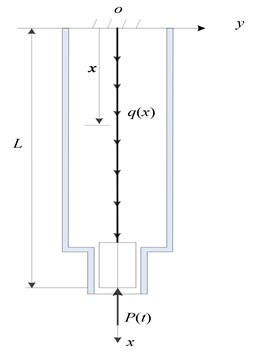
a) Mechanical model
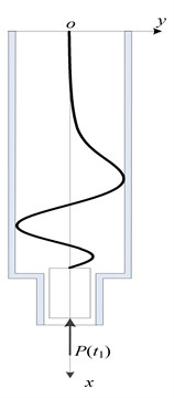
b) Buckling configuration
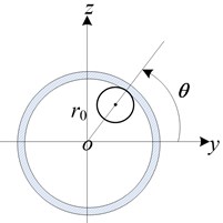
c) Rod geometric position
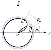
d) Top view
The bottom load of sucker rod P(t) adopts the result of the wave equation for the longitudinal vibration. The wave equation [26] is expressed by:
3. Mathematical model
3.1. Transverse vibration equation of sucker rod string
Under the assumption that the viscous damping force in oil for the sucker rod at any point xi in the transverse direction y and z is υ∂yi/∂t. By the force and moment balance of rod string in the xoy plane and xoz plane, the mathematical equation is obtained as follows:
3.2. Boundary conditions
The displacement and the rotation angle at the top of sucker rod string are constrained by the wellhead, so the top boundary condition is simplified as a fixed end. Similarly, the displacement and the rotation angle at the bottom are restrained by the pump barrel, so the bottom boundary condition is simplified as a sliding fixed end. Thus, the boundary conditions at both ends of sucker rod can be expressed by:
3.3. Initial condition and deformation excitation
Assuming that the initial state of sucker rod string is natural and static, and the suspension point of rod string is at the bottom dead center, the initial condition of the whole system at time t=t0 is satisfied by:
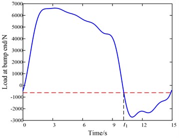
The space buckling of sucker rod will occur at a moment during the down stroke. Here the buckling configuration is regarded as the periodic deformation excitation for the rod transverse vibration. In other words, when P(t1) exceeds the space buckling critical load at time t1 during the down stroke, a continuous contact area of the rod-tubing starts to appear, and the space buckling configuration at this time is just the deformation excitation of rod string transverse vibration. Considering the energy for each period will be partly dissipated due to the system damping, the deformation excitation will be applied once a period at time t1+nT according to the superposition principle of small deformation.
3.4. Collision condition
Taking the ith node of the sucker rod as an example, the node is regarded as a particle with the quality me whose coordinate is (uty, utz) on the cross section. When the transverse displacement is satisfied by |√u2ty+u2tz|≥r0, the rod collides with the inner wall of tubing. During the transient process, the radial velocity is reversed in direction with a weaken reverse speed due to the frontal collision, while the tangential velocity are changeless in magnitude and direction. After the collision, the node displacement falls on the inner circumference of the tubing as shown in Fig. 2. Correspondingly, the node displacement collision conditions can be given by:
where:
Fig. 2Velocity change during the collision
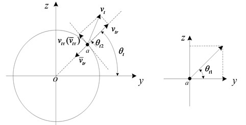
Taking the node in the first quadrant as an example, shown in Fig. 2, the relationship of velocity change before and after collision is analyzed. Since there is only the change in the radial velocity during the collision, the relationship between the radial velocity and the tangential velocity can be satisfied by:
The velocity after the collision can be regarded as the initial velocity at the next moment through decomposing it into two coordinate directions. Therefore, when θt1≥θt, the velocity after the collision can be expressed by:
When θt1<θt, the post collision velocity will become, as follows:
The collision recovery coefficient γi (0<γi< 1) is related to the material of two collision bodies, steel to steel is 0.56, iron to lead is 0.14, steel to the naked rock is 0.1 [27].
Though the collision force generated by the rod-tubing collision is extremely large and the instantaneous value is difficult to measure in the process of collision, the dynamic impulse S can be used to estimate the impact strength, which is satisfied by the impulse theorem. When the precision of calculation is not required perfectly, the collision time τ related closely to two solid materials can be determined by the empirical value obtained by experiments [28]. In this paper, the material of sucker rod and tubing all belongs to the alloy steel and τ can be chosen as 0.03 s. Therefore, the average value of collision force during the collision time τ by the impulse theorem can be obtained by:
The collision process is divided into the extrusion time t1i and recovery time t2i. It is assumed that the collision time is just a time step, the following equation can be satisfied:
4. Simulation method
Eq. (4) is a variable-coefficient and higher-order differential equation with the variable t and x being coupled together. Therefore, the analytic solution cannot be obtained by using the separation variable method. In this paper, the numerical solutions are obtained by combination of two methods of Newmark-beta method and difference method [29-33].
First, the finite difference method is used to separate the space variable x and Newmark-beta method is used to discretize the time variable t. The whole sucker rod is divided into n elements and n+1 nodes, the corresponding nodes number is i= 0, 1,…, N. The space node step is h, the time step is t.
The difference expressions about two fixed boundary nodes can be obtained by the central difference method, as follows:
Taking the xoy plane as an example, the all-order derivative in the y direction is rewritten by the difference form. The difference forms of the fourth-order derivative on each node can be expressed by:
Similarly, the difference forms of first-order and second-order derivative on each node can be expressed respectively by:
The Newmark-beta method is used to discretize the time, and then the following assumptions are made:
where, β and γ are the adjustable parameters according to the integral accuracy and stability requirements. When β≥0.5 and γ≥0.25(0.5+β)2, the Newmark-beta method is an unconditionally stable format. Here we let β=0.5, γ=0.25. {˙y}t+Δt and {¨y}t+Δt by Eq. (16) can be obtained by:
The vibration differential equation at time t+∆ according to the Newmark-beta method can be expressed as:
Substituting Eqs. (16-17) into Eq. (18), the equation about can be obtained by:
where:
can be obtained by solving Eq. (19). and can also be got by Eq. (17). It is assumed that , constant, we give out the discrete form of Eq. (2) in the following:
where represents the transverse displacement of th space node and th time node on the axis.
5. Engineering simulation examples
5.1. Basic parameters
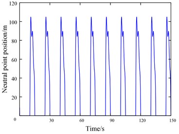
The basic simulation parameters are listed in Table 1. In addition, the change rule of the bottom load with time is shown in Fig. 3(a), the corresponding neutral point position is shown in Fig. 3(b), the deformation excitation of buckling configuration is applied at time . Among these parameters, the bottom load can be transformed into an analytical expression about time by Fourier series transform.
Table 1Simulation parameters
Number | Parameters / unit | Value |
1 | Diameter of sucker rod string / m | 0.025 |
2 | Rod length / m | 1000 |
3 | Density of rod / (kg/m3) | 7860 |
4 | Elasticity modulus / (GPa) | 209 |
5 | Radial clearance rod-tubing / m | 0.01 |
6 | Damping coefficient / (N·s/m2) | 0.05 |
7 | Period time / s | 15 |
5.2. Simulation result analysis and experiment verification
Substituting the above basic parameters into the simulation model, we can get the following simulation results.
Fig. 3The curve of pump load and the neutral point position with time
a) Load at the bump end
b) Neutral point positions
5.2.1. Variation law of collision force
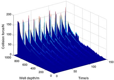
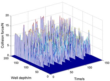
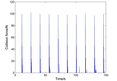
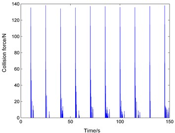
The variation regularity of collision force with the well depth and time in 10 full cycles and 150 seconds is obtained in Fig. 4 and Fig. 5.
Fig. 4 shows that (1) the collision force is distributed almost along the whole well depth. In each movement period, the collision occurs mainly on the down stroke, and the collision force increases with the increase of the well depth and reaches the largest near the bottom. (2) Under the larger damping coefficient, the collision force shows approximately the periodic variation law. (3) The collision force each stroke is in the same or close level with the error of curve peak value being shown within 15 %.
From Fig. 5, it can be found that the collision frequency is higher and the collision force is bigger from the neutral point to the bottom than above the neutral point. The collision force and collision frequencies become smaller and smaller from the neutral point to the wellhead.
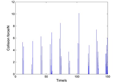
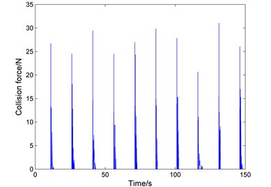
Fig. 6 further shows: (1) The most fierce collision point is not near the neutral point but below the neutral point near the bump end. (2) The maximum collision force below the neutral point is almost the same at the corresponding position with different periods. (3) The collision points are very few and the collision force is weak during down stroke.
In all, the collision mainly occurs during down stroke with the collision force almost being distributed throughout the whole well. The collision below the neutral point is the fiercest and collision force is the biggest. The simulation results have well explained why the eccentric wear phenomenon still happens although centralizers installed below the neutral point. Indeed, the eccentric wear phenomenon at the bottom or below neutral point has been improved well after centralizers installed, but disappointingly, the position points above the neutral point become the new weakness points.
Fig. 4The curve of collision force with the well depth and time
a) Well depth 0-1000 m
b) Well depth 0-200 m
Fig. 5The local curve of collision force with well depth and time (45-60 s)
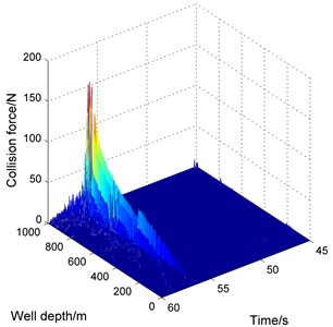
Fig. 6The curves of collision force with time in different depths
a)100 m
b)400 m
c)900 m
d)940 m
5.2.2. Transverse vibration trajectory
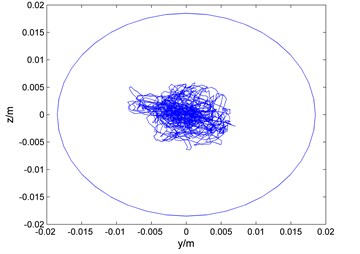
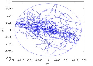
Fig. 7 shows that the transverse trajectory within = 1-150 s in different well depth points. The sucker rod does not collide with the tubing wall near 20 meters from the wellhead with the low amplitude vibration around the center of the well. Near 100 meters from the wellhead, the less collision has appeared between the rod and the tubing. Then the stronger and stronger collision is produced from 400 meters to the bottom of well with the most intense vibration in 960 meters. It can be deduced that the regularity of the rod-tubing contact or collision area varies from free-collision to weak-collision, and then strong-collision from the wellhead to the bottom bump. Except tens of meters near the wellhead, all the rest position points have produced rod-tubing lateral collision, and the collision is more and more intense with the increase of well depth. Different from the static buckling theory, the rod section above neutral point also produces the relatively strong rod-tubing collision.
Fig. 7The curves of movement trajectory in different depths
a)20 m
b)100 m
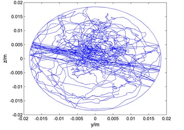
c)400 m
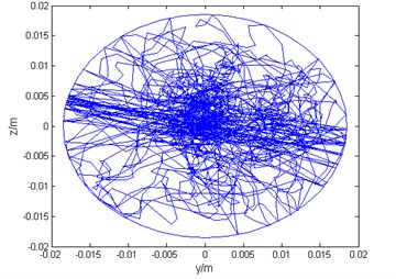
d)900 m
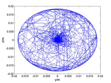
e)960 m
5.2.3. Bending configuration at different times
Fig. 8 shows that the bending deformation of sucker rod at different times in the same period. Before the buckling deformation excitation is applied, the rod also produces small amplitude transverse vibration displacement and small collision probability with the inner wall of tubing. After the buckling deformation excitation is applied, the rod string has produced strong space transverse vibration and almost continuous collision phenomenon below the neutral point. It is known that the load acted at the bottom of the rod string will change from negative to positive, namely pressure state to tension after the down stroke, the buckling of the rod string will disappear. However, it can be found from Fig. 8(a-d) that the residual deformation of transverse vibration produced by the buckling deformation excitation during the previous cycle will transmit toward the wellhead in the form of the gradually weakening spiral wave until the buckling configuration excitation is applied again, and so on reciprocating periodically.
Fig. 8Bending configuration of the entire rod string at different times during a period
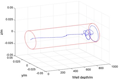
a) At 15 s initial during up stroke
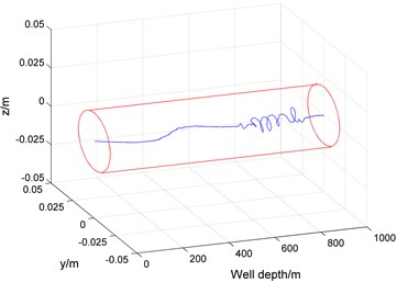
b) At 18 s early during up stroke
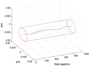
c) At 24 s before deformation excitation applied
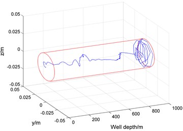
d) At 27 s after deformation excitation applied
Fig. 9The eccentric wear of rod string in oil field
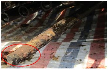
a) The 67th rod worn off in no. X2 well
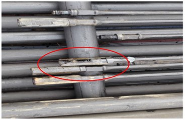
b) The 102-150th connectors worn seriously in no. X8 well
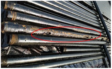
c) The tubing worn out in no. X5 well
5.2.4. Experiment verification
In order to further validate the correctness of the simulation results in this paper, the comparison of three groups of data is shown in Table 2: the measured data of pump inspection in an oilfield in early 2017, a traditional static method and the result in this paper. Further, the eccentric wear of rod string in oil field, which has been equipped with the centralizer in the middle and lower part of sucker rod, is shown in Fig. 9. We can see from the data the eccentric wear areas of rod-tubing in the oil field have a great dispersion without obvious regularity. From the wellhead to the pump, the eccentric wear of rod-tubing can happen anywhere, which is determined by many factors, such as wellbore conditions, swabbing parameters and so on. The simulation results about the rod-tubing eccentric wear in the last column in Table 2 is in fully consistent with the experimental results of last third column, however, the results obtained by the static method in last second column are partly consistent with the experimental results. Therefore, we can say that the simulation method in this paper is correct and more convincing. In the future, we will also take some advanced experimental method to test the response of this structure to validate the numerical simulation further, such as wireless sensor networks [34-39].
Table 2Experiment results verification
Number | Bump diameter /(mm) | Pump depth /(m) | Stroke /(m) | Frequency / (1/min) | Combining form of rod string /(mm) ×/(m) | Serious wear areas or break point measured /(m) | Wear area simulated by static method /(m) | Wear area simulated in this paper /(m) |
X1 | 38 | 1699.62 | 3 | 2.5 | 25×500+22×400+19×(-900) | 1336 | 1354- | 130- |
X2 | 44 | 1496.15 | 4 | 2.9 | 22×596+19 ×(-596) | 960-1392 | 1190- | 120- |
X3 | 57 | 1003.15 | 4.2 | 3 | 25×250+22×300+19×(-550) | 560-976 | 870- | 82- |
X4 | 70 | 902.31 | 4.8 | 2 | 25×200+22×400+19×(-600) | 536 | 795- | 71- |
X5 | 38 | 1511.47 | 3 | 2.5 | 25×400+22×500+19×(-900) | 320-640, 880-1200 | 1201- | 123- |
X6 | 44 | 1596.35 | 4.2 | 2.1 | 25×400+22×700+19×(-1100) | 208 | 1253- | 119- |
X7 | 32 | 1993.1 | 5 | 1.2 | 25×800+22×700+19×(-1500) | 800-1900 | 1560- | 140- |
X8 | 32 | 1864.26 | 4.8 | 1.7 | 25×600+22×650+19×(-1350) | 400-1200 | 1452- | 136- |
6. Conclusions
The transverse vibration model of sucker rod string under the space buckling deformation excitation is established in the tubing. Based on the model, the finite difference method and Newmark-beta method are used to solve the equations, and the collision effect between rod and tubing being is fully considered. The nonlinear dynamics simulation of rod-tubing collision under transverse vibration in the vertical well pumping is realized well.
The phenomenon of rod-tubing collision caused by the transverse vibration occurs almost along the whole well depth. The collision force increases gradually from the wellhead to the bottom. Collisions below neutral point are most fierce, and gradually decrease from the neutral point to the wellhead.
The phenomenon of rod-tubing collision occurs mainly during the down stroke and after post buckling with the high collision frequency and large collision force. However, the collision phenomenon is few and collision force is small during the up stroke.
The periodic transverse vibration is completely described with a complete cycle in this paper. The residual deformation of transverse vibration produced due to the buckling deformation excitation during the previous cycle will transmit toward the wellhead in the form of the gradually weakening spiral wave until the buckling configuration excitation is applied again.
A new method is provided for analyzing the rod-tubing eccentric wear. The simulation results are in good agreement with the engineering practice and better explain the rod-tubing eccentric wear not only occurs below the neutral point also the above the neutral point. So, the centralizers are positioned below the neutral point can effectively prevent or reduce eccentric wear of rod-tubing at the bottom compressed section of rod string, but after the centralizers are positioned, the position points above the neutral point even near the wellhead become the new weak points who have not get the protection of the centralizer. The simulation model of transverse vibration excited by the buckling deformation of sucker rod string is suitable for the eccentric wear analysis of rod and tubing, and provides a new theoretical basis for the optimal allocation of the centralizer.
References
-
Lubinski A. A Study of the Buckling of Rotary Drilling String. Drilling and Production Practice, 1950, p. 178-214.
-
Gao G. H., Li Q., Zhang J. R. Buckling analysis of pipe string in a vertical bore hole. Xi’an Petroleum Institute, Vol. 11, Issue 1, 1996, p. 33-35.
-
Huang W. J., Gao D. L., Liu Y. H. A study of tubular string buckling in vertical wells. International Journal of Mechanical Sciences, Vol. 118, 2016, p. 231-253.
-
Dong S. M. Mechanical analysis on causes of worn rod string and tubing of rod pumping wells in the water-flooding oilfield. Acta Petrolei Sinica, Vol. 24, Issue 4, 2003, p. 108-112.
-
Wang H. M., Wu J. H., Chen X. M., et al. Rod, tubing mechanism and control technology. Journal of Southwest Petroleum Institute, Vol. 28, Issue 5, 2006, p. 99-101.
-
Liu X. F., Wang C. S., Liu C. H., et al. Development of mechanical model for rod string based on well liquid flow characteristics. Journal of Mechanical Engineering, Vol. 49, Issue 14, 2013, p. 176-181.
-
Liu H., Hao Z. X., Wang L. G., et al. Current technical status and development trend of artificial lift. Acta Petrolei Sinica, Vol. 367, Issue 11, 2015, p. 1441-1448.
-
Tan C. J., Xu B. Y., Gao D. L. Study on the placement of centralizers on pipe string in straight well. Oil Drilling and Production Technology, Vol. 22, Issue 3, 2000, p. 8-9.
-
Shi N. N., Li J. Q. Design and computation for installing interval between centralizers of sucker-rod strings in vertical wells. Petroleum Drilling Techniques, Vol. 35, Issue 2, 2007, p. 59-61.
-
Mitchell R. F., Miska S. Helical buckling of pipe with connectors and torque. SPE Drilling and Completion, Vol. 21, Issue 2, 2006, p. 108-115.
-
Huang W. J., Gao D. L. Helical buckling of a thin rod with connectors constrained in a cylinder. International Journal of Mechanical Sciences, Vol. 84, 2014, p. 189-198.
-
Huang W. J., Gao D. L., Liu Y. H. Inter-helical and intra-helical buckling analyses of tubular strings with connectors in horizontal wellbores. Journal of Petroleum Science and Engineering, Vol. 152, 2017, p. 182-192.
-
Dong S. M., Yao C. D. Doubting the resonance condition of the longitudinal vibration of the sucker rod string introduced by APIRPLLL and improving of the mechanical modeling. Journal of Vibration Engineering, Vol. 16, Issue 3, 2003, p. 389-392.
-
Dong S. M., Zhao L. P., Wang S. J., et al. Simulation models of longitudinal vibration of sucker rod string of polymer flooding rod pumping systems. Journal of System Simulation, Vol. 20, Issue 2, 2008, p. 309-313.
-
Zhao W. D., Yang Y. P., Li X. L., et al. The transverse vibration and buckling of a compressive bar on elastic foundation subjected to harmonic excitation. Chinese Journal of Applied Mechanics, Vol. 32, Issue 4, 2015, p. 642-646.
-
Morozov N. F., Tovstik P. E. Transverse rod vibrations under a short-term longitudinal impact. Doklady Physics, Vol. 58, Issue 9, 2013, p. 387-391.
-
Yang X., Chen H. B. Vibration characteristics of an axially moving beam under thermal shocks. Journal of Vibration and shock, Vol. 36, Issue 1, 2017, p. 8-15.
-
Duan Y. C., Wang J. P., Wang J. Q., et al. Theoretical and experimental study on the transverse vibration properties of an axially moving nested cantilever beam. Journal of Sound and Vibration, Vol. 333, Issue 13, 2014, p. 2885-2897.
-
Dong S. M., Lv Q. D., Zhang N. Analysis of transverse free vibration of riser effected by distribution of axial force. Mechanics in Engineering, Vol. 38, Issue 5, 2016, p. 538-543.
-
Li Z. F., Wang P., Zhao M., et al. Transverse vibration analysis of the riser in deep water. Source: Open Petroleum Engineering Journal, Vol. 8, Issue 1, 2015, p. 38-44.
-
Blevins R. D., Coughran C. S., Utt M. E., et al. Drilling-induced riser vibration. International Society of Offshore and Polar Engineers, Vol. 27, Issue 3, 2017, p. 232-238.
-
Ren F. S., Chen S. L., Yao Z. G. Vibration response analysis of slender flexible revolving beam under axial load. China Mechanical Engineering, Vol. 24, Issue 24, 2013, p. 3392-3396.
-
Zhu X. H., Hu Z. Q. Lateral vibration characteristics analysis of a bottom hole assembly. Journal of Vibration and Shock, Vol. 33, Issue 17, 2014, p. 90-93.
-
Zhu W., Di Q. Effect of prebent deflection on lateral vibration of stabilized drill collars. Society of Petroleum Engineers, Vol. 16, Issue 1, 2011, p. 200-216.
-
Bang J. Quantification of wellbore collision probability by novel analytic methods. Proceeding of the SPE/IADC Drilling Conference and Exhibition, Hague, Netherlands, 2017.
-
Dong S. M. Computer Simulation of Dynamic Parameters of Rod Pumping System Optimization. Petroleum Industry Press, Beijing, 2003.
-
Zhu X. H., Tong H., Liu Q. Y., et al. Research on the dynamic boundary condition between revolving drill string and borehole wall. China Mechanical Engineering, Vol. 18, Issue 15, 2007, p. 1833-1837.
-
Song X. H., Li W. Crashworthiness numerical simulation of material properties on vehicle steering mast. Journal of Chongqing Jiaotong University (Natural Science), Vol. 31, Issue 4, 2012, p. 866-868.
-
Cui K., Zhao T. T. Unsaturated dynamic constitutive model under cyclic loading. Cluster Computing, Vol. 20, Issue 4, 2017, p. 2869-2879.
-
Yang A., Han Y., Pan Y., et al. Optimum surface roughness prediction for titanium alloy by adopting response surface methodology. Results in Physics, Vol. 7, 2017, p. 1046-1050.
-
Cui K., Yang W., Gou H. Experimental research and finite element analysis on the dynamic characteristics of concrete steel bridges with multi-cracks. Journal of Vibroengineering, Vol. 19, Issue 6, 2017, p. 4198-4209.
-
Sun Y., Qiang H., Mei X., et al. Modified repetitive learning control with unidirectional control input for uncertain nonlinear systems. Neural Computing and Applications, 2017, https://doi.org/10.1007/s00521-017-2983-y.
-
Wei W., Fan X., Song H., et al. Imperfect information dynamic Stackelberg game based resource allocation using hidden Markov for cloud computing. IEEE Transactions on Services Computing, Vol. 99, 2016, p. 1-13.
-
Li J., Deng G., Luo C., et al. A hybrid path planning method in unmanned air/ground vehicle (UAV/UGV) cooperative systems. IEEE Transactions on Vehicular Technology, Vol. 65, Issue 12, 2016, p. 9585-9596.
-
Li J. Q., Li W. L., Deng G. Q., et al. Continuous-behavior and discrete-time combined control for linear induction motor-based urban rail transit. IEEE Transactions on Magnetics, Vol. 52, Issue 7, 2016, p. 1-4.
-
Yang K., Yang J., Wu J. S., et al. Performance analysis of DF cooperative diversity system with OSTBC over spatially correlated Nakagami-m fading channels. IEEE Transactions on Vehicular Technology, Vol. 63, Issue 3, 2014, p. 1270-1281.
-
Du J. F., Xiao P., Wu J. S., et al. Design of isotropic orthogonal transform algorithm-based multicarrier systems with blind channel estimation. IET Communications, Vol. 6, Issue 16, 2012, p. 2695-2704.
-
Li J., He S., Ming Z., et al. An intelligent wireless sensor networks system with multiple servers communication. International Journal of Distributed Sensor Networks, Vol. 11, Issue 8, 2015, p. 960173.
-
Wei W., Song H., Li W., et al. Gradient-driven parking navigation using a continuous information potential field based on wireless sensor network. Information Sciences, Vol. 408, 2017, p. 100-114.
Cited by
About this article
This project is supported by the National Natural Science Foundation of China (Grant No. 51174175) and Hebei Province Natural Science Foundation of China (Grant No. E201703101).

