Abstract
Fatigure in rolling element bearings results in spalling of the raceways or rolling elements which is the most common bearing fault. The size of the spalling area, however, has close relationship with dual-impulse behavior produced by a localized surface spall. Based on the Hertzian contact theory and investigation of the excitation mechanism of dual-impulse behavior excited by a localized surface spall, a new coupled non-linear dynamic model of the ball bearing with a localized surface spall on outer race is developed, which considers the time-varying displacement and contact force excitation. The solution to the differential equations is obtained applying the Runge-Kutta numerical integral method. The time interval of dual-impulse behavior is investigated in this paper. Comparisons of the stimulated and theoretical results and the experimental and theoretical results show the effectiveness of the proposed model.
1. Introduction
Rolling element bearings are widely applied in the most majority of rotary machinery due to their low friction coefficient, efficient load transmission capacity, and reliability. And the failure of bearings are the most common reason for machine breakdowns. A dual-impulse response will happen when a rolling element moves through the spalled area under cyclic loads [1]. Importantly, this dual-impulse behavior provides a completely reliable and novel method for spalling fault detection, fault diagnosis and life prediction. And therefore, it is crucial to investigate the dual-impulse behavior produced by a spall on inner or outer races of a ball bearing.
Over the past decades, some studies have been carried out for the dual-impulse behavior produced by a spall. The earliest research of bearing fault characterization and quantification using vibration analysis was the Ph.D. study by Epps [2] in 1991. He reported that the vibration characteristics associated with rolling elements passage over a raceway spall could consist of a step response for the balls entry into the spall and an impulse response for the balls impact on the trailing edge of the spall. The step response is associated with lower frequency content than the impulse response in which broad frequency content including high-frequency resonance oscillations can be evident. Whilst he pointed out that the size of the flaking area could be estimated if each response event (i.e., step and impulse response) was visible in the time-domain series collected from a rolling element bearing in presence of a localized surface fault. He only did analyze, however, the two responses in vibration signal, and didn’t carry out profound investigations for the generation mechanism of the two responses and develop a dynamic model which valued the two impulse responses. On this basis, Sawalhi and Randall [1] indicated that the acceleration signals resulting from the entry of the rolling element into the spall zone and exit from it were of different characteristics and the amplitudes of the two events were always greatly different. Furthermore, they developed an analytical model involving the two events to describe the observed phenomena. Unfortunately, the spectral characteristics of the vibration signal involving the two events were not further investigated and they did not, simultaneously, proposed a dynamic model for describing dual-impulse behavior. Ming et al. [3] did a further analysis for dual-impulse behavior. In their paper, the acoustic emission (AE) signal was applied to evaluate the size of the single spall. Considering the sensitivity of the AE signal to the incipient fault detection and related theories. Based on the hypothesis that the AE signal is composed of two events for each passage of the rolling element across the spall area, they proposed an analytical model, i.e., dual-impulse response model to describe the AE signal. Then, an averaged dual-impulse interval determining method is developed to estimate the size of the spall. However, a dynamic model based on the generation mechanism of dual-impulse behavior was not developed. These above-mentioned studies involve only mechanism analyses of dual-impulse behavior given rise to by a spall on raceways of a bearing, however, it is worth mentioning here that a dynamic model for dual-impulse behavior has not been proposed and established.
Considering the above-mentioned current problems. As a result, it is great important and practical to conduct a research on dynamic modeling for describing dual-impulse behavior, which provides a theoretical basis for the study of dual-impulse behavior exited by a localized defect in the ball bearing and spall size assessment.
2. Time-vary deflection excitation
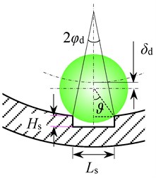
When a spall occurs on the outer race of the rolling element, the total deflection within the loaded zone of the rolling element bearing at the contact of the rolling element and local surface spall will increase, i.e., the additional displacement δd will be considered into the total deflection. When the center of ball approaches to the spall area, the additional displacement of the ball remains zero. However, when it passes over the spall, the additional displacement increase. It reaches its maximum value when the ball reaches at the center of the spall zone. And then, the additional displacement decreases from maximum to zero as the ball rolls from the spall center to other edge of the spall. And thereafter the additional displacement finally becomes zero as the ball exits the spall area.
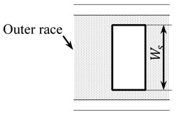
Fig. 1a) Sketch of the additional deflection when the rolling element passes across the spall area, b) top view of the spall area
a)
b)
Based on the above-mentioned analysis and the geometry of the rolling element bearing, considering the mathematical model of Liu et al. [6]. As a result, a time-vary deflection model which the spall is modeled as a circumferential half sinusoidal wave of the defective ball bearing presented in this paper:
where Db, is the diameter of the ball, Ls is the spall length, ϑ is the ball-spall contact angle as shown in Fig. 1(a); ϕs denotes the angular position of the spall center with respect to the x axis, it can be considered 1.5π in this paper; θl is the angular position of the rolling element with respect to the x axis, can be defined as follows:
where θ0 is the initial angular offset of the first rolling element to the x axis, l denotes the lth rolling element of the bearing, Nb is the total number of the rolling elements; ωc is the cage speed, which can be written by the following relation [5]:
where ωs is the rotor speed, γ=Dbcosα/Dm denotes the intermediate variable.
Considering the above-mentioned mathematical formulation of additional deflection, the time-varying deflection excitation model can be given as:
where Cd is the internal diametral clearance of the rolling element bearing, λl denotes the ball-spall contact parameter of the lth rolling element, can be written as follows:
where φd is the size of the spall with respect to the outer race center, as illustrated in Fig. 1(a).
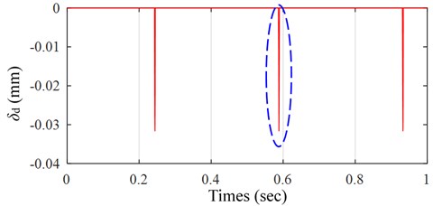
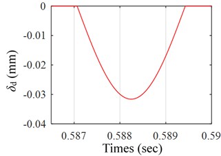
Fig. 2 illustrates the simulated result of time-varying displacement excitation model as mentioned above within 1 second, it shows the motion locuses of a rolling elements when it rolls over the spall area. It is worth noting that the simulated result only presents the variation of the additional deflection. For the purpose of observing clearly the change tendency of the motion locus of the ball, as a result, Fig. 2(b) presents the enlarged view of the encircled zone of Fig. 2(a).
Fig. 2a) Time-varying displacement excitation of the first ball, b) the zoomed-in view of the encircled zone of a)
a)
b)
3. Dynamic modeling
Based on the Hertzian elastic contact theory, the non-linear relation of load-deformation is written as follows [5]:
where n is the load-deflection exponent, n= 1.5 for a ball bearing and 10/9 for a roller bearing. δ is the radial deflection or contact deformation, K denotes the total contact stiffness coefficient between the rolling element and the bearing races or constant for Hertzian contact elastic deformation, it can be given by [5]:
where Kin and Kou denote the contact stiffness’s between the ball and the inner race, and that between the ball and the outer race, respectively. For ball bearing, the contact stiffness can be calculated by the following relation [5]:
in which ∑ρ denotes the curvature sum of the contact of a ball and the inner race or a ball and the outer race, Ee is the equivalent elastic modulus, ζ1 and ζ2 denote the first and second kind of elliptical integral, respectively; and e is the elliptical eccentricity parameter. ∑ρ, Ee, ζ1, ζ2 and e can be calculated by the methods presented in Ref. [5].
Since the Hertzian forces occur only when there is a contact deformation between the rolling element and the bearing races within loaded zone of the bearing. Consequently, the contact force between a ball and races can be defined as follows:
As a result of the total contact force which between a rolling element and the races is the sum of the contact force from each of the rolling elements, so, resolving the total contact force along the x and y axis, the components of contact forces can be determined by the following relation:
To investigate the dual-impulse behavior of the rolling element bearing with a localized surface spall on the outer race, the contact between the ball and the bearing races is considered as a spring-mass system. Based on the hypotheses made in Ref. [7, 8] and the model which was first developed by Sunnersjӧ [9], a novel dynamic model which considers the time-varying deflection excitation is proposed in this paper to study the dual-impulse behavior produced by the spall located on the outer race of the bearing. The non-linear differential equations of describing dual-impulse behavior are obtained as follows:
where parameter Meq denotes the equivalent mass of the shaft and the inner race of the rolling element bearing, C is the damping coefficient; Wx and Wy are the components of external force acting on the shaft, respectively, x and y are the displacement response in the x and y directions; χl is the loading zone parameter of the lth rolling element, χl= 1 for δl≥ 0 and 0 for δl< 0.
4. Results and discussion
4.1. Simulated result
The non-linear dynamic differential equations are solved numerically applying the Runge-Kutta fourth-order numerical integration scheme. The time step Δt= 5×10⁻⁶ s, the specified time period for solution of Eqs. (12) and (13) is 1 s, the equivalent mass Meq is 0.56 kg, the damping coefficient C of the mass-spring system was chosen to be 2200 N∙s/m, the speed ωs of the rotor is 439.01 RPM, the components of radial force acting on the rotor Wx and Wy are 45 N and 0 N, respectively. Assuming the circumferential length Ls of the spall is 1 mm. The initial velocities are assumed to be zero, i.e., ˙x= 0 and ˙y= 0, initial displacements are set to the following values: x0= 1 µm and y0= 1 µm. And the input parameters of the dynamic model proposed in this paper are listed in Table 1.
Table 1Dimensions of the hybrid ceramic ball bearing
Parameters | Value |
Pitch diameter (Dm), mm | 38.500 |
Ball diameter (Db), mm | 7.938 |
Number of ball (Nb) | 9.000 |
Inner race diameter (Din), mm | 30.562 |
Outer race diameter (Dou), mm | 46.438 |
Internal diametrical clearance (Cd), µm | 1.000 |
Contact angle (α), degree | 0.000 |
4.2. Experimental result
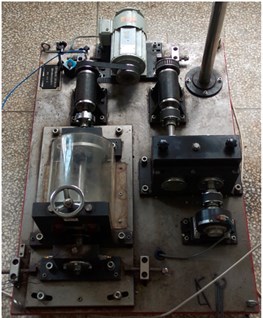
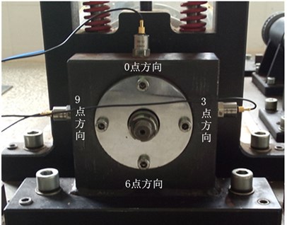
To invalidate the effectiveness of the proposed dynamic model for describing the duan-impulse behavior, experiment is carried out on the fault analog experimental test rig QPZZ-II, as shown in Fig. 3.
Fig. 3a) Test rig of QPZZ-II, b) faulty rolling element bearing with bearing housing
a)
b)
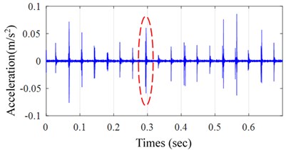
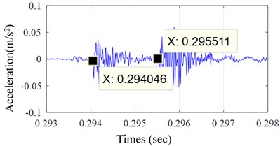
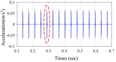
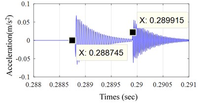
Fig. 4 illustrates the experimental result, from which a typical dual-impulse phenomenon can be observed. For the purpose of observing clear the dual-impulse phenomenon and calculating the time interval of dual-impulse behavior, a enlarged view of dual-impulse behavior of the encircled zone of Fig. 4(a) is shown in Fig. 4(b).
Fig. 5 shows the simulated result, from which we can observe the typical dual-impulse phenomenon in Fig. 5(b).
Table 2Comparison of dual-impulse time interval (DTI)
Comparison of simulated and theoretical DTI | Comparison of experimental and theoretical DTI | ||||
Simulated DTI | Theoretical DTI | Relative error (%) | Experimental DTI | Theoretical DTI | Relative error (%) |
0.00117 | 0.00120 | 2.5 % | 0.001464 | 0.00120 | 22 % |
Fig. 4a) Measured vibration signal, b) zoomed-in view of the encircled zone of a)
a)
b)
Fig. 5a) Simulated vibration signal, b) enlarged view of the encircled zone of a)
a)
b)
5. Conclusions
In this paper, a novel dynamic model for describing dual-impulse behavior is developed which considers the time-varying deflection excitation excited by the spall on outer race of bearing. Comparisons of simulated and theoretical DTI and experimental and theoretical DTI show the effectiveness of the proposed dynamic model. As a result, the developed dynamic model provides a theoretical basis for monitoring and fault diagnosis of rolling element bearing.
References
-
Sawalhi N., Randall R. B. Vibration response of spalled rolling element bearings: Observations, simulations and signal processing techniques to track the spall size. Mechanical Systems and Signal Processing, Vol. 25, Issue 25, 2011, p. 846-870.
-
Epps I. K. An Investigation into Vibrations Excited by Discrete Faults in Rolling Element Bearings. University of Canterbury Mechanical Engineering, 1991.
-
Ming A. B., Zhang W., Qin Z. Y., et al. Dual-impulse response model for the acoustic emission produced by a spall and the size evaluation in rolling element bearings. IEEE Transactions on Industrial Electronics, Vol. 62, Issue 10, 2015, p. 6606-6615.
-
Sopanen J., Mikkola A. dynamic model of a deep groove ball bearing including localized and distributed defects, Part 1: Theory. Proceedings of the Institution of Mechanical Engineers Part K Journal of Multi-body Dynamics, Vol. 217, Issue 3, 2003, p. 201-211.
-
Harris T. A. Rolling Bearing Analysis. John Wiley and Sons, New York, 2001.
-
Liu J., Shao Y., Lim T. C. Vibration analysis of ball bearings with a localized defect applying piecewise response function. Mechanism and Machine Theory, Vol. 56, Issue 1, 2012, p. 156-169.
-
Patel V. N., Pandey R. K., Tandon N. A dynamic model for vibration studies of deep groove ball bearings considering single and multiple defects in races. Journal of Tribology, Vol. 132, Issues 4-2010, 41101, p. 411101-10.
-
Arslan H., Aktürk N. An investigation of rolling element vibrations caused by local defects. Journal of Tribology, Vol. 130, Issue 4, 2008, p. 1-12.
-
Sunnersjö C. Varying compliance vibrations of rolling bearings. Journal of Sound and Vibration, Vol. 58, Issue 3, 1978, p. 363-373.
About this article
Project supported by the National Science Foundation of China (Grant No. 51365023).

