Abstract
The authors have developed Multi degree-of-freedom micro spherical ultrasonic motor using multiple spiral wire stators in previous research. In this research, the authors have developed the new spherical ultrasonic motor using single spiral wire stators. At the beginning, single spiral type wire stator was made. Next, rotational direction was controlled by duty ratio of traveling wave and standing wave. Then the drive properties of rotational speed and starting torque were clarified in this research. In the future, fixing method of wire stators without damping the vibration is needed to be planed. These results contribute to development of blood vessel endoscope which can move camera in any direction.
1. Introduction
There are various inspection methods such as using angioscopy in the diagnosis of vascular disease, but the angioscopy is difficult to observe a precise image in the blood vessel from the front. To solve this problem, the authors have been developing blood vessel endoscope with a micro spherical ultrasonic motor which can move camera in any direction.
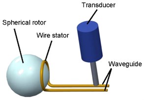
The imaginal diagram of micro spherical ultrasonic motor is shown in Fig. 1. The schematic diagram of micro ultrasonic motor is shown in Fig. 2. When vibration is applied at waveguide of wire stators, traveling wave is generated and spherical rotor is driven.
Fig. 1Imaginal diagram of micro spherical ultrasonic motor

Fig. 2Schematic diagram of micro ultrasonic motor
2. Single spiral type of wire stator spherical ultrasonic motor
The authors have made spiral wire stators as shown in Fig. 3. The authors have made two kinds of wire stators; single and multiple spiral wire stators. The specification of each stator is shown in Table 1. In the previous research, the authors have used multiple spiral wire stators with a pair of right and left spiral ones because of torque’s first priority. However, the contact area between the multiple spiral wire stators and the spherical rotor is small and irregular because of machining error. Therefore, the authors have used single spiral wire stators due to the stable rotation. In order to prevent mutual contact between the two stators for 2-axis drive, the outside diameter of spiral is 10.0 mm.
The authors have made two degree-of-freedom spherical ultrasonic motor using single spiral wire stators as shown in Fig. 4. It has two sets of wire stators orthogonal each other. It is controlled by applied voltage.
Fig. 3Wire stators
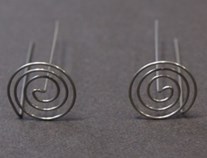
a) Multiple spiral
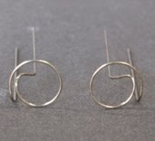
b) Single spiral
Table 1Specification of each stator
Number of spirals | 3 | 1 |
Outside diameter of spiral [mm] | 12 | 10 |
Length of wave guide [mm] | 30 | |
Wire diameter [mm] | 0.5 | |
Material | SUS304 | |
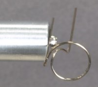
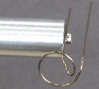
There are two ways of traveling wave direction; traveling from outside to the center and traveling from the center to outside. In this paper, the authors call the former way a forward driving and the latter way a reverse driving. The forward driving and reverse driving are shown in Fig. 5.
In previous research, it has eight rotational direction as shown in Fig. 6 and Table 2.
Fig. 4Experiment equipment for 2-axis drive
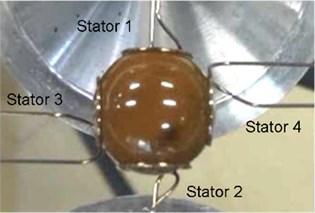
Fig. 5Connection method
a) Forward
b) Reverse
Fig. 6Rotational direction
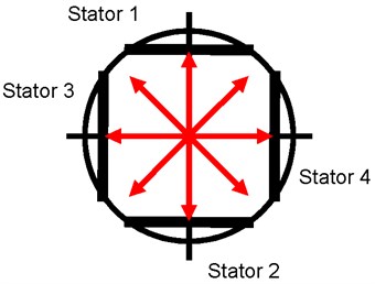
Table 2Relationship between rotational direction and output of each stator
Direction | Stator 1 & 2 | Stator 3 & 4 |
Right | Forward | Standing wave |
Upper Right | Forward | Forward |
Upper | Standing wave | Forward |
Upper Left | Reverse | Forward |
Left | Reverse | Standing wave |
Lower Left | Reverse | Reverse |
Lower | Standing wave | Reverse |
Lower Right | Forward | Reverse |
3. Precise control of rotational direction of wire stator spherical ultrasonic motor
In this research, rotational direction can be precisely controlled by duty ratio of traveling wave and standing wave.
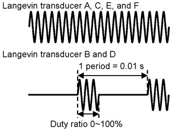
The experimental equipment of duty ratio is shown in Fig. 7. In the experiment, the authors have put a black mark on the spherical rotor using for showing the rotational direction. Six Langevin transducers are connected with four wire stators. Langevin transducers A, C, E, and F are connected to the forward driving. Langevin transducers B&D are connected to the reverse driving. The wave of each stator is shown in Fig. 8. The period of output of Langevin transducers B&D are 0.01 s, the duty of output is from 0 % to 100 %. When Langevin transducers B&D are turned OFF and Langevin transducers A, C, E, and F are turned ON, all stators generate traveling wave, the direction of the spherical rotor is upper right. When Langevin transducers B&D are turned ON, the combination of traveling wave of stators A&B and the traveling wave of stators C&D are standing wave, but stators E&F generate the traveling wave, the direction of the spherical rotor is right. When the output of Langevin transducers B&D are duty ratio, the direction of the spherical rotor is between the two directions as shown in Fig. 7. The rotational direction can be precisely controlled by duty ratio.
Fig. 7Experimental equipment of duty ratio
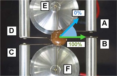
Fig. 8Wave of each stator
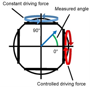
The experimental conditions are as following. The duty ratio is changed by 10 %. The applied voltage is 20 Vp-p. The applied frequency is 24.6 kHz. The defined angle of the rotational direction is shown in Fig. 10. The relationship between angle of rotational direction and duty ratio is shown in Fig. 9. The angle of rotational direction decreases with increasing the duty ratio. From the experimental results, the influence of the driving force is small, but the rotational direction can be controlled by duty ratio.
Fig. 9Relationship between angle of rotational direction and duty ratio
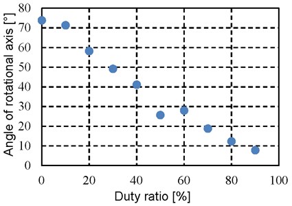
Fig. 10Rotational axis and measured angle
4. Performance evaluation of wire stator spherical ultrasonic motor
4.1. Relationship between pressing force and rotational speed
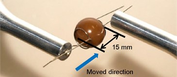
The experimental equipment of pressing force is 1-axis driving as shown in Fig. 11. The spherical rotor of diameter 15 mm is located in two wire stators. The experimental conditions are as following. Step 1, the applied frequency is 24.6 kHz, the applied voltage is 10 Vp-p. Step 2, one wire stator is pushed to move in the direction of the arrow as shown in Fig. 11, the contact point between the spherical rotor and wire stator is 0 mm as the reference point, one stator is moved from 2 mm to 4 mm by 0.1 mm, another stator is fixed and pressed, the rotational speed is measured. Step 3, the applied voltage is changed from 10 Vp-p to 70 Vp-p by 10 Vp-p, then step 2 is repeated. The pressing force is obtained from the load cell in the experiments.
Fig. 11Experimental equipment of pressing force
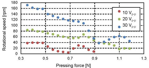
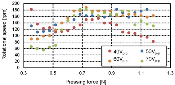
The experimental results are shown in Fig. 12 and Fig. 13.
The relationship between pressing force and rotational speed with the applied voltage changed from 10 Vp-p to 30 Vp-p is shown in Fig. 12. The rotational speed is tended to decrease as the pressing force increases and the change is small after pressing force 0.8 N. In addition, the rotational speed is increased a little before and after 0.8 N. As a cause, the wire stators are deformed as the pressing force increases, the contact position of the spherical rotor and wire stator can be shifted slightly, the direction of vibration transmission is changed.
Fig. 12Relationship between pressing force and rotational speed (10 Vp-p-30 Vp-p)
The relationship between pressing force and rotational speed with the applied voltage changed from 40 Vp-p to 70 Vp-p is shown in Fig. 13. The rotational speed is decreased in the vicinity of pressing force 0.4 N. The rotational speed is increased as the pressing force is changed from 0.5 N to 0.7 N, the rotational speed is maximum in the vicinity of 0.7 N. In addition, the relationship between amplitude of voltage and pressing force is shown. The rotational speed is increased as the amplitude of voltage decreases before 0.5 N. The relationship between rotational speed and amplitude of voltage is reversed as the pressing force is changed from 0.5 N to 0.7 N. As a cause, the vibration in the contact area between the wire stators and the spherical rotor is large in the condition of weak pressing force and high voltage. Therefore, ultrasonic vibration is considered suitable for transmission to the spherical rotor.
Fig. 13Relationship between pressing force and rotational speed (40 Vp-p-70 Vp-p)
4.2. Experiment of starting torque of wire stator spherical ultrasonic motor
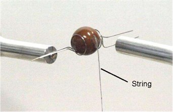
The experimental equipment of starting torque is 1-axis driving with a string as shown in Fig. 14. The spherical rotor of diameter 15 mm is located in two wire stators.
Fig. 14Experimental equipment of starting torque
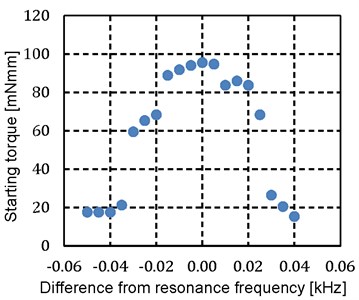
First, the applied voltage is fixed to 40 Vp-p, the starting torque is measured by changing the applied frequency. The weights are attached in the end of string, the vibration is generated to the wire stators, the spherical rotor is driven, and the operation of the spherical rotor is observed. The spherical rotor is stopped when the weights are 1000 mg. The load is reduced by 10 mg until the spherical rotor start to rotate. The above operation is repeated from the applied frequency changed by 0.005 kHz. The starting torque is maximum at frequency 24.6 kHz. The relationship between frequency and starting torque of forward rotation is shown in Fig. 15. The relationship between frequency and starting torque of reverse rotation is shown in Fig. 16.
Fig. 15Relationship between frequency and starting torque of forward rotation
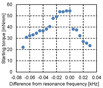
Fig. 16Relationship between frequency and starting torque of reverse rotation
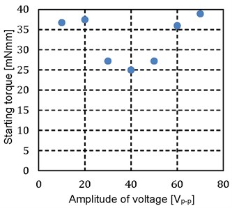
Second, the frequency is fixed to 24.6 kHz, the applied voltage is changed from 10 Vp-p to 70 Vp-p, and the starting torque is measured. The relationship between amplitude of voltage and starting torque of forward rotation is shown in Fig. 17. The relationship between amplitude of voltage and starting torque of reverse rotation is shown in Fig. 18.
The starting torque is high when the applied voltage is low. The starting torque is decreased rapidly in the vicinity of voltage 20 Vp-p of forward rotation and 30 Vp-p of reverse rotation. The cause of the phenomenon is the friction. The vibration in the contact surface of the wire stator is small at low voltage. Therefore, the static friction between the spherical rotor and wire stator is considered to cause high starting torque. The vibration in the contact area between the wire stators and the spherical rotor is large and the pressing force is low at high voltage. Therefore, the dynamic friction between the spherical rotor and wire stator is considered to cause low starting torque. The friction is changed from static friction to dynamic friction as the applied voltage increases, the driving force to the spherical rotor is reduced and the starting torque is reduced.
Fig. 17Relationship between amplitude of voltage and starting torque of forward rotation
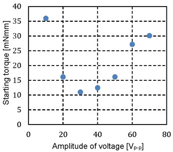
Fig. 18Relationship between amplitude of voltage and starting torque of reverse rotation
5. Conclusions
In this research, the authors have concluded as follows:
1. The authors have designed and made an ultrasonic motor using single spiral wire stators.
2. The authors have examined that the rotational direction can be controlled by duty ratio.
3. The authors have showed the drive properties of rotational speed and relationship between amplitude of voltage or frequency and starting torque.
References
-
Takesue N., et al. Position control methods of spherical ultrasonic motor. Proceedings of IEEE/RSJ International Conference on Intelligent Robots and Systems, 2010, p. 3061-3066.
-
Sashida T., Kenjo T. An Introduction to Ultrasonic Motors. Oxford University Press, Oxford, 1993.
-
Purwanto E., Toyama S. Control method of a spherical ultrasonic motor. Proceedings of IEEE/ASME International Conference on Advanced Intelligent Mechatronics, 2003, p. 1321-1326.
-
Mashimo T., Awaga K., Toyama S. Development of a spherical ultrasonic motor with an attitude sensing system using optical fibers. Proceedings of IEEE international conference on robotics and automation, 2007, p. 4466-4471.
