Abstract
Developed in the artificial intelligence community, an intelligent agent is an autonomous abstract or software entity that observes through sensors and acts upon an environment in an adaptive or intelligent manner. In a centralized control system, one central controller uses the global measurement data collected from all the sensors installed in the structure to make control decisions and to dispatch them to control devices. The centralized controller itself represents a single point of potential failure. To overcome this shortcoming, decentralized control is used to improve redundancy. This paper introduces three ideas to vibration control of smart structures: agent technology, replicator dynamics from evolutionary game theory, and energy minimization. It presents two new methods: 1) a single-agent Centralized Replicator Controller (CRC) and a decentralized Multi-Agent Replicator Controller (MARC) for vibration control of smart structures. The use of agents and a decentralized approach enhances the robustness of the entire vibration control system. The proposed control methodologies are applied to vibration control of a 3-story steel frame and a 20-story steel benchmark structure subjected to two sets of seismic loadings: historic earthquake accelerograms and artificial earthquakes and compared with the corresponding centralized and decentralized conventional Linear Quadratic Regulator (LQR) control algorithm.
1. Introduction
The concept of structural control was introduced by Yao in 1972 [1]. Since then the area has grown rapidly. Active, semi-active, and hybrid vibration control of bridge and building structures has been the subject of significant research for the past twenty-five years [2-5]. The goal is to develop a new generation of smart/adaptive structures equipped with sensors and actuators in which sensors measure the response of the structure in real time and actuators and damping devices apply the required forces to minimize the response of the structure [6, 7]. In order to accomplish this objective, various researchers have proposed an array of techniques and devices. Fisco and Adeli [8] present a review of active and semi-active vibration control of structures. Fisco and Adeli [9] present a review of hybrid control systems and control strategies. Gutierrez Soto and Adeli [10] discuss placement of control devices for passive, semi-active, and active vibration control of structures.
Developed in the artificial intelligence community, an intelligent agent is an autonomous abstract or software entity that observes through sensors and acts upon an environment in an adaptive or intelligent manner [11-13]. In the past few years agents have been used in civil and structural engineering, for example, to build a flexible structural health-monitoring sensor network [14], to model homeowners’ dynamic interactions with their neighbors following disasters [15], to model crowd behavior [16], and optimum design of a water distribution system [17].
Sustainable design of high-rise building structures is currently an active area of research [18, 19]. Energy consumption is at the core of a sustainable design [20]. For any practical implementation of active and semi-active vibration control of large structures, energy consumption must be an important consideration when selecting a control algorithm. Hence, this research advances the idea of limiting the power available to each actuator or the total available power of an emergency generator as a design parameter in the control algorithm formulation. Recently, replicator dynamics was used for temperature control in energy efficient buildings [21]. In this research, replicator dynamics is used to obtain vibration reduction while optimally allocating the available power (i.e. power generator capacity).
This paper introduces three ideas to vibration control of structures: agent technology, replicator dynamics from evolutionary game theory, and energy minimization. It presents two new methods: 1) a single-agent Centralized Replicator Controller (CRC) and a decentralized Multi-Agent Replicator Controller (MARC) for vibration control of smart structures subjected to dynamic external loading such as seismic loading. A structure is decomposed into a number of substructures with each substructure owning its own controller and set of actuators. The use of agents and a decentralized approach enhances the robustness of the entire vibration control system, as a malfunction of an individual agent can be compensated for by nearby agents. The agents make control decisions using the replicator dynamics. The proposed control methodologies are applied to vibration control of a 3-story steel shear frame and a 20-story benchmark steel building structure subjected to historical earthquake accelerograms and are compared with corresponding centralized and decentralized conventional Linear Quadratic Regulator (LQR) control algorithm.
2. Centralized versus decentralized control
2.1. General
In a centralized control system, one central controller uses the global measurement data collected from all the sensors installed in the structure (which are usually on different floors in two principal directions) to make control decisions and dispatches those decisions to control devices [22-24]. In such a system, the requirements on communication range and data transmission bandwidth increase with the size of the structure and the number of sensors and control devices deployed. These communication requirements can impose economic and technical difficulties for the implementation of feedback control systems in increasingly larger and complex civil structures such as high-rise and super high-rise building structures with thousands of members. With the increase in system dimensionality, the required centralized control computations increase exponentially [24].
The centralized controller itself represents a single point of potential failure [25]. In a centralized control system, the control gain is computed from the state measurement of the structure. To overcome the shortcomings of a centralized control system, the concept of decentralized control is proposed to replace the global control system with several local control systems. In centralized control, if the controller fails to operate, the entire control system fails to do its task. In decentralized control, if one decentralized controller fails to operate, only one part rather than the whole feedback layer fails to do its task. This will add to system reliability significantly [26]. As a result, the control problem is divided into a collection of smaller sub-systems that can be controlled on a local level by decentralized controllers. In a decentralized system, control computations can be performed in parallel [27] in a distributed computing environment of clustered workstations [28].
Although a decentralized control has its limitations since a decentralized controller makes control decisions based on localized measurements, a decentralized control system provides the following advantages [26, 29]:
a) Increased robustness and reliability against power and operational failures,
b) Reduced complexity,
c) Reduced communication,
d) Computational efficiency in a distributed computing environment in real time, and
e) Reduced energy requirements.
A brief review of decentralized control in structural engineering is presented in the next section.
2.2. Literature review on decentralized control
Kane et al. [30] use market-based decentralized control for a 6-story shear frame with semi-active magneto-rheological dampers subjected to shake table tests. Market-based control uses the theory of market supply and demand, allowing actuators to purchase from a limited resource of power. The decentralized LQG and market-based controller yielded performance on par with the displacement and acceleration reduction of the centralized controller.
Lei et al. [31] used a decentralized LQG-based control algorithm for a 20-story steel benchmark frame structure subjected to seismic loading. They subdivided the structure into 2 and 3 substructures and studied the effect of using recursive Kalman filter estimation to obtain interface measurements between substructures.
Bakule et al. [32] presented a decentralized LQG control design for a 20-story steel benchmark frame structure subjected to seismic loading by decomposing the structure into two subsystems. They concluded that decentralized control reduces the communication costs and increases the operational reliability and implementation practicality. They concluded that decentralized and centralized controllers have similar vibration control reduction and recommended the decentralized controller because of its robustness. Loh and Chang [33] also implemented LQG control strategy for several levels of decentralization. Rofooei and Monajemi-Nezhad [34] used decentralized Linear Quadratic Regulator (LQR) control for a 30-story lumped-mass example divided into different sets of substructures.
Nelson et al. [35] investigated peak strain reduction of a dynamic model representation of the Cedar Avenue tied arch steel bridge located in Minnesota using semi-active decentralized proportional controllers with velocity feedback output. They concluded that when using multiple devices for semi-active control, specific considerations should be given to the number and placement of devices according to the natural frequencies of the structure – and also to reduce power, size, and cost considerations. They also concluded that the semi-active control system was not able to perform reduction as effectively as an active control system and that four devices were not enough to mitigate the vibration of the bridge when the loads were tuned to the natural frequency.
3. Centralized structural control using replicator dynamics
3.1. Equations of motion for a controlled structure
The equations of motion for a multi-degree-of-freedom (MDOF) structure with a lumped-mass model with -degrees of freedom subjected to external excitations such as earthquake loading and controlling devices are expressed as [36]:
where is the displacement vector relative to the ground, are the mass, damping, and stiffness matrices, respectively; is the control force vector and the external excitation is the ground acceleration time history; and are the control and excitation location matrices, respectively. The spatial load pattern vector is equal to . Using Eq. (1), a state-space representation of the control problem can be written as:
where is the state vector, is the structural system matrix, is the control matrix, is the excitation matrix; is the system output and and are the state and control force transformation matrices, respectively:
3.2. Replicator dynamics
Bio-inspired computing has been the subject of significant research in recent years such as evolutionary computing and genetic algorithms [37-40], particle swarm optimization [41], ant colony optimization [43], water drop algorithms [43] and spiral dynamic algorithms [44]. In evolutionary game theory, entire groups of players are involved in a game [45]. Each player chooses a strategy from a specific set of strategies with the goal of winning the game [46]. Replicator dynamics is a bio-inspired concept that models how natural selection affects the population according to their habitat in an environment based on a measured fitness function or payoff. The number of individuals in each habitat varies as a result of the interaction and comparison with the average fitness of the total population. Replicator dynamics can be interpreted economically as a model of imitation of successful individuals [47]. Recently, replicator dynamics was used to solve resource allocation problems in engineering, for example, for temperature control in energy efficient buildings [21], for electrical power grid distribution [48], and for water distribution control [49].
Suppose a set players are participating in an evolutionary game and competing for total available resources, . Each player, , uses resources, in order to play the game:
The amount of resources needed for a player to win the game (get closer to the goal) is determined by the fitness function (payoff) of each player, , and how it compares with the fitness function of other players in the game (weighted average), . The goal can be either achieving the smallest or the largest payoff. The former is used in this research that is to have the smallest displacement/drift/acceleration given the available resources. This dynamic is known in behavioral ecology as replicator dynamics and is defined by the following differential equation [37]:
where the weighted average fitness is the average payoff in the population at time defined as:
If a player, , has a higher payoff when compared with the weighted average , it will need more resources, , from the total available resources, . On the other hand, when a player’s payoff is smaller than the weighted average, , it will require less resources to achieve the goal and thus the resource at the time , , will decrease in size.
This concept is adapted for the structural control problem. Let be the total number of control devices (the same as the number of players in the game theory). The sum of the control forces of the entire control system is , which is related to the total power required to actuate the system, which in turn can be taken as the capacity of the emergency power generator in the case of an extreme dynamic event such as a seismic event. Each player (control device) has a maximum amount of resources that can use in the game, which is the maximum capacity of the control device.
Following Obando et al. [21] who used replicator dynamics to solve the temperature control problem in a building with 4 rooms set at different temperature points, Eq. (6) of the replicator dynamics is modified as follows:
where is a strictly positive parameter that regulates the population growth rate. The growth rate parameter relates to control problem as the reaction speed of the actuator: the higher the growth rate, the faster the reaction time required by the actuator.
3.3. Fitness function
The fitness function is a strictly positive ( value in the replicator dynamics concept. The fitness function proposed by Obando et al. [38], , assumes that the input, in their case temperature, , and in the current research displacement , remains positive. However, because the displacement of a structure can have negative values requiring the actuator force to act in the opposite direction, a new fitness function is formulated in this research as the maximum of the desired displacement (zero or close to zero) and the current displacement of the th floor:
where is the desired displacement for the th floor. The fitness function is therefore strictly positive ( and is calculated so that it takes into account the current structural displacement , compares it with the desired displacement , and generates the force required by the th actuator to attain the control objective, for example, minimizing drift or the total control force requirement. The desired displacement parameter for the th floor is selected considering performance level, damage state, and inter-story drifts.
In order to investigate the performance improvement other fitness function strategies are investigated using velocity and acceleration feedback. Similar to Eq. (9), the fitness function for acceleration feedback is as follows:
where is the desired velocity for the th floor, meaning the rate of change to make a decision in one direction or the other. In practice, selection of measured displacement, velocity, or acceleration responses as feedback strategy is based on the availability of measuring sensor types.
The control force direction is determined as follows. There are two control replicators, one for positive state measurements and the other for negative state measurements. When the measured displacement at a specific time is positive, for example, the force from the first replicator will be positive and from the second replicator will be zero. When the subtraction of the positive replicator from the negative replicator is negative, the resulting force for that particular actuator, , will be negative which means the force is applied in the direction opposite to the direction of motion.
3.4. Power limitation
Obando et al. [21] introduced a fictitious room with a desired temperature in the replicator dynamic derivation to reduce the power requirement. In the temperature control problem, the configuration is centralized. A similar concept is employed but adjusted to the structural control problem by adding a fictitious floor. Eq. (5) is transformed to:
where the control force allocated to the fictitious floor is:
Therefore, the sum of the actual control forces allocated to actuators is less than the total sum of control forces including the fictitious control force:
The fitness for the fictitious zone is determined a priori which influences the replicator dynamics to achieve the control objective. The fitness function of the fictitious floor is chosen to be close to the desired displacement (). Based on this selection if the displacement of a floor is greater than its desired displacement, , its corresponding fitness function is greater than and thus, the player (actuator) on the th floor requires more resources (control forces). On the other hand, if the fitness of a floor is smaller than then the remaining excess of resources are attracted to the fictitious actuator, which means that the excess of resources (power supply to the actuator) is not used and the energy consumption of the control system is minimized.
4. Multi-agent decentralized structural control using replicator dynamics
4.1. Decentralized control equations
A decentralized control algorithm requires a substructuring scheme [31-34]. Following Lei et al. [31] a large structure is divided into a set of substructures, and forces at the interfaces between the substructures are treated as external disturbances on each substructure. The equation of motion of the th substructure derived from Eq. (1) is:
Subscript represents the internal DOF in the substructure while subscript makes reference to the interface DOF. The interaction between the interfaces can be derived as external disturbances to the substructure as:
where is the transformation vector of the interface force vector Similarly, following Eqs. (2-3), the state space equation of substructure is:
4.2. Multi-agent replicator dynamics
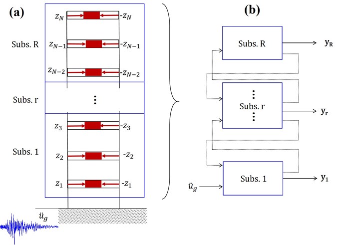
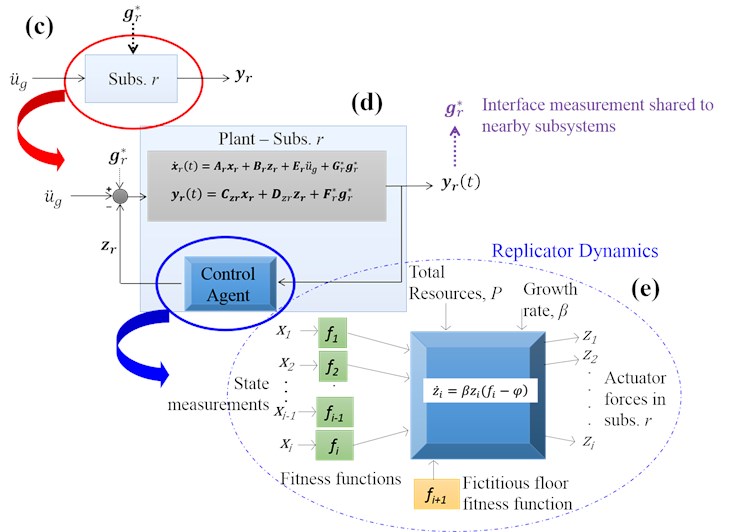
A Multi-Agent Replicator Control (MARC) methodology is developed for vibration control of smart structures through the integration of decentralized control, replicator dynamics and agent modeling in structural control of buildings subjected to dynamic loads shown schematically in Fig. 1. Figs. 1(a) and 1(b) show a large structure divided into a set of substructures, and forces at the interfaces between the substructures are treated as external disturbances on each substructure [31]. In a multi-agent system when the structure is subdivided into subsystems (Fig. 1(d)), each subsystem has its own controller modeled as an agent (Fig. 1(c)) that makes control decisions in real time based on the locally sensed information. The decision of each agent, however, affects other agents because they are all interconnected by the dynamics of the system. Agents change information only with adjacent agents. Control agents distribute resources in a decentralized control environment to specific control devices to achieve vibration control that is to minimize floor accelerations and lateral displacements using the principles of the replicator dynamics (Fig. 1(e)). The consensus law is based on the replicator dynamics presented by Eq. (6).
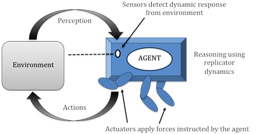
Both centralized and decentralized replicator controllers are investigated in this paper. Fig. 2 presents an agent representation for autonomous control of smart structures. A single agent, in this case, can be interpreted as a centralized replicator controller when one control agent makes the decisions in real time for the entire structure. It can also be interpreted as one of the control agents that are making the decisions based on localized information of its substructure and the information from the other substructures.
The power limitation for the replicator dynamic controller explained in the previous section is implemented in the following manner depending on the centralized or decentralized configuration. A centralized replicator controller has one fictitious floor while the decentralized replicator controller has one fictitious floor per substructure. In other words, an additional fictitious floor per substructure with a fictitious actuator is introduced in the replicator dynamic algorithm. Displacement, velocity, or acceleration feedback is used to define fitness functions for both MARC and CRC.
5. Linear quadratic regulator
In LQR, control forces are found by minimizing a quadratic cost function, , in the following form:
where is a symmetric positive semi-definite matrix and is a symmetric positive definite matrix determined by the control designer. Defining places the controlled output in the cost function and is the identity matrix. is the control gain defined as , where is the symmetric positive semi-definite solution of the algebraic Riccati equation [50]:
Fig. 1Integration of decentralized control, replicator dynamics and agent modeling in structural control of buildings subjected to dynamic loads
For the decentralized configuration, the gain matrix is calculated using the substructure properties. In that case, the function is minimized using the matrices and defined by Eq. (16) instead of and and similarly matrices and are defined according to the measurements, and actuators for that particular substructure. In this research, the centralized LQR (CLQR), and the decentralized LQR (DLQR) are computed using displacement and velocity measurements of all floors. In order to obtain the full-state displacement feedback, the top halves of and , are the identity matrix. Note that for DLQR, the interface measurements are not included in the calculation of the gain matrix, . Multiple controllers are designed independently. In DLQR and the proposed MARC, the proposed decentralized control approach differs from previous research in decentralized control. The matrix is not truncated because of the sub-system approach with communication between sub-systems at the interface floor levels.
Fig. 2Agent representation for autonomous control of structures
6. Application
6.1. Example 1
The example is a two-dimensional three-story lumped-mass shear frame structure taken from the literature [51] as a proof of concept example with the following properties:
The new methodologies, CRC and MARC, are applied to a shear frame benchmark problem subjected to near and far field historical records of four large earthquakes: (a) the N-S component of the El Centro, California, far field earthquake (Peak Ground Acceleration = PGA = 0.348 g) recorded at the Imperial Valley on May 18, 1940, (b) the N-S component of Hachinohe, Japan, far field earthquake (PGA = 0.229 g) recorded on May 16, 1968, (c) the N-S component near field Kobe earthquake (PGA = 0.59 g) recorded at Hyogo-ken Nanbu on January 28, 1995, (d) the N-S component of near field Northridge (PGA = 0.843 g) earthquake recorded in Sylmar, California on January 17, 1994. The time histories of these records are displayed in Fig. 3. The PGA in each case is noted in the figure in terms of the gravity acceleration.
A systematic evaluation of the control strategy performance is performed employing 8 of the 16 revised evaluation criteria used in Bakule et al. [32] and included in the Appendix. The quality of a control strategy is based on those criteria defined in terms of maximum response quantities as well as the number of sensors and control devices and the total power required. The decentralized control system for MARC is fully decentralized, meaning each floor is a subsystem. The second floor shares full state measurement information with the top and bottom floors. The vibration reduction performance of CRC and MARC depends on the magnitude of , the sum of the maximum of all control forces (their capacities) available, the population growth rate , and the value of the fitness function of the fictitious floor. The latter two also affect the stability of the control algorithm. The value of is chosen based on the availability and costs of the actuators. Proper values of in the range 0.01-300 and the fitness function value of the fictitious floor are determined based on a sensitivity analysis.
Fig. 3Time history earthquake accelerogram records: a) El Centro (May 18, 1940, M= 7.1), b) Hachinohe (May 16, 1968, M= 8.0), c) Kobe (January 28, 1995, M= 6.9), d) Northridge (January 17, 1994, M = 6.7)


Fig. 4Sensitivity analyses of the maximum displacement of the structure in terms of the growth rate of the population and total sum of actuator forces for CRC using four different historical earthquake accelerograms
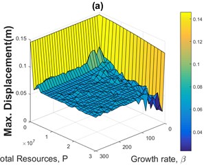
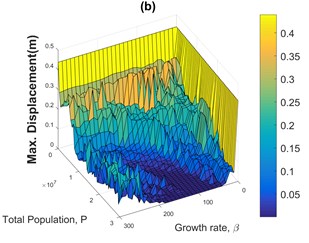
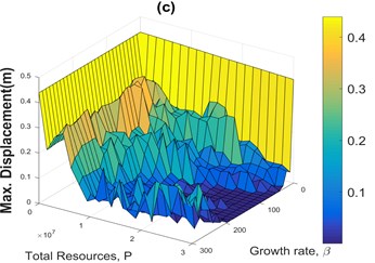
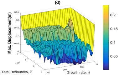
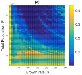
Figs. 4(a) to 4(d) are pictorial representations of the sensitivity analyses of the maximum displacement of the structure in terms of the growth rate coefficient and the total sum of actuator forces (population size) for the CRC using four different accelerograms. Fig. 4(e) is a flat representation of Fig. 4(b) included as a sample. Fig. 4 and similar figures are used to find proper values for the growth rate , and the value of the fitness function of the fictitious floor based on maximum vibration reduction and minimum energy consumption.
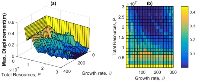
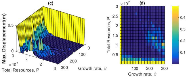
Fig. 5 presents the sensitivity analysis of CRC for maximum displacement (5(a), 5(b)), maximum floor acceleration of the structure (5(c), 5(d)), and maximum actuator force (5(e), 5(f)) versus the growth rate of the population and the total sum of actuator forces for the 3-story example subjected to Kobe near field historical earthquake. Fig. 6 presents a comparison of the sensitivity analyses of the maximum displacement of the structure in terms of the growth rate of the population and total sum of actuator forces (population size) for both CRC and MARC using Kobe accelerogram. It is observed that MARC requires a smaller population growth rate and population size than CRC to accomplish similar vibration reduction which means a) reduced actuator capacity requirement and cost and b) less energy demand.
Fig. 5Sensitivity analysis of CRC for a) and b) maximum displacement and c) and d) maximum floor acceleration of the structure, and e) and f) maximum actuator force versus the growth rate of the population and total sum of actuator forces for the 3-story example subjected to Kobe near field historical earthquake
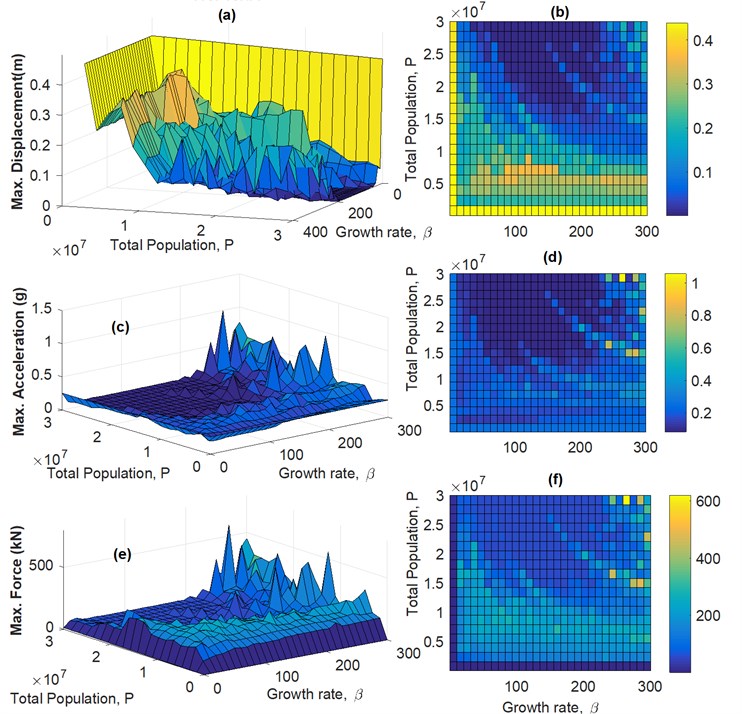
Based on extensive sensitivity analyses, a sample of which is presented in Figs. 4-6, the best results in terms of both vibration reduction and energy consumption for CRC and MARC are determined. The performance of the proposed algorithms, CRC and MARC, is compared with two versions of the LQR algorithm, CLQR and DLQR. For the 3-story example, the control force time-histories for all four control algorithms are similar when subjected to far field Hachinohe earthquake (case 1). In the first case, the maximum control efforts are made similar for all four control algorithms. This is achieved by choosing the following parameters for LQR: ) and using full-state displacement measurements. CRC replicator parameters are 103.5 with 23,600 kN and 0.0001 m/sec for the velocity fitness function of the fictitious floor. For MARC the best results are obtained for 93.11 with 4,730 kN and 0.0001 m/sec for the velocity fitness function of the fictitious floor. The results for CRC, MARC, the centralized LQR (CLQR), and the decentralized LQR (DLQR) subjected to far field Hachinohe earthquake are shown in Fig. 7 for maximum displacement and maximum actuator force and Fig. 8 for maximum acceleration. In this case, the maximum actuator control forces from all control algorithms shown in Fig. 7(c) are similar as expected and vibration reduction performances of different methods are evaluated. CLQR, DLQR, CRC, and MARC control algorithms use a maximum control force of 16.1 kN, 23.4 kN, 14.13 kN and 15.2 kN, respectively. CLQR, DLQR, CRC, and MARC control algorithms reduce the maximum displacement by 98.6 %, 97.5 %, 99.9 %, and 99.8 %, respectively, the maximum acceleration by 85.8 %, 55.3 %, 86.4 % and 88.1 %, respectively, and maximum inter-story drift by 98.2 %, 96.8 %, 99.9 % and 99.8 %, respectively. Fig. 9(a) and 9(b) show the maximum inter-story drifts for CRC, MARC, CLQR, and DLQR subjected to far field Hachinohe and near field Kobe earthquakes, respectively.
Fig. 6Sensitivity analysis of maximum displacement of the structure versus the growth rate of the population and total sum of actuator forces for the 3-story example subjected to Kobe near field historical earthquake: a), b) CRC and c), d) MARC
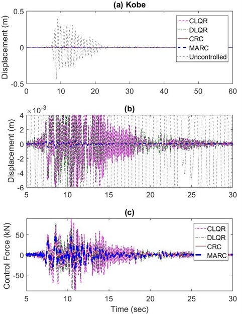
Using the same sets of values obtained for the parameters of the replicator dynamics based on sensitivity analysis the structure is subjected to near field Kobe earthquake (case 2) the algorithms are compared based on the performance criteria. The results for maximum floor displacements and accelerations for the near field Kobe earthquake are shown in Figs. 10 and 11, respectively. CLQR, DLQR, CRC, and MARC control algorithms use a maximum control force of 88.1 kN, 92.2 kN, 49.61 kN and 51.7 kN, respectively. CLQR, DLQR, CRC, and MARC algorithms reduce the maximum displacement by 97.9 %, 97.2 %, 99.9 %, and 99.9 %, respectively, maximum acceleration by 55.4 %, 37.9 %, 88.0 % and 85.3 %, respectively, and maximum inter-story drift by 97.4 %, 96.4 %, 99.9 % and 99.8 %, respectively. It was found that the proposed control algorithms were able to provide a better vibration reduction compared with the LQR control algorithms using less control effort.
Fig. 7a) Maximum roof displacement results for CRC, MARC, CLQR, and DLQR subjected to far field Hachinohe earthquake, b) The 5-30 seconds range expanded, c) Maximum actuator force (kN) along the 5-30 seconds range expanded
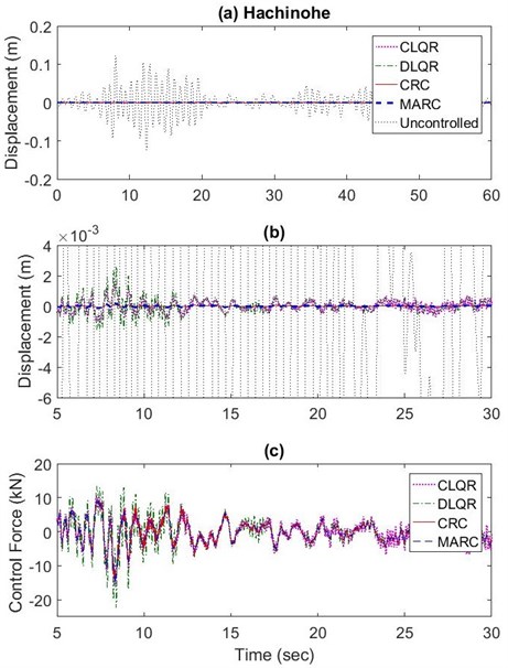
Fig. 8a) Maximum roof acceleration results for CRC, MARC, CLQR, and DLQR subjected to far field Hachinohe earthquake b) 2-19 second range
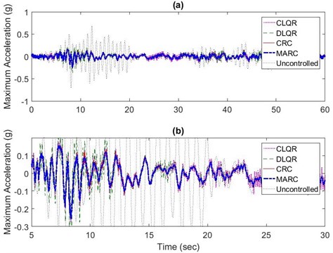
Fig. 9Maximum relative displacement for CRC, MARC, CLQR, and DLQR subjected to: a) far field Hachinohe earthquake and b) near field Kobe earthquake
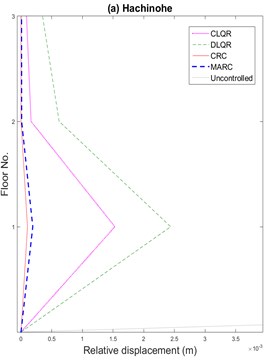
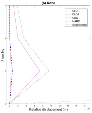
Fig. 10a) Maximum roof displacement results for CRC, MARC, CLQR, and DLQR subjected to near field Kobe earthquake, b) The 5-30 seconds range expanded, c) maximum actuator force (5-30 sec expansion)
The new control algorithms, CRC and MARC, are also evaluated and compared with CLQR and DLQR algorithms using the performance criteria summarized in Appendix. The results are presented in Table 1 for far field Hachinohe and near field Kobe earthquakes. The smaller the value in the table, the better the performance. MARC provided the best performance for far-field earthquake according to the performance criteria in terms of maximum floor acceleration and base shear. CRC and MARC overall provided better performance compared to CLQR and DLQR in terms of maximum displacement, inter-story drift, actuator stroke (maximum inter-story drift, and actuator stroke (the length of working movement done by the actuator an operational variable that is critical for selection of the actuator), instantaneous power and maximum power for the control system. Overall, CRC and MARC methodologies provided better performance while using minimum power and the same number of control devices.
Fig. 11a) Maximum absolute roof acceleration results for CRC, MARC, CLQR, and DLQR subjected to near field Kobe earthquake, b) The 5-20 second range
Table 1Performance criteria evaluation of 3-story example for CLQR, DLQR, CRC and MARC when subjected to far field Hachinohe earthquake and near-field Kobe earthquake
Performance criteria | Far-field Hachinohe earthquake | Near-field Kobe earthquake | ||||||
CLQR | DLQR | CRC | MARC | CLQR | DLQR | CRC | MARC | |
0.0133 | 0.0249 | 0.0011 | 0.0016 | 0.0202 | 0.0280 | 0.0008 | 0.0014 | |
0.0266 | 0.0432 | 0.0023 | 0.0035 | 0.0367 | 0.0468 | 0.0018 | 0.0033 | |
0.3897 | 0.5702 | 0.3507 | 0.3589 | 0.5845 | 0.6389 | 0.3276 | 0.3450 | |
0.5200 | 0.7157 | 0.4610 | 0.4894 | 0.7772 | 0.8005 | 0.4675 | 0.4922 | |
0.0108 | 0.0175 | 0.0009 | 0.0010 | 0.0165 | 0.0195 | 0.0006 | 0.0008 | |
0.0206 | 0.0300 | 0.0020 | 0.0022 | 0.0269 | 0.0323 | 0.0013 | 0.0018 | |
0.3265 | 0.4126 | 0.2659 | 0.2635 | 0.4915 | 0.4574 | 0.2268 | 0.2266 | |
0.0916 | 0.1263 | 0.0802 | 0.0856 | 0.4987 | 0.4991 | 0.2813 | 0.2972 | |
6.2. Example 2
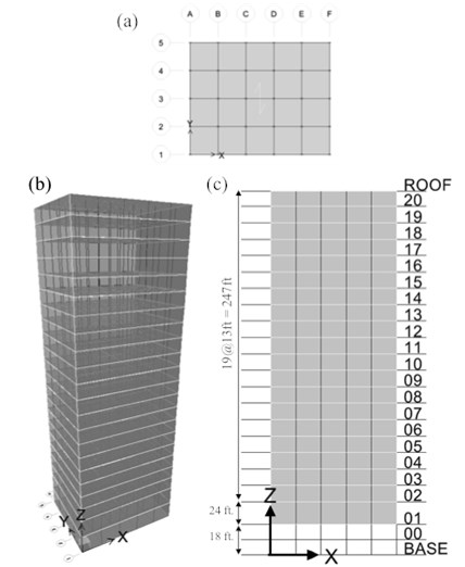
This is a steel space moment-resisting frame (MRF) benchmark structure subjected to the four earthquake accelerograms shown in Fig. 5 and artificial earthquakes. The 20-story steel structure designed by Brandow & Johnston Associates for the SAC Phase II Steel project for the Los Angeles, California, seismic region [52] is shown in Fig. 12. The columns are made of 50 ksi steel wide-flange shapes. The beams are 36 ksi steel wide-flange shapes. Floors are composite consisting of concrete and steel and modeled as a rigid diaphragm. For seismic mass determination, the following are included: steel framing, floor slabs, partitions, ceiling, flooring, mechanical, electrical, roofing and a penthouse located on the top. There are column splices every three floors designed to carry the uplifting seismic forces. The column bases are pinned at the ground level. The seismic mass of the entire structure above ground is 9.00×10⁶ kg. In the benchmark problem, the structure is modeled as a 2D MRF according to the parameters provided in Lei et al. [31]. The large structure is divided into two substructures with each substructure having 10 actuators and sensors.
The structure is subjected to artificial earthquakes using the Kanai-Tajimi equation [53, 54]:
where and are the characteristic ground frequency and damping ratio, respectively. is the amplitude. By proper selection of and the model allows adjusting the parameters to achieve various earthquake magnitude, ground frequency, and attenuation of seismic waves in the ground. Hoang et al. [55] showed the Kanai-Tajimi spectrum is comparable with the frequency content of historical seismic events such as El Centro ( 12, 0. 6) and Kobe ( 12 and 0.3). In this research, a range of ground frequencies and damping ratios were studied to determine their impact on the performance of the new control algorithms.
Fig. 12Benchmark 20-story steel structure: a) X-Y plan view, b) perspective view, c) X-Z elevation view
Replicator dynamics with acceleration or velocity feedback fitness functions were investigated. Similar to Example 1, a sensitivity analysis was performed for values of in the range 0.01-10 with each semi-active actuator maximum capacity in the range 1,000-2,500 kN and fictitious actuator fitness of 0.0001 m/sec.
Based on the simulation of 100 different artificial earthquakes per ground frequency, the results of the confidence range for the best growth rate parameter resulting in minimum floor displacements for MARC using the acceleration feedback fitness are presented in Fig. 13 (the results using the velocity feedback fitness function and for minimum floor accelerations and also for CRC are not shown due to space limitation). It is observed that the mean value for the growth rate is at 0.573 for MARC when using acceleration feedback.
The performances of MARC and CRC are compared with those of CLQR and DLQR algorithm. The parameters chosen for LQR are ) and = identity matrix using full-state measurements (both displacement and velocity). The parameters for CRC are 1.5×10⁹ and 0.26 and MARC are 1.5×10⁹ and 0.57. Sample results for maximum actuator force, maximum roof displacement, and maximum roof accelerations are presented in Fig. 14 and maximum drift in Fig. 15 using Kanai-Tajimi artificial earthquake parameters of 3, 0.34 and 1.
Fig. 13Confidence range of best growth rate parameter, β, per 100 earthquakes for So= 5 and ξg= 0.34 with changing ground frequency value, ωg, for MARC using acceleration feedback
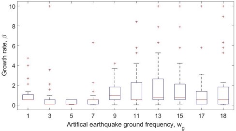
Fig. 14Time-history of a) Top-floor actuator force, b) maximum roof displacement, and c) absolute roof acceleration for 20-story benchmark building subjected to artificial earthquake accelerogram (So= 1, ξg= 0.34 and ωg= 3)
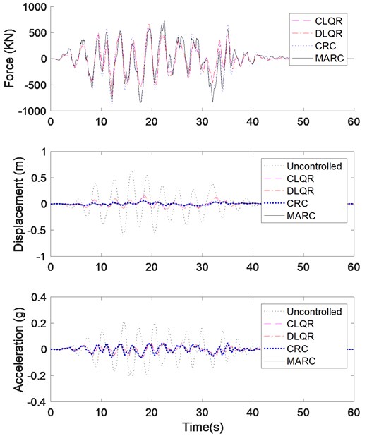
The magnitude of the maximum control forces (Fig. 14(a)) for different algorithms does not vary greatly as expected. The performance for roof accelerations (Fig. 14(c)) measurements is very approximate between all control algorithms. However, there are significant differences for maximum roof displacements shown in Fig. 14(b), and drift shown in Fig. 15. In terms of inter-story drift and displacement, MARC presents the best solution. MARC’s performance for the drift at the interface of substructures can be improved by increasing the number of substructures. One solution to improve the performance is to add a state observer to estimate the measurement of the internal states of the structure, in particular, to estimate the interface measurements. The performance criteria for the 20-story structure are summarized in Table 2. MARC shows the best overall performance. It was observed during the simulation that all the resources tend to move towards the top floors. This occurs because of the definition of the fitness function of the replicator dynamics. It is found that the best growth rate value increases with an increase in the magnitude of the earthquake.
Fig. 15Inter-story drift for 20-story benchmark structure subjected to Kanai-Tajimi artificial earthquake accelerogram (So= 1, ξg= 0.34 and ωg= 3)
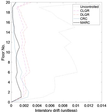
Table 2Performance criteria evaluation of 20-story example for CLQR, DLQR, CRC and MARC when subjected to Kanai-Tajimi artificial earthquake accelerogram (So= 1, ξg= 0.34 and ωg= 3)
Performance criteria | Artificial accelerogram1, 0.34 and 3) | |||
CLQR | DLQR | CRC | MARC | |
0.2678 | 0.3080 | 0.1971 | 0.1918 | |
0.2681 | 0.3089 | 0.2652 | 0.1858 | |
0.3295 | 0.3525 | 0.3454 | 0.3056 | |
0.5831 | 0.5739 | 0.6302 | 0.5728 | |
0.2359 | 0.2771 | 0.1633 | 0.1627 | |
0.2289 | 0.2701 | 0.2389 | 0.1516 | |
0.2999 | 0.3204 | 0.3115 | 0.2599 | |
7. Conclusions
An intelligent control methodology is presented for vibration reduction of structures. The concepts of agent-based modeling, replicator dynamics, and decentralized control are fused to provide a robust controller. The effectiveness of the methodology was demonstrated by applying to 3-story and 20-story frame examples. For the LQR and many other control algorithms, the goal is to determine the control gain to be used as input in the feedback control loop. This gain is determined a priori according to the structural properties and is known to be sensitive to parameter uncertainties. The methodologies presented in this research use the measured control states to allocate the forces in real time to obtain improved performance. The 3-story example provides an insight and a proof of the concept to the proposed methodology. The 20-story example verifies how communication between agents in a decentralized configuration improves the reliability of the overall control system.
The subject of control stability is of concern for its practical implementation. Wang and Adeli [56] present methods for reducing the chattering phenomenon in sliding mode control. Unlike the LQR controller, the proposed methodology has not been derived from a mathematically stable closed form. Further investigation is needed to consider the stability of the proposed algorithm using the passivity theory. On the other hand, since energy minimization is an outcome of the proposed algorithm it can be used for semi-active control of structures employing the energy of a battery. Semi-active control systems are considered Bounded-Input Bounded-Output stable [57]. The performance of the controller using replicator dynamics changes according to the total population (total sum of actuators forces for control), , and the growth rate, and the value of the fictitious floor fitness function, . In this research, a sensitivity analysis was performed to determine the appropriate values for the growth rate, population size, and power available.
The next step in this research is to integrate MARC with a multi-objective optimization algorithm in order to find Pareto optimal values for the three parameters , , and to achieve maximum structural performance with minimum energy consumption. In addition, only one value for growth rate was used for all the habitats. Further research is recommended to study growth rate for each habitat individually and how each growth rate influences the entire replicator dynamics. Application to large bridge and high-rise building structures and evaluation of parameter uncertainties and actuator/sensor failures will be another extension of the current research.
References
-
Yao J. T. P. Concept of structural control. Journal of the Structural Division, ASCE, Vol. 98, Issue 7, 1972, p. 1567-1574.
-
Adeli H., Kim H., Wavelet-Based Vibration Control of Smart Buildings and Bridges. CRC Press, Taylor & Francis, Boca Raton, Florida, 2009.
-
Amini F., Zabihi-Samani M. A Wavelet-based adaptive pole assignment method for structural control. Computer-Aided Civil and Infrastructure Engineering, Vol. 29, Issue 6, 2014, p. 464-477.
-
Andersson,A., O’Connor A.J., Karoumi R. Passive and adaptive damping systems for vibration mitigation and increased fatigue service life of a tied arch railway bridge. Computer-Aided Civil and Infrastructure Engineering, Vol. 30, Issue 9, 2015, p. 748-757.
-
Zhang M., Zhang W., Sun B., Pei Y. Multiresolution streamline placement based on control grids. Integrated Computer-Aided Engineering, Vol. 21, Issue 1, 2014, p. 47-57.
-
Adeli H., Saleh A. Control, Optimization, and Smart Structures – High-Performance Bridges and Buildings of the Future. John Wiley and Sons, New York, 1999.
-
Adeli H., Jiang X. Intelligent Infrastructure – Neural Networks, Wavelets, and Chaos Theory for Intelligent Transportation Systems and Smart Structures. CRC Press, Taylor & Francis, Boca Raton, Florida, 2009.
-
Fisco N. R., Adeli H. Smart structures: part I – active and semi-active control. Scientia Iranica – Transaction A: Civil Engineering, Vol. 18, Issue 3, 2011, p. 275-284.
-
Fisco N. R., Adeli H. Smart structures: part II – hybrid control systems and control strategies. Scientia Iranica – Transaction A: Civil Engineering, Vol. 18, Issue 3, 2011, p. 285-295.
-
Gutierrez Soto M., Adeli H. Placement of control devices for passive, semi-active, and active, vibration control of structures. Scientia Iranica – Transaction A: Civil Engineering, Vol. 20, Issue 6, 2013, p. 1567-1578.
-
Pinto T., Vale Z., Sousa T. M., Praça I., Santos G., Morais H. Adaptive learning in agents behaviour: a framework for electricity markets simulation. Integrated Computer-Aided Engineering, Vol. 21, Issue 4, 2014, p. 399-415.
-
Lin Y., Descamps P., Gaud N., Hilaire V., Koukam A. Multi-agent system for intelligent scrum project management. Integrated Computer-Aided Engineering, Vol. 22, Issue 3, 2015, p. 281-296.
-
Forero Mendoza L., Vellasco M., Figueiredo K. Intelligent multiagent coordination based on reinforcement hierarchical neuro-fuzzy models. International Journal of Neural Systems, Vol. 24, Issue 8, 2014, p. 1450031.
-
Chen B., Liu W. Mobile agent computing paradigm for building a flexible structural health monitoring sensor network. Computer-Aided Civil and Infrastructure Engineering, Vol. 25, Issue 7, 2010, p. 504-516.
-
Nejat A., Damnjanovic I. Agent-based modeling of behavioral housing recovery following disasters. Computer-Aided Civil and Infrastructure Engineering, Vol. 27, Issue 10, 2012, p. 748-763.
-
Sun Q., Wu S. A configurable agent-based crowd model with generic behavior effect representation mechanism. Computer-Aided Civil and Infrastructure Engineering, Vol. 29, Issue 7, 2014, p. 531-545.
-
Montalvo I., Izquierdo J., Herrera M., Pérez-García R. Water distribution system computer-aided design by agent swarm optimization. Computer-Aided Civil and Infrastructure Engineering, Vol. 29, Issue 6, 2014, p. 433-448.
-
Wang N., Adeli H. Sustainable building design. Journal of Civil Engineering and Management, Vol. 20, Issue 1, 2014, p. 1-10.
-
Rafiei M. H., Adeli H. Sustainability in highrise building design and construction. The Structural Design of Tall and Special Buildings, Vol. 25, Issue 13, 2016, p. 643-658.
-
Katsigarakis K., Kontes G. D., Giannakis G. I., Rovas D. V. Sense-think-act methodology for intelligent building energy management. Computer-Aided Civil and Infrastructure Engineering, Vol. 31, Issue 1, 2016, p. 50-64.
-
Obando G., Pantoja A., Quijano N. Building temperature control based on population dynamics. IEEE Transactions on Control Systems Technology, Vol. 22, Issue 1, 2014, p. 404-412.
-
Li Y., Liu C., Gao J. X., Shen W. An integrated feature-based dynamic control system for on-line machining, inspection and monitoring. Integrated Computer-Aided Engineering, Vol. 22, Issue 2, 2015, p. 187-200.
-
Guzman C., Castejon P., Onaindia E., Frank J. Reactive execution for solving plan failures in planning control applications. Integrated Computer-Aided Engineering, Vol. 22, Issue 4, 2015, p. 343-360.
-
Donnarumma F., Prevete R., Chersi F., Pezzulo G. A programmer-interpreter neural network architecture for prefrontal cognitive control. International Journal of Neural Systems, Vol. 25, Issue 6, 2015, p. 1550017.
-
Lynch J. P., Law K. H. Market-based control of linear structural systems. Earthquake Engineering and Structural Dynamics, Vol. 31, 2002, p. 1855-1877.
-
Lunze J. Feedback Control of Large-Scale Systems. Prentice Hall International, Salisbury, England, 1992.
-
Adeli H., Kamal O. Parallel Processing in Structural Engineering. Elsevier Applied Science, London, 1993.
-
Adeli H., Kumar S. Distributed Computer-Aided Engineering for Analysis, Design, and Visualization. CRC Press, Boca Raton, 1999.
-
Nekoukar V., Erfanian A. A decentralized modular control framework for robust control of FES-activated walker-assisted paraplegic walking using terminal sliding mode and fuzzy logic control. IEEE Transactions on Biomedical Engineering, Vol. 59, 10, p. 2818-2827.
-
Kane M., Lynch J. P., Law K. Market-based control of shear structures utilizing magnetorheological dampers. American Control Conference, San Francisco, CA, 2011.
-
Lei Y., Wu D. T., Lin Y. Decentralized control algorithm for large-scale building structures. Computer-Aided Civil and Infrastructure Engineering, Vol. 27, Issue 1, 2012, p. 2-13.
-
Bakule L., Papik M., Rehak B. Decentralized stabilization of large-scale civil structures. 19th World Congress, The International Federation of Automatic Control, Cape Town, South Africa, 2014.
-
Loh C-H., Chang C-M. Application of centralized and decentralized control to building structure: analytical study. Journal of Engineering Mechanics, ASCE, Vol. 13, Issue 11, 2008, p. 970-982.
-
Rofooei F. R., Monajemi-Nezhad S. Decentralized control of tall buildings. The Structural Design of Tall and Special Buildings, Vol. 15, 2006, p. 153-170.
-
Nelson G., Rajamani R., Gastineau A., Wojtkiewicz S., Schultz A. Bridge life extension using semiactive vibration control. IEEE/ASME Transactions on Mechatronics, Vol. 20, Issue 1, 2015, p. 207-216.
-
Adeli H., Gere J., Weaver W. Jr. Algorithms for nonlinear structural dynamics. Journal of Structural Division, ASCE, Vol. 104, Issue 2, 1978, p. 263-280.
-
Bolourchi A., Masri S. F., Aldraihem O. J. Studies into computational intelligence and evolutionary approaches for model-free identification of hysteretic systems. Computer-Aided Civil and Infrastructure Engineering, Vol. 30, Issue 5, 2015, p. 330-346.
-
Cheng J., Zhang G., Caraffini F., Neri F. Multicriteria adaptive differential evolution for global numerical optimization. Integrated Computer-Aided Engineering, Vol. 22, Issue 2, 2015, p. 103-117.
-
Lee H. G., Yi C. Y., Lee D. E., Arditi D. An advanced stochastic time-cost tradeoff analysis based on a CPM-guided multi-objective genetic algorithm. Computer-Aided Civil and Infrastructure Engineering, Vol. 30, Issue 10, 2015, p. 824-842.
-
Park K., Oh B. K., Park H. S. GA-based multi-objective optimization algorithm for retrofit design on a multi-core PC cluster. Computer-Aided Civil and Infrastructure Engineering, Vol. 30, Issue 12, 2015, p. 965-980.
-
Shabbir F., Omenzetter P. Particle swarm optimization with sequential niche technique for dynamic finite element model updating. Computer-Aided Civil and Infrastructure Engineering, Vol. 30, Issue 5, 2015, p. 359-375.
-
Forcael E., González V., Orozco F., Vargas S., Moscoso P., Pantoja A. Ant colony optimization model for tsunamis evacuation routes. Computer-Aided Civil and Infrastructure Engineering, Vol. 29, Issue 10, 2014, p. 723-737.
-
Siddique N. H., Adeli H. Water drop algorithms. International Journal on Artificial Intelligence Tools, Vol. 23, Issue 6, 2014, p. 1430002.
-
Siddique N. H. Adeli H. Spiral dynamics algorithm. International Journal on Artificial Intelligence Tools, Vol. 23, Issue 6, 2014, p. 1430001.
-
Morais H., Sousa T. M., Santos G., Pinto T., Praça I., Vale Z. Coalition of distributed generation units to virtual power players – a game theory approach. Integrated Computer-Aided Engineering, Vol. 22, Issue 3, 2015, p. 297-309.
-
Nowak M. A. Evolutionary Dynamics: Exploring the Equations of Life. Belknap Press of Harvard University Press, Cambridge, Massachusetts and London, England, 2006.
-
Ma L., S. Srinivasan S. Synthetic population generation with multi-level controls: a fitness based synthesis approach and validations. Computer-Aided Civil and Infrastructure Engineering, Vol. 30, Issue 2, 2015, p. 135-150.
-
Pantoja A., Quijano N. A population dynamics approach for the dispatch of distributed generators. IEEE Transactions on Industrial Electronics, Vol. 58, Issue 10, 2011, p. 4559-4567.
-
Ramirez-Llanos E., Quijano N. A population dynamics approach for the water distribution problem. International Journal of Control, Vol. 83, Issue 9, 2010, p. 1947-1964.
-
Bittanti S. Count Riccati and the Early Days of the Riccati Equation, Pitagora Editrice. Bologna, Italy, 1989.
-
Wang Y., Lynch J., Law K. H. Decentralized H controller design for large-scale civil structures. Earthquake Engineering and Structural Dynamics, Vol. 38, Issue 3, 2009, p. 377-401.
-
Spencer B. F., Christenson R. E., Dyke S. J. Next generation benchmark control problem for seismically excited buildings. Proceedings of the Second World Conference on Structural Control, 1999, p. 1135-1360.
-
Kanai K. Semi-empirical formula for the seismic characteristics of the ground. Bulletin of Earthquake Research Institute, University of Tokyo, 1957.
-
Tajimi H. A statistical method for determining the maximum response of a building structure during an earthquake. Proceedings of the Second World Conference on Earthquake Engineering, Tokyo and Kyoto, Japan, 1960, p. 781-797.
-
Hoang N., Fujino Y., Warnitchai P. Optimal tuned mass damper for seismic applications and practical formulas. Engineering Structures, Vol. 30, Issue 3, 2008, p. 707-715.
-
Wang N., Adeli H. Algorithms for chattering reduction in system control. The Journal of the Franklin Institute, Vol. 349, Issue 8, 2012, p. 2687-2703.
-
Housner G. W., et al. Structural control: past, present and future. Journal of Engineering Mechanics, ASCE, Vol. 123, Issue 9, 1997, p. 897-971.
