Abstract
The study of kinematics modeling and simulation of industrial robots is the basis of robot development and optimization. According to the configuration characteristics of a moving robot, the coordinate system and the kinematics equation of the connecting rod are established based on the DH coordinate transformation method. The kinematics positive solution problem is solved in detail. The moving robot is established by the joint simulation of Solid works and ADAMS The motion model of the moving robot is verified by the kinematic analysis, and the displacement and angle curve of the end point are obtained. The rationality of the kinematics model of the moving robot is verified. The trajectory planning of the moving robot is carried out according to the actual situation, the results show that the moving robot is running smoothly and meets the requirements, which provides an important basis for the subsequent control research.
1. Introduction
With the continuous improvement of production automation, the study of industrial robots is also constantly deepening. Zhu Hongbing [1] and others using ADAMS on a six-degree-of-freedom industrial robot simulation analysis, to obtain its displacement and velocity curve, verify the rationality of the movement model created; Zhang Baocheng [2] and others using numerical analysis software Matlab Stanford robot is used to simulate the object. Based on the kinematics of the robot, the joint displacement, velocity and acceleration curve are analyzed, and the rationality of the kinematic model is verified. ADAMS is a simulation software based on multi-body dynamics [3, 4], the use of ADAMS not only can intuitively see the movement process, but also get the corresponding displacement, velocity and acceleration curve, so the robot kinematics, kinetics analysis.
In this paper, the D-H method is used to establish a connecting rod coordinate system of six-degree-of-freedom moving robot, and its motion model is constructed. Combined with Solid works and ADAMS to simulate the moving robot, and verify the correctness of the kinematic model. At the same time, the trajectory planning of the moving robot is carried out in consideration of the actual operation of the robot. Which provides the data basis for the debugging of the six-DOF handling robot entity in practical use, and protects the handling robot to a certain extent.
2. Establishment of movement model of handling robot
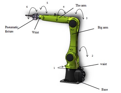
In this paper, a six-axle handling robot is designed, which consists of base, waist, arm, arm, wrist and pneumatic fixture. Among them, the pneumatic fixture fixed at the wrist end flange. This machine has six degrees of freedom: (1) Space rotation of the base (2) Space pitch of the boom (3) Space pitch of the arm (4) Space rotation of the front of the arm (5) Space pitch of the wrist (6) the space of the pneumatic fixture. The first three rotating joints determine the position of the pneumatic clamp, and the latter three turn joints determine the attitude of the pneumatic clamp. The model of the moving robot is established by the three-dimensional modeling software Solid works. Figure 1 shows the three-dimensional schematic diagram of the moving robot.
Fig. 1Schematic diagram of the overall handling of the robot
2.1. Establishment of connecting rod coordinate system
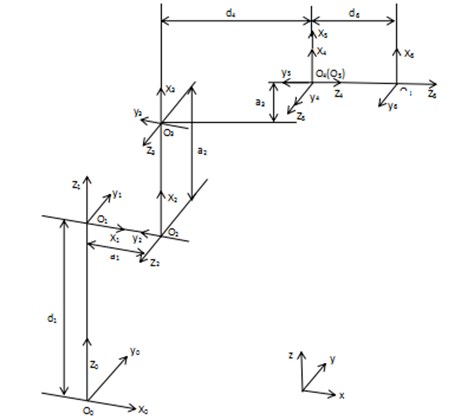
In this paper, the D-H method is used to establish the connecting rod coordinate system of the handling robot [5]. Fig. 2 shows the connecting rod coordinate system established by the six-DOF handling robot.
Fig. 2Handling robot connecting rod coordinate system
2.2. Positive kinematics solution
It can be seen from Fig. 2 that the corresponding joint parameters of the handling robot are shown in Table 1. Where ai-1 is the length of the link i-1, αi-1 is the torsion angle of the connecting rod i-1, di is the distance of the connecting rod i, θi is the corner of the connecting rod i.
Using the generalized transformation matrix:
=[cosθi-sinθi0ai-1sinθicosαi-1cosθicosαi-1-sinαi-1-disinαi-1sinθisinαi-1cosθisinαi-1cosαi-1dicosαi-10001].
Table 1Handling robot joints parameters
Link | Joint angle θi/ (°) | Joint twist angle αi-1/ (°) | Link length ai-1 / mm | Link distance di / mm | The angle of the joint is allowed to change / (°) |
1 | θ1 | 0 | 0 | 417 | 170/-170 |
2 | θ2 | 90 | 20 | 0 | 45/-190 |
3 | θ3 | 0 | 568 | 0 | 156/-120 |
4 | θ4 | 90 | 22 | 519 | 185/-185 |
5 | θ5 | -90 | 0 | 0 | 120/-120 |
6 | θ6 | 90 | 0 | 116 | 350/-350 |
The positive kinematics equation [6] of the moving robot is obtained:
nx=s6(c4s1-c1c2c3s4+c1s2s3s4)-c6(s23c1s5-c5s1s4-c1c2c3c4c5+c1c4c5s2s3),
ny=-c6(s23s1s5+c1c5s4-c2c3c4c5s1+c4c5s1s2s3)-s6(c1c4+c2c3s1s4-s1s2s3s4),
nz=c23c6s5-s23s4s6+s23c4c5c6,
ox=c6(c4s1-c1c2c3s4+c1s2s3s4)+s6(s23c1s5-c5s1s4-c1c2c3c4c5+c1c4c5s2s3),
oy=s6(s23s1s5+c1c5s4-c2c3c4c5s1+c4c5s1s2s3)-c6(c1c4+c2c3s1s4-s1s2s3s4),
oz=-s23c6s4-c23s5s6-s23c4c5s6,
ax=s23c1c5+s1s4s5+c1c2c3c4s5-c1c4s2s3s5,
ay=s23c5s1-c1s4s5+c2c3c4s1s5-c4s1s2s3s5,
az=s23c4s5-c23c5,
px=a1c1+a3c23c1+d4s23c1+a2c1c2+d6s1s4s5+d6s23c1c5
+d6c1c2c3c4s5-d6c1c4s2s3s5,
py=a1s1+a3c23s1+d4s23s1+a2c2s1+d6s23c5s1-d6c1s4s5
+d6c2c3c4s1s5-d6c4s1s2s3s5,
pz=d1-d4c23+a3s23+a2s2-d6c23c5+d6s23c4s5,
among them: ci=cosθi, si=sinθi, cij=cos(θi+θj), sij=sin(θi+θj).
In order to verify whether the transformation matrix 06T is correct, we can assign the position of each position and joint angle shown in Fig. 2 to let θ1=θ3=θ4=θ5=θ6=0, θ2= 90° be substituted into Eq. (2). As a result:
and exactly the situation shown in Fig. 2.
3. Simulation analysis of handling robot motion
3.1. The establishment of the model
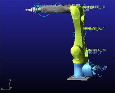
According to the kinematics model of the above-mentioned handling robot, kinematics simulation and analysis are carried out by using multi-body dynamics simulation software ADAMS. First, the three-dimensional solid model of the handling robot is built through Solid Works 3D software. To facilitate the model to open in ADAMS, save the model in parasolid (xt) format [7]. Then open the ADAMS, will create the handling of the robot sub-module into. Second, add the joint constraints of the handling robot, as shown in Table 2. Fig. 3 shows the simulation model of the handling robot after adding the constraint.
Table 2Handling constraints between robot components
Sports subtype | Sports sub name | First component | Second component |
Fixed vice | JOINT_0 | Base | Ground |
Fixed vice | JOINT_7 | Pneumatic fixture | Wrist flanges |
Rotate the pair | JOINT_1 | Base | Waist |
Rotate the pair | JOINT_2 | Waist | Big arm |
Rotate the pair | JOINT_3 | Big arm | Forearm |
Rotate the pair | JOINT_4 | Forearm | Arm rear |
Rotate the pair | JOINT_5 | Arm rear | Wrist |
Rotate the pair | JOINT_6 | Wrist | Pneumatic fixture |
Fig. 36-DOF handling robot simulation model
3.2. Simulation results and analysis
The end position of the pneumatic fixture is taken as the object of study, and the end position point MARKER_o6 is set on it. MARKER_o0 is established on the base as the origin of the coordinate. Set the rotation speed of each joint as shown in Table 3, the simulation time is 1s, measuring the end position relative to the base of the movement.
Table 3The angle of rotation of each joint (°) / s
JOINT_1 | JOINT_2 | JOINT_3 | JOINT_4 | JOINT_5 | JOINT_6 |
90 | 30 | 30 | 90 | –90 | 180 |
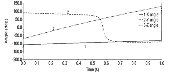
After the simulation, enter the post-processing interface. Fig. 4 shows the displacement of the end position relative to the origin of the link coordinate system. Fig. 5 shows the angular change of the end position relative to the origin of the link coordinate system.
It can be seen from Fig. 4, t= 0 s, O6 relative to O0x direction of the displacement is 655.0 mm, y direction of the displacement is 0.0 mm, z direction of the displacement is 1007.0 mm, the calculation of the two points between x, The relative displacement of y, z direction is 655 mm, 0 mm, 1007 mm, the data of the two are in full agreement. When t= 1 s, the displacement of O6 in the x, y and z directions of O0 is 116.0000, 23.5526 and 1369.3696 mm, the data of Table 3 is substituted into Eq. (2), and the displacements of O6 in the x, y and z directions of O0 are –116.0,23.552,1369.342 mm, respectively. The error in the x direction is 0, The direction of the error is 0.00255 %, in the z direction of the error is 0.00202 %, we can see that the error is very small, negligible.
It can be seen from Fig. 5, t= 0 s, O6 around the x-axis rotation angle of –180°, around the y rotation angle of 90°, around the z rotation angle of 0°, that is, O0 around x, y rotation –180°, 90°, O6 relative to the O0 attitude is [0010-10100], and (2) calculated results [0010-10100] exactly the same; t= 1 s, O6 around the x-axis rotation angle is 150°, around the y-axis rotation angle is –90°, around z The angle of rotation is 0°, that is, O0 around x, y rotation 150°, –90°, get O6 relative to O0 posture is [00-1-0.5-0.8660-0.8660.50], and (2) calculated results [00-1-0.5-0.90-0.90.50] comparison shows that the error between the two is very small, can be ignored is not small.
Fig. 4Displacement of end position point O6
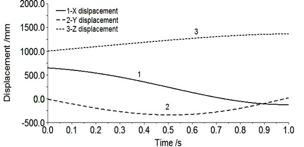
Fig. 5Angle of the end position point O6
4. Trajectory planning of handling robots
Considering the application of the moving robot in the actual production, the actual operation process of the moving robot is simulated by ADAMS. Use the STEP function in ADAMS to add the various joints of the handling robot [8, 9]. Table 4 shows the driving function of each joint, and Fig. 6 shows the trajectory of the trajectory of the pneumatic fixture at the end of the moving robot.
In the simulation environment, when the handling robot is running, there is no collision and interference between the joints, which conforms to the actual requirements of the movement. After the simulation, enter the post-processing interface.
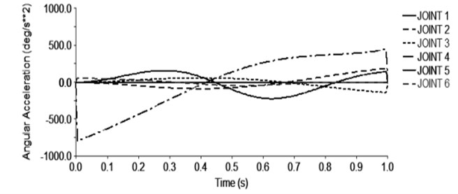
Fig. 7 shows the change of the angular velocity of each joint with time. Fig. 8 shows the change of the acceleration of each joint with time. In the trajectory planning movement of the handling robot for 7 seconds, the movement of the first few seconds is the repetition of the first 1 second movement, so only the motion angular velocity and the angular acceleration curve of the 1 second before the joint of the moving robot are intercepted. Fig. 7 shows that, as time changes, the joint angular velocity changes smoothly, where the joint 4 speed changes the largest, so the robot operation should pay special attention to the rotation of the joint 4. Figure 8 shows that the angular acceleration of each joint is not abrupt and the change is smooth. Therefore, it is known that the handling robot runs smoothly and meets the actual requirements.
Table 4Handling robots each joint drive function
Joint | Drive function |
1 | STEP(time,0.0,0.0,1.0,–33.034d)+STEP(time,1.0,0.0,3.0,0.0)+STEP(time,3.0,0.0,4.0,60.99d) +STEP(time,4.0,0.0,6.0,0.0)+STEP(time, 6.0, 0.0, 7.0, –37.956d) |
2 | STEP(time,0.0,0.0,1.0,-38.79d)+STEP(time,1.0,0.0,3.0,0.0)+STEP(time,3.0,0.0,4.0,-2.828d) +STEP(time,4.0,0.0,6.0,0.0)+STEP(time, 6.0, 0.0, 7.0, 41.618d) |
3 | STEP(time,0.0,0.0,1.0,31.486d)+STEP(time,1.0,0.0,2.0,–5.5d) +STEP(time,2.0,0.0,3.0,5.5d)+STEP(time,3.0,0.0,4.0,4.93d)+STEP(time,4.0,0.0,5.0,–5.5d) +STEP(time,5.0,0.0,6.0,5.5d)+STEP(time, 6.0, 0.0, 7.0, -36.416d) |
4 | STEP(time, 0.0, 0.0,1.0,-180d)+STEP(time,1.0,0.0,6.0,0.0) +STEP(time,6.0,0.0,7.0,180d) |
5 | STEP(time,0.0,0.0d,1.0,35d)+STEP(time,1.0,0.0,2.0,5.5d)+STEP(time,2.0,0.0,3.0,-5.5d) +STEP(time,3.0,0.0d,4.0,2.908d)+STEP(time,4.0,0.0,5.0,5.5d) +STEP(time,5.0,0.0,6.0,-5.5d)+STEP(time, 6.0, 0.0d, 7.0, –40d) |
6 | STEP(time,0.0,0.0,1.0,–13.034d)+STEP(time,1.0,0.0,3.0,0.0) +STEP(time,3.0,0.0,4.0,30.99d)+STEP(time,4.0,0.0,6.0,0.0) +STEP(time, 6.0, 0.0d, 7.0, –17.956d) |
Fig. 6Handling the robot end space trajectory
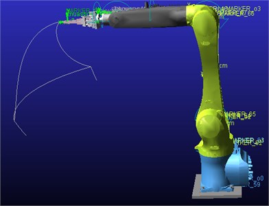
Fig. 7The speed of the joint rotation of the robot
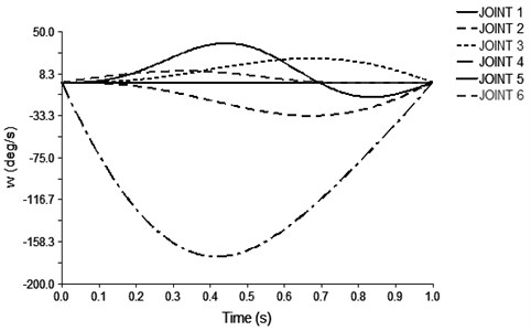
Fig. 8Handling the robot rotation angle of each joint rotation
5. Conclusion
In the automated production, the handling of industrial robots has become an indispensable tool, how effective and safe use of handling industrial robots has become a hot spot for continuous research. Using the multi-body dynamics simulation software ADAMS to simulate the movement process of the moving robot, it can not only get the corresponding speed and acceleration curve, so as to provide the basis for finding the problem and solving the problem, but also can see whether the robot has Interference and collision, reducing the physical prototype in the actual debugging damage, while saving time.
References
-
Zhu Huabing, Zhang Juan, Song Xiaobing Kinematics analysis and simulation of industrial robot based on ADAMS. Mechanical Design and Manufacturing, Vol. 5, 2013, p. 204-206.
-
Wang Zhixing, Fan Wenxin, Zhang Baocheng, et al. Kinematics analysis and simulation of industrial robot based on Matlab. Journal of Mechanical and Electrical Engineering, Vol. 29, 2012, p. 33-37.
-
Yuan An, Xue Jinji Performance analysis and simulation of robot based on ADAMS. Manufacturing Automation, Vol. 33, 2011, p. 85-89.
-
Han Xing, Li Chang, Yu Xiaoguang, et al. Simulation and simulation analysis of arc – welding robot based on ADAMS/view. Transactions of the China Welding Institution, Vol. 34, 2013, p. 69-73.
-
Zeng Jian, Lin Yizhong, Liao Xiaoping, et al. Kinematics analysis and simulation of 6R spraying robot. Mechanical Design and Manufacturing, Vol. 6, 2010, p. 145-147.
-
Cai Zixing, Xie Bing Robotics. Third Ed. Tsinghua University Press, Beijing, 2015.
-
Guo Weidong Virtual Prototyping Technology and ADAMS Application Examples Tutorial. Beijing University of Aeronautics and Astronautics Press, Beijing, 2009.
-
Tao Qiming, Ke Zunzhong Research on new method of robot trajectory planning. Machine Tools and Hydraulic, Vol. 12, 2003, p. 24-26.
-
Guo Benyin, Liu Yu, Miao Liang Analysis of working space of six-DOF micro-parallel. Journal of Changchun University of Science and Technology. Vol. 38, 2015, p. 1-5.

