Abstract
The single-tower cable-stayed bridge is one of the most popular types of bridges. Seismic design for this type of bridge, however, is rather difficult. When subjected to longitudinal earthquakes, the tower stands as the weakest part of all the bridge components. To solve this problem, a base-isolation design was developed and adopted for a practical single-tower cable-stayed bridge. In this design, laminated elastomeric bearings (EB) and liquid viscous dampers (LVD) were installed to serve as a base-isolation layer inside the tower cap. Numerical analysis was then conducted to investigate the variations of dynamic characteristics and seismic responses between conventional designs and base-isolation designs. LVD were used on the top of the transition pier to optimize the seismic system of the bridge. It was found that: i) the seismic loads acting on the bridge component were reduced as the seismic displacements increased. This was the result of amplification of the bridge vibration period by the EB in the base-isolation layer; ii) the seismic displacements were restrained by the LVD in the base-isolation layer, but the seismic forces increased due to improper parameter values; and iii) the seismic response decreased further by the transition pier’s LVD.
1. Introduction
The single-tower cable-stayed bridge, once used for more than a sixth of all cable-stayed bridges, is one of the most widely used types of bridges. There are four connection forms between the tower, pier, and beam: floating, consolidation between tower and beam, consolidation between tower and pier, and consolidation between tower, pier and beam (whole consolidation) [1]. The whole consolidation was the most widely used of these connection forms. The whole consolidation form is beneficial for static design, as it improves the bridge’s overall stiffness, reduces the deformation of the beam under vertical load, facilitates the cable adjustment, and eliminates the need for large tonnage bearings between the tower and beam [2, 3]. However, the tower was the only component that could resist longitudinal earthquake when the whole consolidation was adopted, as the longitudinal movement of the beam was released through sliding bearings installed on the top of the transition or auxiliary pier. The seismic forces of the bridge were amplified by the increase in overall stiffness. As a result, the tower was always the weakest part of the single-tower cable-stayed bridge during a longitudinal earthquake [4-6].
Base-isolation technology was born out of architectural seismic designs [7]. The principle of base-isolation is to set the isolation layer at the bottom of buildings or infrastructures to reduce its seismic response and ensure normal operation [8]. Base-isolation technology could also be applied to the seismic design of a bridge. The Rion-Antirion Bridge was a multi-tower cable-stayed bridge in an earthquake-prone area in Greece [9]. The Foundation of the bridge was placed on a 3 m thick layer of gravel. The base-isolation was achieved by sliding friction, as there was no connection between the foundation and the layer [10]. The Chi-Lu Bridge was a single-tower cable-stayed bridge damaged in the Chi-Chi Earthquake in Taiwan, 1999 [11]. Base-isolation technology was introduced to solve seismic problems. Isolation bearings were installed between the tower base and the cap to reduce the seismic loads acting on the tower [12]. The Benten Viaduct collapsed during the Hanshin Earthquake in Japan, 1995. Base-isolation technology was used during the reconstruction, with lead rubber bearings (LRB) set at the bottom of the piers [13]. Base-isolation technology is different from conventional seismic techniques and has achieved a wider range of isolation from the superstructure to substructure, and even from the foundation. Hence, base-isolation technology could be used to improve the seismic performance of a single-tower cable-stayed bridge [14-16].
In this paper, base-isolation technology was applied to and verified by a single-tower cable-stayed bridge with a main span of 155m. To begin, laminated elastomeric bearings (EB) and fluid viscous dampers (FVD) were installed inside the tower cap as a base-isolation layer. Secondly, a numerical analysis was conducted to investigate the changes of dynamic characteristics and the seismic response between the conventional design and the base-isolation design. Finally, a LVD was employed at the top of the transition pier to optimize the seismic system of the whole bridge. The seismic loads acting on the bridge component were reduced as the seismic displacement increased because the EB in the base-isolation layer amplified the vibration period of the bridge. Furthermore, the seismic displacement was restrained by the LVD at the base-isolation layer, but the seismic forces increased due to improper parameter values. Additionally, the seismic response was further decreased by the LVD in the transition pier.
2. Base-isolation design
The base-isolation design was applied to a recently built single-tower cable-stayed bridge as a case-study. Basic bridge information was introduced, including span arrangement, constraint system, and main components (e.g., the beam, tower, cable, transition pier, and foundation). The base-isolation layer, composed of EB and FVD, was set inside the tower cap. The mechanism and main parameters of these seismic-isolation devices were then described to better understand the predominant seismic performance.
2.1. Project background
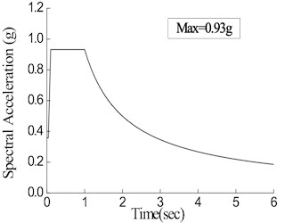
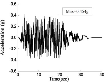
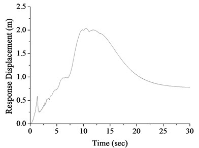
A single-tower cable-stayed bridge example with a span arrangement of 155+155 = 310 m is shown in Fig. 1. The whole consolidation was adopted as the connection form, and longitudinal sliding bearings were installed at the top of each transition pier. Each side of the cable-stayed bridge was connected by a continuous beam bridge with a span arrangement of 3×40 = 120 m. A slab section was used for the beam, with a width of 25.9 m and a height of 2.7 m at the center. The standard segment length of the beam was 8.0 m. A diamond type was employed for the tower. The total height of the tower was 103.4 m, and the height of the tower above the beam was 81.68 m. Reinforced concrete was used for the main tower structure, and pre-stressed concrete was used for the transverse beam of the tower. The upper part of the tower measured 35.4 m in height, and 5.0 m and 5.5 m in sectional size along the longitudinal and transverse direction, respectively. Similarly, the middle part of the tower measured 43.5 m in height, and 5.0 m and 3.0 m in longitudinal and transverse sectional size, respectively. In the same manner, the lower part of the tower measured 20.0 m, 5.0 m, and 3.0 m to 5.5 m, respectively. The section size of the transverse beam was 4.0 m in both the longitudinal direction and vertical direction. The thickness of the tower cap was 4.5 m, and the plane size of the tower cap was 18.5 m in the longitudinal direction and 28.0 m in the transverse direction. There were 20 bored piles beneath the tower cap, measuring 2.0 m in diameter and 60 m in length. There were 36 pairs of cables arranged for the bridge spaced 8.0 m in the beam and 1.95 m in the upper part of the tower. The dual-column solid section was used for the transition pier, with a size of 3.0 m in both the longitudinal and transverse directions. The thickness of the transition pier cap was 3.0 m, and the plane size of the pier cap was 7.0 m in the longitudinal direction and 17.0 m in the transverse direction. There were 8 bored piles beneath each cap of the transition pier with a 1.5 m diameter and a 50 m length. The strata within the exploration depth of 70.0 m were divided into artificial stacked layers, newly deposited layer, and Quaternary sediments. Silt and sand were the main types of soil. According to on-situ testing, the basic seismic acceleration at the bridge site was identified as 0.20 g. There are 7 time-history acceleration curves adopted in seismic analysis, one of which is shown in Fig. 2 including its corresponding design acceleration response spectrum curve, with a return period of 1950 years. The static and dynamic analysis were done based on Chinese bridge design codes.
Fig. 1General construction process of single-tower cable-stayed bridge (Unit: m): a) overall arrangement, b) elevation of towers and the foundation, c) side view of towers and the foundation, d) cross-section of upper part of tower, e) cross-section of middle part of tower, f) cross-section of lower part of tower, g) cross-section of transverse beam of tower, h) standard section of girders
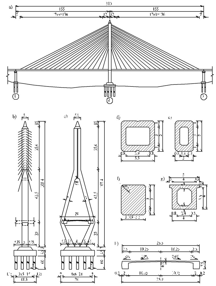
Fig. 2Seismic input: a) acceleration time history, b) acceleration response spectrum, c) displacement spectrum
a)
b)
c)
2.2. Base-isolation design for bridges
The most important part of base-isolation bridge design is to determine a reasonable position and form for the base-isolation layer. There were three options for positioning the base-isolation layer: between the substructure and foundation, inside the foundation, and between the foundation and ground. The first option was suitable for bridges with transverse frame piers, which avoid weakening the transverse stability of bridges. The second option benefits bridges that use a large-scale group pile foundation, capable of achieving a bigger transverse stability factor compared to other positions. The third option was suitable for bridges with a spread foundation, facilitating the base-isolation design of the bridge. The large-scale group pile foundation was always adopted for the single-tower cable-stayed bridge, and so the second option listed above was used for this bridge as well. The base-isolation layer was composed of seismic-isolation devices. There were many kinds of seismic-isolation devices, such as EB, LRB, high damping rubber bearing (HDR), friction pendulum bearings (FPS), and LVD [17-21]. However, three basic functions must be achieved by the seismic-isolation devices: sustainably supporting the superstructure; stably following horizontal movement of the superstructure; and efficiently dissipating energy. According to the research on the base-isolation of the Rigid Frame Bridge [22], the co-use of EB and LVD was a better method for improving isolation efficiency, and thus these two seismic-isolation devices were employed as the base-isolation layer for the single-tower cable-stayed bridge.
According to a preliminary analysis by conventional seismic system, the maximum relative displacement between beam and transition pier was 0.193 m, and the maximum moment at tower end was 1785 MN·m. However, according to Moment-curvature curve shown in Fig. 3, the seismic moment at the tower end had exceeded the capacity of the tower, which was 1150 MN·m, based on static design. As a result, base-isolation design was introduced to solve this problem.
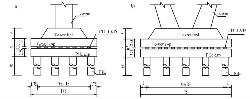
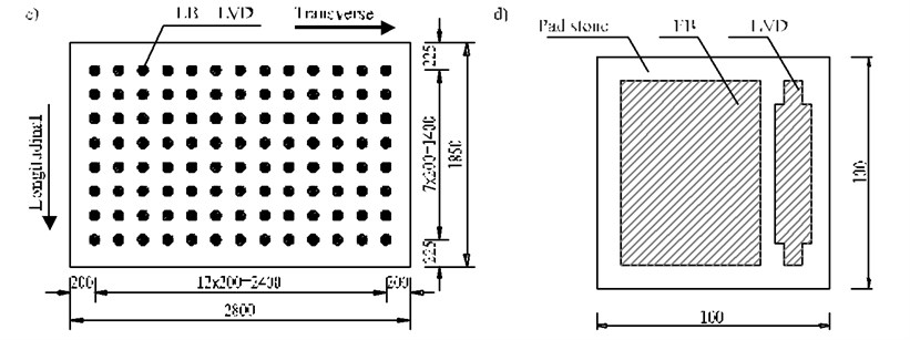
The details of the base-isolation layer for the single-tower cable-stayed bridge are shown in Fig. 3. In this paper, the cap was divided into two parts. The upper part, named the tower cap, was connected with the tower, while the lower part, named the pile cap, was connected with the pile foundation. The base-isolation layer was installed between the tower cap and pile cap, and composed of EB and LVD. The vertical load determined the number of base-isolation devices transferred from the superstructure and the parameter values of these devices were determined by parameter analysis. There were 104 sets of seismic-isolation devices inside the cap with 8 rows in the longitudinal direction and 13 rows in the transverse direction. Each set of the seismic-isolation device was composed of both EB and LVD.
Fig. 3Details of base-isolation layer (Unit: m): a) longitudinal direction, b) transverse direction, c) plan arrangement, d) local arrangement
2.3. Theoretical analysis
The numerical simulation of seismic-isolation devices was important to the seismic analysis of the base-isolation bridge. In this paper, EB and LVD were chosen as the seismic-isolation devices for the base-isolation layer of the single-tower cable-stayed bridge.
The EB was interwoven with thin rubber and steel sheets. The constitutive relations in the lateral direction could be simulated with the linear elastic model. The horizontal stiffness Kh of EB was determined with Eq. (1):
where G was the shear modulus of the rubber, Al was the effective horizontal shear area of EB, and Tr was the total depth of the rubber layer.
The LVD was composed of a cylinder, piston, and fluid. The relationship between the damping force and relative velocity of the LVD was determined by Eq. (2):
where F was the damping force; C was the damping coefficient; v was the relative velocity between the two ends of the LVD; α was the damping index with a range of 0.1 to 2.0, and from a seismic point of view, the common value of α was generally in the range of 0.2 to 1.0.
3. Seismic performance analysis
A seismic analysis was conducted for the single-tower cable-stayed bridge using the proposed base-isolation technology. Firstly, a detailed three-dimensional finite element model was established with a special emphasis on the accuracy of the constitutive relations of the seismic-isolation devices. Secondly, variations in the dynamic characteristics were systematically compared before and after the use of the base-isolation technology. Thirdly, the base-isolation layer with a better seismic performance was obtained through a LVD parameter analysis. Fourthly, from the perspective of the seismic displacement control of the beam, an optimized seismic system of the whole bridge was achieved by installing LVD between the end of the beam and the top of the transition piers. Finally, adopting the chosen parameter values of the seismic-isolation devices provided an optimized seismic response.
3.1. Finite element modeling
As shown in Fig. 4, a detailed finite element model employing base-isolation technology was developed using MIDAS/Civil to determine the static and dynamic performance of the single-tower cable-stayed bridge. The relationship between each component and its model were as follows. The models of the approach bridge were built to consider its impact on the seismic performance of the main bridge, such as the longitudinal friction force and transverse restraint force delivered to transition piers. The beam, tower, pier, and cap were all simulated with a space beam element containing a total of 316 units. The cables were simulated with a space truss element containing 72 units. Pile-soil-interaction (PSI) was considered by the “6-springs” model, and spring stiffness was calculated using the “M-method”. Boundary conditions between the beam and transition pier were considered fixed in the vertical and transverse directions, and unrestrained in the longitudinal direction.
Fig. 4Dynamic analysis model

A linear spring element was employed to simulate EB; the type of which was determined by the superstructure’s vertical force. The lateral stiffness of EB for this bridge was 4850 kN/m. The Maxwell model was used to simulate LVD; the type of which was determined by the parameter analysis. To obtain an optimized seismic system for the whole bridge, two sets of LVD were installed between the end of the beam and the top of each transition pier. Parameter values of the two types of LVD listed above are provided in Table 1.
Table 1List of parameter values
Name of parameters | Unit | Values of parameters | |
LVDs in base-isolation layer | LVDs at transition piers | ||
Damping coefficient C | kN/(m/s)α | 500, 1000, 1500, 2000, 2500, 3000 | 1000, 1500, 2000, 2500, 3000, 3500 |
Damping index | – | 0.2, 0.5, 0.8, 1.0 | 0.2, 0.5, 0.8, 1.0 |
3.2. Dynamic characteristics
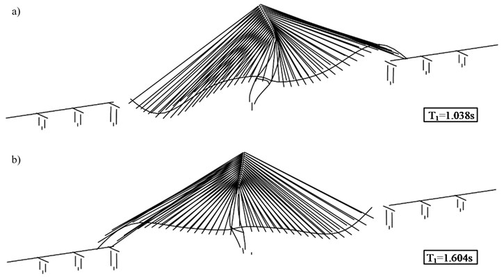
Changes in the first-order longitudinal vibration period of single-tower cable-stayed bridge are presented in Fig. 5, including the before and after of the adopted base-isolation technology. Note that when the base-isolation technology was adopted, the period increased 1.55 times. The increase was caused by the decrease of the bridge stiffness which itself was caused by the base-isolation layer. Together, this led to an increase vibration period when the bridge mass did not change. In the falling part of the acceleration spectrum curve, spectral acceleration became smaller as the vibration period increased. As a result, the bridge’s seismic response decreased correspondingly. It’s worth noting that this is the advantage of using the base-isolation design.
Fig. 5Comparisons of the first-order longitudinal vibration period: a) the case without base-isolation technology, b) the case with base-isolation technology
3.3. Numerical simulation
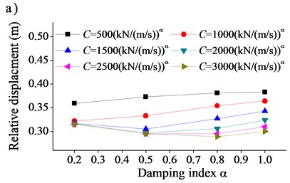
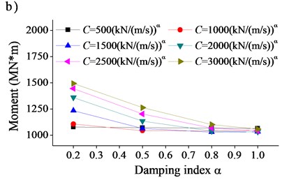
A seismic performance analysis was conducted for the single-tower cable-stayed bridge using the proposed base-isolation technology. Effects of the damping coefficient and damping index on the bridge’s seismic response are shown in Fig. 6-7. When the base-isolation technology was employed, a relative displacement between the beam and transition pier increased noticeably. At the same time, displacement at the tower end dramatically decreased. Likewise, when LVD was employed, the relative displacement decreased further as the moment would increase or decrease. When the damping coefficient increased, there was a gradual decrease in relative displacement, meaning that i) a larger decrease of relative displacement occurred when the damping index was small, and, at the same time, ii) a smaller decrease of relative displacement occurred when the damping index was large. When the damping coefficient increased, there was a gradually increasing trend for the moment, indicating that a larger increase of the moment occurred when the damping index was small, and a smaller increase of moment occurred when the damping index was large. When the damping coefficient was small, and the damping index increased, the relative displacement increased and the moment did not change noticeably. When the damping coefficient was large, and the damping index increased, the relative displacement initially decreased and then increased, while the moment decreased sharply.
The reasons for the above phenomenon were as follows. The EB used in the base-isolation layer led to a decrease in the bridge’s stiffness. Hence, the seismic load delivered to the bridge was reduced, lowering the seismic force on the bridge. But, the bridge flexibility increased when EB was adopted, which increased the seismic displacement. On the other hand, seismic displacement was effectively decreased by LVD due to its energy dissipation ability. However, the seismic force increased as isolation layer restraints were enhanced by increasing damping. According to the parameter analysis, the values of the damping coefficient and damping index were determined as follows: C=1500 kN/ (m/s)0.5, α=0.5.
Fig. 6Effect of damping coefficient C on seismic response of bridge: a) relative displacement between beam and transition pier, b) moment at tower end
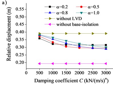
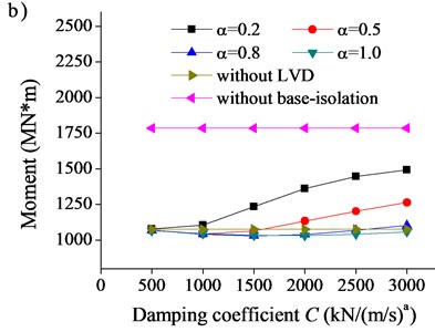
Fig. 7Effect of damping index α on seismic response of bridge: a) relative displacement between beam and transition pier, b) moment at tower end
3.4. Optimizations of seismic performance
It was beneficial for the seismic force of the bridge when the seismic displacement became larger. However, when the seismic displacement was too large, the size increase of the transition pier became difficult in terms of expansion joint design. An important part of the base-isolation design was to restrict seismic displacement to a reasonable range, and one way to do so was by installing LVD between the beam and transition pier. In the optimized scheme, LVDs in the base-isolation layer is maintained employing the chosen parameters. According to Table 1, parameter analysis was done adopting time-history method. The effect of LVD at the transition pier on the bridge’s seismic response is shown in Fig. 8. When LVD was employed at the transition, both the relative displacement and moment decreased; when the damping coefficient increased, the relative displacement and moment linearly decreased; when the damping index increased, the relative displacement and moment fairly increased. Considering the available size of the transition pier and specification of the expansion joint, the values of the damping coefficient and damping index were determined as follows: C=2500 kN/ (m/s)0.2, α=0.2.
Fig. 8Effect of LVD at transition pier on seismic response of bridge: a) relative displacement between beam and transition pier, b) moment at tower end
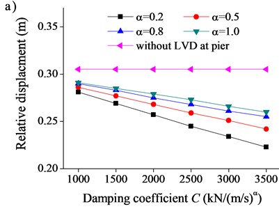
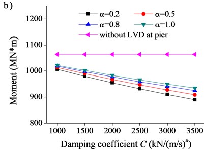
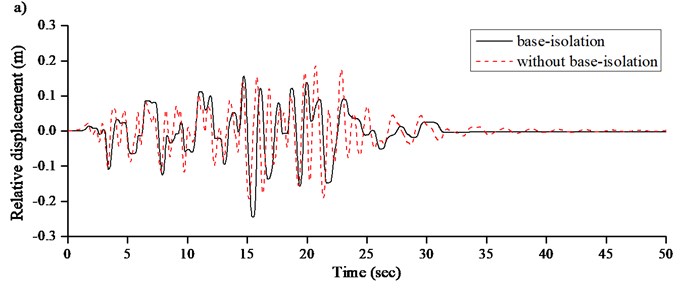
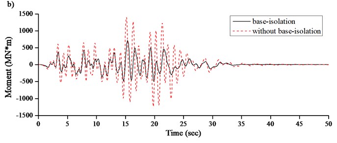
Fig. 9Seismic response of single-tower cable-stayed bridge: a) relative displacement between beam and transition pier, b) moment at tower end
3.5. Results and discussions
The results of the seismic response are presented in Fig. 9 along with the selected parameters of the seismic-isolation devices. Compared to the conventional seismic system, the optimized base-isolation system increased the maximum relative displacement from 0.193 m to 0.238 m, with an amplitude of 23.3 %. The optimized base-isolation system also decreased the maximum moment from 1785 MN·m to 932 MN·m, with an amplitude of 47.8 %. These results suggest that the risk of component damage was reduced by the optimized base-isolation system, while the seismic displacement increased to a certain extent, adjusted by structural measures.
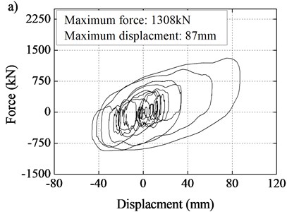
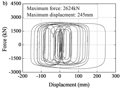
The load-displacement curves of the seismic-isolation devices in the tower cap and transition pier are shown in Fig. 10. The stiffness of the single-tower cable-stayed bridge was decreased by using EB in the base-isolation layer, which thereby reduced the seismic force as well. Additional bridge damping was provided by LVD in the base-isolation layer, thereby restraining seismic displacement. Finally, the LVD in the transition pier could further restrain an increase of seismic displacement.
Fig. 10Load-displacement curves of seismic-isolation devices: a) combination of EB and LVD at tower cap, b) LVD at transition pier
4. Conclusions
Base-isolation technology was introduced in this paper using a single-tower cable-stayed bridge as our example. Numerical analysis was conducted to investigate the seismic performance of the bridge by systematically comparing two base-isolation designs: 1) EB and LVD were installed inside the tower cap, and 2) LVD was further installed in the transition pier. The conclusions of the study are summarized as follows:
1) The bridge’s vibration period was amplified and the seismic load delivered to the bridge components was reduced by decreasing the overall stiffness of the bridge with EB used as the base-isolation layer. However, the decrease in the bridge’s overall stiffness caused an increase in seismic displacement. Seismic displacement was restrained by the LVD’s additional damping in the base-isolation layer. However, seismic forces increased as the restraints of isolation layer were enhanced by increasing damping.
2) Using LVD in the transition pier optimized the seismic system of the bridge. With the damping coefficient increased, the relative displacement and moment both decreased linearly. Reasonable LVD parameter values should be determined in accordance with the demands of the static design.
3) Compared to the conventional seismic system, the optimized base-isolation system would fairly increase the maximum relative displacement, with an amplitude of 23.3 %. However, this system could also dramatically decrease the maximum moment, with an amplitude of 47.8 %.
References
-
Li H., Liu J., Ou J. Investigation of seismic damage of cable-stayed bridges with different connection configuration. Journal of Earthquake and Tsunami, Vol. 3, Issue 3, 2009, p. 227-247.
-
Yan D., Chang C. C. Vulnerability assessment of single-pylon cable-stayed bridges using plastic limit analysis. Engineering Structures, Vol. 32, Issue 8, 2010, p. 2049-2056.
-
Shao X., Zhao H., Li L., et al. Design and experimental study of a harp-shaped single span cable-stayed bridge. Journal of Bridge Engineering, Vol. 10, Issue 6, 2005, p. 658-665.
-
Calvi G. M., Sullivan T. J., Villani A. Conceptual seismic design of cable-stayed bridges. Journal of Earthquake Engineering, Vol. 14, Issue 8, 2010, p. 1139-1171.
-
Bhagwat M., Sasmal S., Novak B., et al. Dynamic performance evaluation of straight and curved cable-stayed bridges. Bridge Structures, Vol. 5, Issues 2-3, 2009, p. 87-95.
-
Choi E., Desroches R., Nielson B. Seismic fragility of typical bridges in moderate seismic zones. Engineering Structures, Vol. 26, Issue 2, 2004, p. 187-199.
-
Kelly J. M. Aseismic base isolation: review and bibliography. Soil Dynamics and Earthquake Engineering, Vol. 5, Issue 4, 1986, p. 202-216.
-
Panchal V. R., Soni D. P. Seismic behaviour of isolated fluid storage tanks: A-state-of-the-art review. KSCE Journal of Civil Engineering, Vol. 18, Issue 4, 2014, p. 1097-1104.
-
Teyssandier J. P., Combault J., Morand P. The Rion-Antirion bridge design and construction. 12th World Conference on Earthquake Engineering, 2000, p. 1115-1127.
-
Pecker A., Teyssandier J. P. Seismic design for the foundations of the Rion Antirion Bridge. Proceedings of the Institution of Civil Engineers-Geotechnical Engineering, Vol. 131, Issue 1, 1998, p. 4-11.
-
Chang K. C., Mo Y. L., Chen C. C., et al. Lessons learned from the damaged Chi-Lu cable-stayed bridge. Journal of Bridge Engineering, Vol. 9, Issue 4, 2004, p. 343-352.
-
Chadwell C. B. Seismic Response of Single Tower Cable-Stayed Bridges. University of California, Berkeley, 2003.
-
Yoshikawa M., Hayashi H., Kawakita S., et al. Construction of Benten Viaduct, rigid-frame bridge with seismic isolators at the foot of piers. Cement and Concrete Composites, Vol. 22, Issue 1, 2000, p. 39-46.
-
Bayat M., Daneshjoo F., Nisticò N. A novel proficient and sufficient intensity measure for probabilistic analysis of skewed highway bridges. Structural Engineering and Mechanics, Vol. 55, Issue 6, 2015, p. 1177-1202.
-
Bayat M., Daneshjoo F., Nisticò N. The effect of different intensity measures and earthquake directions on the seismic assessment of skewed highway bridges. Earthquake Engineering and Engineering Vibration, Vol. 16, Issue 1, 2017, p. 165-179.
-
Pan Y., Agrawal A. K., Ghosn M., Alampalli S. Seismic fragility of multi-span simply supported steel highway bridges in New York State. II: Fragility analysis, fragility curves, and fragility surfaces. Journal of Bridge Engineering, Vol. 15, Issue 5, 2010, p. 462-472.
-
Taylor A. W., Lin A. N., Martin J. W. Performance of elastomers in isolation bearings: a literature review. Earthquake Spectra, Vol. 8, Issue 2, 1992, p. 279-303.
-
Hameed A., Koo M. S., Dai Do T., et al. Effect of lead rubber bearing characteristics on the response of seismic-isolated bridges. KSCE Journal of Civil Engineering, Vol. 12, Issue 3, 2008, p. 187-196.
-
Hwang J. S., Ku S. W. Analytical modeling of high damping rubber bearings. Journal of Structural Engineering, Vol. 123, Issue 8, 1997, p. 1029-1036.
-
Oh S. T., Kim Y. S. Experimental and analytical investigation of a seismically isolated bridge model with friction pendulum system. KSCE Journal of Civil Engineering, Vol. 2, Issue 3, 1998, p. 265-272.
-
Hou C. Y. Fluid dynamics and behavior of nonlinear viscous fluid dampers. Journal of Structural Engineering, Vol. 134, Issue 1, 2008, p. 56-63.
-
Yan B., Xia Y., Du X. Numerical investigation on seismic performance of base-isolation for Rigid Frame Bridges. Journal of Vibroengineering, Vol. 15, Issue 1, 2013, p. 395-405.
Cited by
About this article
This work was supported by Ministry of Transport of the People's Republic of China (Grant No. 2015318J38230), National Natural Science Foundation of China (Grant No. 51508405), China Beijing Municipal Party Committee Organization Department (Grant No. 2016754154700G141), Science and Technology Commission of Shanghai Municipality (Grant Nos. 17DZ1204301, 17DZ1204103), and Major Research Development Program from CCCC Second Highway Engineering Co., Ltd.

