Abstract
The resonance excitation of an optical fiber actuated by a conductive wire is studied in this paper. A novel approach based on exciting the micro-cantilever fiber at a location close to its base is proposed for this purpose. Analytical modeling is conducted on the mechanical models of this system in order to predict its behavior. The continuous Euler-Bernoulli beam equation with the effect of surrounding fluid medium is formulated as a boundary value problem. The natural frequencies of the system and its harmonic response are expanded analytically, and results are verified using Finite Element analysis. The obtained analytical solutions are used to draw conclusions on the response of the system and suggestions to optimize its performance are presented. In order to verify the idea in practice, an experimental setup that can closely resemble the system under consideration is made in the laboratory and its response to a periodic input with different frequencies are recorded. Comparison between the results of analytical formulation and experimental observations highlights the effectiveness of suggested technique in resonance vibration of optical fibers.
1. Introduction
Optical fibers are widely used in various applications in high-tech industries such as telecommunication. Scanning fiber endoscopy is one of the emerging areas for using fiber optics in advanced applications for bio-medical image acquisition purpose [1-3]. In this method, optical fiber is used as a micro-cantilever vibrating at relatively high frequencies. Currently, fibers are actuated using methods such as high voltage electro-static force [4, 5], magnetic actuation [6], and piezoelectric effects [3]. Electro-static and magnetic actuations require multiple components to induce their corresponding field and isolate it from external noises. In addition, is usually requires high voltage to maintain the electric/electromagnetic field [7]. On the other hand, using piezoelectric actuators restricts material choices to a handful of options and requires complicated and high cost methods for manufacturing such as depositing [7].
The main goal of this research is coming up with an alternative method for actuation of optical fibers in relatively high frequency to achieve large amplitude of deflection at the tip point. Amongst potential options, use of thermal actuation through a novel technique is explored. Advantages of thermal actuation include: (1) higher forces and displacement can be achieved by applying smaller voltage; (2) there is more flexibility in material selection: thermal actuators can be manufactured from most metals; (3) generally it relies on simple principles that reduces the complexity of the system substantially (for instance there is no need for coils to induce magnetic field, or directionality of crystals for PZT).
Although the thermal expansion/contraction cycles from actuator can provide the micro-cantilever with enough perturbation to induce vibrations, the amplitudes of these vibrations are relatively small keeping in mind the magnitude of thermal expansion coefficients in conventional materials, and the range of temperatures that are acceptable. Generally, operating under resonance frequency is a common technique for increasing the displacement amplitudes in vibration of MEMS devices [7]. Resonance vibrations can be induced using a wide range of actuation methods such as electrostatic [8-11], piezoelectric effect [12, 13], and thermos-mechanical [14-17]. There are benefits, drawbacks, and limitations on using each of these actuation techniques in resonance vibration. Most importantly the time constants of each actuator or in other words their ability to go through the required cycles can determine advantage of one technique over other. Other considerations such as feasibility of fabrication, energy/power consumption and long term durability can also be critical factors on making decision on the source of actuation for resonance vibration.
It has been verified that the heating/cooling cycles of thermal actuators in MEMS devices can reach frequencies as high as a few MHz [18]. This is due to their small sizes that bring their heat capacity and time constants to very small magnitudes. In addition, the extremely small size of MEMS devices makes very high temperature gradients between the heat generator and heat sink that in turn accelerates the cooling cycles. Thermal actuation can be used in various forms for dynamic actuation. Methods such as longitudinal/linear motions and bimorph effect [16], beam buckling [19], cold arm and hot arm [20] etc. The method suggested in this paper is based on actuating the micro-cantilever fiber at a location close to its clamp point. This acts as a base excitation for the beam. Komeili and Menon [21, 22] studied the response of micro-cantilever beam to thermal cycles at its base, along with sensitivity analysis on the system, using Finite Element method. Later on, they showed an analytical model for a 2 dimensional micro-cantilever excited at its base [23]. Grigorov [24] fabricated a monolithic micro-cantilever, actuator and conductive material system where the higher resistance in actuators results in heat generation and thermal expansion contraction. Their procedure was close to the base excitation idea explored here. However, in the current application it is necessary to fabricate the optical fiber separately (for optical performance) and then design a separate actuator system and attach it to the pre-made fiber.
2. Micro-cantilever
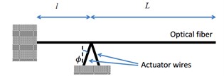
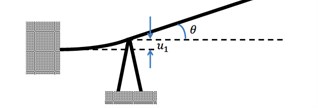
Fig. 1(a) shows the schematics of the fiber (micro-cantilever) and actuator system. As this illustration shows, actuator is attached underneath the beam at a distance, l, from the clamp point and it is extended over length, L, from the actuation point. Fig. 1(b) depicts the mechanism of fiber actuation in practice. Temperature rise inside the actuator leads to thermal expansion and eventually a displacement of u1 at the top of actuator which acts as a load/displacement perturbation at point x=l along the length of the micro-cantilever. Repeated heating and cooling of the actuator results in vibration in the beam. If the frequency of the excitation matches the natural frequency of the system resonance occurs and large amplitudes of vibrations are obtained in the beam [25]. Apparently, vibration at resonance frequency increases the efficiency of the system by providing more deflection at the tip point (final goal of this mechanical device), with smaller amount of input power compared to non-resonance cases. Therefore, study of the free vibration – natural frequencies – as well as harmonic response of the system is crucial for optimum design.
Fig. 1a) Geometry of the micro-cantilever system; b) actuation mechanism
a)
b)
For the sake of analysis, the system in Fig. 1 is split into two parts which includes: (1) actuation part; (2) beam part. The governing equations for each is developed keeping in mind its interaction with the other. Then, equations are combined to come up with the general dynamic equation for the system. Actuation part consist of the section of the beam from the clamp point to the point that actuator is connected to the beam (i.e, x<l) and includes actuation wires. Beam part is the span of the beam after the actuator (i.e, l<x<l+L).
2.1. Actuation part model
Actuators in this system are performing as longitudinal stiffness elements placed underneath the beam. So, stiffness of each actuator wire, Kwire, is:
where Awire, Lwire and Ewire are the cross sectional area, length and Young’s moduli of each individual wire, respectively. These elements are acting as parallel springs (with an angle) in conjunction with the section of beam from the clamp point to the connection point (i.e, x=l). Stiffness of this section of the beam, Kbeam, is provided from basic beam deflection equations and tables [26]:
where Ebeam and I are the Young moduli of beam material and the second moment of inertia of beam cross section. Similarly, the slope at the end point of the actuation section, θ, can be found via:
where Fb shows the total reaction, force applied on the beam inside the actuator part with length l, from actuator wires and the beam part. Taking into account the combined effects of force and thermal expansion and using the superposition method, the displacement at the top of actuator can be written as:
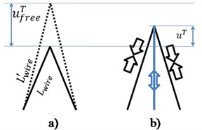
Fig. 2a) Thermal elongation in the actuator wires if not connected to the beam; b) effective thermal elongation in the actuator connected to the beam
In Eq. (4), uFA represents the component of displacement from the applied forces between actuator part and the beam part, and uTA is the displacement due to temperature change and elongation in the actuator. According to superposition, each can be found by ignoring the other and solving the mechanics of materials equations with respect to that particular effect. For instance, the relation for the applied/interaction force between actuator part and the beam part, FA, and the force induce displacement, uFA, is found via:
where ϕ is the angle made between actuator wires and vertical axis (see Fig. 1).
Details of finding uTA can be described as following using Fig. 2. Superposition is used here again to find the total displacement at the top of the actuator. First, without the beam stiffness, uTfree is found as shown in Fig. 2(a). From basic geometry, length of actuator wires after temperature change, L'wire, can be formulated as:
where αwire is the coefficient of linear thermal expansion for the actuator material and ΔT is the change in the temperature. Expanding the above equation and ignoring the terms with O(α2) and O([uTfree]2) results in the linearized equation:
Note that uTfree is a free expansion without any force involved. However, adding the beam stiffness that resists this displacement, results in compression in the actuator elements and upward elastic deflection (tension in the analogous stiffness element) in the beam section of the actuation part. The interaction results in a middle ground displacement between 0 and uTfree found via:
Combing Eqs. (4), (5) and (8), governing equation in the actuator part that relates reaction force (FA), degree of freedom (uA), and thermal actuation (ΔT) can be defined as:
2.2. Beam part model
Given small deformations, the equation of motion for a long narrow beam is as follows [25]:
where u(x,t) is vertical displacement along the beam; m signifies the weight per unit length of the beam, and distributed load on the beam (from fluid forces along the beam) is shown with q(x,t). The spatial coordinates, x and t, are the coordinate along the length of the beam, and time, respectively. Given the initial and boundary conditions, we can solve the above equation. As Fig. 1(b) shows the following boundary conditions can be identified for this beam:
where V and M represent the shear force and bending moment on beam cross section, respectively.
To solve the differential equation presented in Eq. (1), the method of separation of variables [27] can be used via replacing u(x,t)=w(x)g(t). Keeping in mind that this system is vibrating under small deformation and only free vibration and harmonic response are tackled in this study, the time dependent component is substituted by its harmonic form, g(t)=eiωt. This results in the following forms of the equation of motion.
2.3. Effect of surrounding fluid
The harmonic form of hydrodynamic forces on the micro-cantilever, Q(x,ω), is represented via following general form [28]:
where ρ is the density of the fluid medium, b is the dominant length scale (diameter for a circle and width for a rectangle), and Γ(ω) is a dimensionless function. This equation can be stipulated through solving the fluid motion equations around a rigid beam. For a beam with circular cross section an analytical solution for Γ(ω) is available in the following form [29]:
where Re=ρωb2/(4η), andKi(x) is the modified Bessel function of second kind, and η is the viscosity of the fluid.
Therefore, Eq. (12) can be simplified to the following form:
Which is a fourth order differential equation with the following generic homogenous answer:
where the Ci coefficients are the constants of this equation; they can be determined by the boundary conditions. Using Eq. (16) in the boundary condition in Eq. (16) results in the following algebraic terms:
These five equations are summarized in a matrix form as:
where:
2.4. Free vibration analysis
The free vibration (modal) analysis of the micro-cantilever is done with no external load on the system. This can be achieved by replacing {b}={0}T. In this case, the resulting from of Eq. (18) has a non-trivial zero answer only if the determinant of A is zero (|A|=0). Therefore, the following characteristic equation is extracted for the free vibration of the beam:
It can be checked that, this characteristic equation reduces to the equation of a simple cantilever beam (i.e., 1+cos(βL)cosh(βL)=0) if D1→∞. Also, note that l→0 has the same effect, as it makes Kbeam→∞ and therefore D1→∞, after solving the indeterminate form of 0×∞, it again reduces to the characteristic equation for a regular cantilever beam. The complexity of this non-linearity equation makes it unsolvable analytically; therefore, we use numerical methods for solving it. Eq. (20) has multiple complex roots in the form of r=ωd-iϵ, where ωd is damped natural frequency, and ϵ is the attenuation (damping) in the system [30].
2.5. Harmonic response
The following form of harmonic loading is imposed on system in Eq. (19):
It must be mentioned that, this is a simplified form of the thermal excitation. The simplifications assumptions are as following:
(1) The electrical current applied to the actuators, to generate heat, can be sinusoidal/harmonic; however, because of the nature of the thermal conduction equation, the resulting temperature changes are not. Indeed, there is non-homogeneity in the temperature distribution along the length of actuator. The assumption of perfect sinusoidal ΔT(t) is a simplification of a more complex function. Nonetheless, because of the small time-constant of micro-scale systems [18], the temperature changes in the actuator can be adjusted rapidly according to the magnitude of electrical current and steady-state can be achieved rapidly (for a more detailed discussions check [21]); and
(2) Active cooling cannot be practically implemented in this system. However, assuming that, after achieving steady-state, there is a base temperature and ΔT(t)=-ΔT0+-ΔTeiωt, where (-ΔT0≥-ΔT), the above formula can be valid for the harmonic part. The constant static deformation, due to the steady-state temperature increase (-ΔT0), can be calculated easily and added to the dynamic response (superposition of static and dynamic deformation). We only consider the harmonic part of mechanical displacement.
Although Eq. (18) can be solved analytically to find the closed form of Ci coeffiecnts, it was found that the resulting closed forms leads to complex terms that does not reduce the complexity of algebraic equations and numerical computations. On the other hand, using a numerical matrix solver package for direct evaluation of Ci coefficients from its matrix form proved to be computationally and programmatically more efficient. The numerical linear algebraic (linalg) modules of NumPy package in Python programming language are used for this purpose here.
In addition to displacement that is directly calculated from the Eq. (16), the stress inside the beam can be found via [31]:
Hence:
In which z is the distance from the neutral axis of the beam.
2.5.1. Quality factor
To investigate the efficiency of this system, the quality factor is investigated. Quality factor (Q) is defined as [32]:
where Us is the maximum stored energy, and Ud is the energy loss over one cycle. Hence, we have:
It should be noted that that, Uk is from the total elastic energy stored in the actuation section, and the Ub is for the elastic bending energy stored in the beam part. By using the general form of w(x) function in Eq. (16), and having Ci coefficients, the answer to this integral is found to be:
Energy loss in this system is only due to the hydrodynamic force, fluid drag. Therefore, the energy loss over one full cycle is equal to the work done by the fluid force. Hence, we have:
where re(z) refers to the real value of complex number z, and T=f-1 is the period of cycles in oscillatory motion. Solving this integral analytically is a tedious task. Here, it is solved using numerical integration (Python NumPy package).
Alternatively, if the dissipative effects in the fluid is small (i.e., Q≫1) the following approximation can be used:
where im(z) is the imaginary component of the complex number z, and Qn is the quality factor at nth natural frequency with ωn.
3. Numerical results
The analytical formulations presented above are used to study the behavior of the micro-cantilever and draw conclusions on the design of scanning optical fiber. The effect of prominent geometrical factors and the performance of system in terms of deflections at resonance frequency and harmonic response are discussed. As mentioned before, formulations presented in Section 2 are implemented in numerical codes using open source NumPy and SciPy libraries of Python.
In the first case study the formulation in Section 2 is used to find the damped natural frequencies of a micro-cantilever, its harmonic response, and quality factor. The cantilever beam material is made out of Silica (E= 73 GPa, density ρ= 2200 kg/m3) and the actuator wires are made of Aluminum (Ebase= 71 GPa, and α= 4.0×10-51/°C. The geometrical dimensions used for this study are: optical fiber (micro-cantilever) length (L= 800 μm), diameter (d= 10 μm), the actuator distance from the clamp point (l= 100 μm). Actuator wire length (Lwire= 100 μm), diameter (dwire= 100 μm), and an actuator wire angle (ϕ= 25°) are also the selected dimensions for the actuation part. Air and water are considered for the ambient fluid with ηair= 1.98×10⁻⁵ Pa·s and ηwater= 0.0014 Pa·s; and ρair= 1.024 kg/m3, ρwater= 998 kg/m3. Effect of ambient air pressure is reflected as an increase in the density according the ideal gas laws. While air viscosity is assumed to have negligible changes due to pressure.
3.1. Free vibration
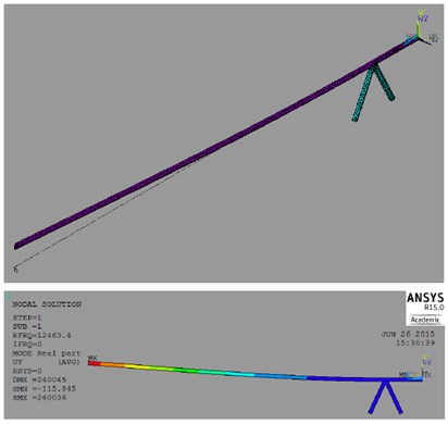
Fig. 3 show the first 3 natural frequencies of the system with the dimensions listed above, in exposure to vacuum, air (1 and 10 atm), and water. The drop in the natural frequency when exposed to a denser medium is obvious in the figure. It can be related to the fact that in conjunction to a denser fluid, more mass needs to be displaced during vibration, which in turn increases the effective mass of system and subsequently decreases the natural frequency. A comparison to the natural frequencies obtained from a finite element ANSYS model shown in Fig. 4, and the natural frequencies obtained from a simple cantilever with length L is shown in this figure to validate the formulations presented above. The ANSYS model uses a 3D representation of the current system with the described boundary conditions. Also, only one half of this model is created and meshed, however proper boundary conditions are imposed for symmetry. As it can be seen in Fig. 3, results of FEM are acceptably close to the analytical solution. Moreover, as comparing the results of simple clamped beam to the other cases shows, this system in terms of natural frequency resembles a clamped beam with length L. Further investigations on the effect of actuator wires (its dimensions and stiffness) as well as distance of the actuator to the clamp point (l), showed that these parameters have negligible effect on the natural frequency (less than 0.1 %).
Fig. 3First 3 natural frequencies predicted from the analytical model in cavity and different fluid mediums, compared to the FEM model and simple cantilever model in cavity
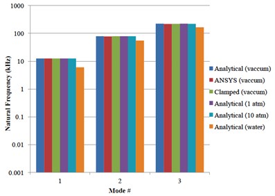
Fig. 4The finite element model used to verify the analytical model
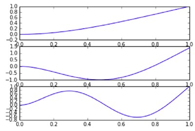
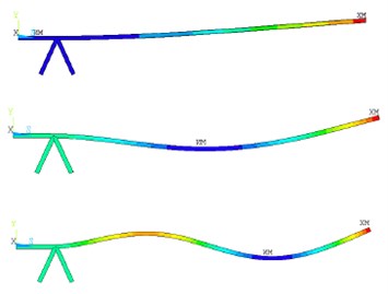
The eigenvalues of Eq. (18) was used to find the natural frequencies. Using the eigenvectors related to latter natural frequencies results in mode shapes for corresponding natural frequencies. Fig. 5, depicts mode shapes obtained for the first 3 modes calculated analytically and is compared with mode shapes extracted from ANSYS. Note that only flexural modes are taken into account here and torsional and longitudinal modes are ignored.
Fig. 5First 3 mode shapes obtained from a) analytical model; and b) ANSYS
a)
b)
3.2. Harmonic response
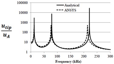
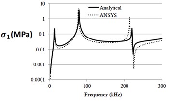
Harmonic response of the beam over a frequency range of 0 to 300 kHz is studied with -ΔT= 1 °C. Fig. 6 shows the amplitude of displacement at the tip point of the beam and the maximum stress (z=±d/2) at the mid-section of the beam. A comparison is made with an analogous ANSYS model where effect of thermal expansion is replaced by directly imposing displacements at the point that actuator is attached to the beam. Normalizing results of analytical solution to 1 nm displacement actuation, shows that there is agreeable correspondence between the results of the analytical solution and the FEM method.
Fig. 6Harmonic response of the micro-cantilever using analytical model compared to the analogous ANSYS model: a) tip displacement; b) stress magnitude for 1 nm actuation
a)
b)
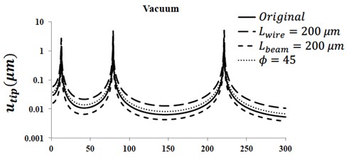
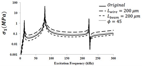
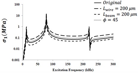
Fig. 7 shows the magnitude of tip displacement and maximum stress at the mid-span of the beam in vacuum. The harmonic response with the dimensions mentioned above are compared to the cases with change in the actuator wire length (Lwire), the actuation distance (l) and the actuator angle (ϕ). Although it was observed before that these variables do not have noticeable effect on the natural frequency, as it can be seen in this figure, they can substantially influence the tip displacement and mid-span stress values. Jumps in the magnitude of the displacement as well as stress at the frequencies that corresponds to the natural frequency are also observed in this graph. This clearly shows the resonance phenomenon. It should be mentioned that in in this case the peak points are singular point that go to infinite (no damping in resonance).
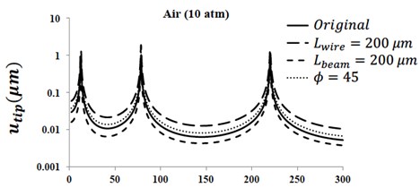
Similarly, Fig. 8 shows the effect of change in wire length (Lwire), the actuation distance (l) and the actuator angle (ϕ), while the micro-cantilever is exposed to air with 10 atm pressure. As it can be seen, the general response of system is relatively the same compared to vacuum, however, there is a noticeable drop in the magnitude of response at the resonance frequency. This is due to the effect of damping which is particularly dominant at the resonance frequency [25].
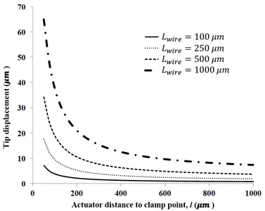
Fig. 9 illustrates the tip displacement of the micro-cantilever at its first (fundamental) frequency as a function of actuator distance from the clamp point (l) for various values of actuator wire length (Lwire) at 1 atm air pressure. As it can be seen, increasing the length of the actuator wire increases the tip displacement almost proportionally. Keeping in mind that the longer actuator wire means longer displacement at the top of the actuator Eq. (7), this result is expected. On the other hand, the tip displacement falls drastically as a result of increase in the distance from the base. The latter phenomenon can be related to the fact that shorter distance between the actuator and the base increases the slope of the beam as it can be seen in Eq. (3).
Fig. 7Harmonic response of micro-cantilever in vacuum: a) tip displacement; b) maximum stress magnitude at mid-span
a)
b)
Fig. 8Harmonic response of micro-cantilever in air (10 atm): a) tip displacement; b) maximum stress magnitude at mid-span
a)
b)
3.3. Quality factor
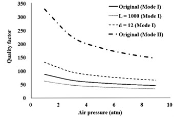
Calculating the quality factor for the system under consideration shows that the quality factor is independent of the parameters of the actuation part and only dependent on the beam part (beam length and diameter) as well as ambient pressure and mode number. Fig. 10 shows the quality factor calculated using the integration method (described in Eqs. (24-27)) for the first two modes of the original model, and changes in the length and diameter of the micro-cantilever. It must be noted that the approximated low dissipation Eq. (28) results in values that are up to –2 % higher than the values that are shown here.
Fig. 9Effect of actuator distance from the clamp point and the length of actuator wire on the tip displacement magnitude at first natural frequency
Despite the fact that each line represents a different resonance frequency (depending on mode number, and beam length and diameter), similar trends in quality factor can be noticed as a function of air pressure. The effect of air pressure on the natural frequency in each system demonstrated here is minimal (i.e., <1 %), however, a considerable change in the quality factor is observed. Increasing the air pressure results in a rapid decline in the quality factor initially but this slows down as the magnitude of pressure is increased. Increasing the beam length and/or decreasing the beam diameter result in more displacement in the beam (due to lower flexural rigidity). Higher displacement amplitudes escalate the effect of drag force and eventually decrease the quality factor, as it can be seen from the lines that represent increasing length (L= 1000) and decreasing diameter (d= 12). A remarkable observation in this figure is substantial increase in the quality factor in the second mode. Generally, the quality of factor of vibrating micro-cantilever systems are expected to increase at higher modes [33]. Nonetheless, in practice the predicted quality factor of higher modes can be affected by factors such as larger displacement gradient at higher modes, and effect of fluid compressibility [34] that are not taken into account in the simplified and linearized models.
Fig. 10Effect of actuator distance from the clamp point and the length of actuator wire on the quality factor at first natural frequency
4. Numerical results
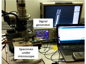
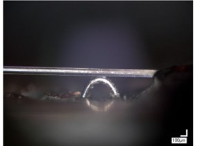
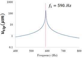
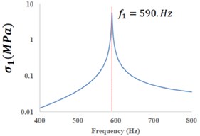
In order to verify the theoretical procedure and conclusions expanded here, a real world model of the current micro-cantilever was manufactured in the lab by authors. Fig. 11(a) shows the experimental setup for exciting the actuator using electrical signal and recording its displacements under an electronic microscope. Fig. 11(b) shows a portion of the beam comprising the connection point between the actuator and the optical fiber. The following dimensions are used to represent this system in the analytical models: fiber (micro-cantilever) length (L= 13060 μm), diameter (d= 125 μm), the actuator distance from the clamp point (l= 1450 μm), actuator wire length (Lwire= 100 μm), diameter (dwire= 127 μm), and an actuator wire angle (ϕ= 45°). Also, optical fiber is made out of Silica while actuator wires are Nichrome alloys (Ewire= 220 GPa, αwire= 14×10-61/°C)). The calculated natural frequency for the system is 590 Hz. The harmonic response depicted in Fig. 12 shows the jump in the tip displacement and the mid-span stress values for this micro-cantilever calculated analytically assuming -ΔT= 1 °C.
Fig. 11a) The experimental setup for testing the manufactured specimen; b) the actuator wire connected to the optical fiber under the microscope
a)
b)
Fig. 12The predicted harmonic response of the tested micro-cantilever assuming ΔT-= 1 °C; a) displacement magnitude; b) stress at mid-span
a)
b)
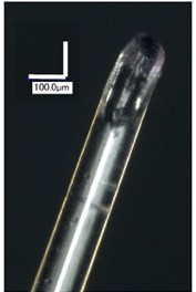
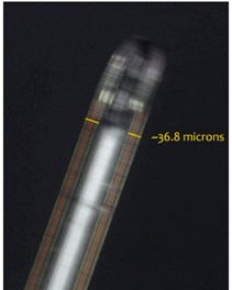
Fig. 13 compares the images captured from the tip of the optical fiber at a non-resonance frequency (a) compared to resonance frequency (b). Signal generator was programmed to sweep over frequency range that include the estimated fundamental frequency of 590 Hz with a square waveform. It was noticed that the amplitude of vibrations becomes larger at –560 Hz. Considering the small variations from the idealistic model to the manufactured micro-cantilever, this shows that overall the analytical model can fairly predict the response of the system. The larger deviation between predicted and recorded displacement amplitude is due to the simplifications described in section 2.5. Indeed, only the electric signal is controlled here and temperature change inside the actuator wire are neither uniform nor in the magnitude that is assumed here. Further studies to determine the temperature distribution inside the actuator as a function of time is required to arrive at a model that can more accurately predict the response in this system.
Fig. 13Tip of the tested optical fiber (micro-cantilever) under microscope at: a) non-resonance frequency and b) resonance frequency
a)
b)
5. Conclusions
A new actuation system for resonance vibration of optical fibers at micro-scale is proposed here. The actuation mechanism relies upon base excitation on a micro-cantilever. Actuator wires are connected to the micro-cantilever at a location close to its base. Repeated cycles of heating/cooling in these wires induce small perturbations and vibrations in the micro-cantilever (optical fiber). If the frequency of the vibration is matching the natural frequency of the system, resonance occurs and can increase the deflations in the micro-cantilever substantially.
An analytical model was presented to find the natural frequencies of the system, mode shapes and its harmonic response, taking into account the effect of surrounding fluid. This model was compared to the finite element models created in ANSYS and verified to be effective in predicting the free vibration and harmonic response. This system is separated into the actuation part (actuators and length of beam before their connection point to beam) and the beam part (span of beam after its connection point to the actuators). Results of free vibration analysis showed that the dimensions of the actuation part have negligible effect on the natural frequencies. In fact, the natural frequency of the beam can be estimated from a simple cantilever beam with a total length equal to the length of beam section. On the hand, dimensions and factors in the actuation part have considerable effect on the harmonic response of the beam, which includes the deflections and the stress magnitudes. Parameters such as distance of actuator to the base and length of actuator wire can be used to optimize the mechanical response of the system while having no impact on the natural frequency.
The quality factor in the system was reported to be independent of the actuation part and only dependent on the beam length and diameter as well the ambient fluid. It was concluded that increasing air pressure and/or decreasing the flexural rigidity of the beam results in lower quality factors. Moreover, according to the mechanical models presented here the higher mode numbers have higher quality factors. Nonetheless, the latter point might not apply to modes with relatively high deformation gradient and vibration frequency that might cause physical phenomena that are ignored in the linear models.
A laboratory model of this optical fiber and actuator system was created in the lab. Using a frequency generator to sweep over a large frequency range, showed occurrence of resonance at a particular frequency, which is close to the predicted frequency from the analytical model. However, harmonic response cannot be easily predicted here due to the fact that the real distribution of temperature inside the actuator wire is not known in this model and a simple assumption is replaced it to study the response.
Developing the time-dependent formulation for the temperature distribution in the actuator wires from an arbitrary electrical current source can improve the accuracy of this model considerably. In addition, the corresponding dynamic response under the real thermal distribution model are some of the most imminent research projects that can improve this model and help in predicting the mechanical response of this newly proposed actuator in optical fibers.
References
-
Seibel E., Smithwick Q. Unique features of optical scanning, single fiber endoscopy. Lasers in Surgery and Medicine, Vol. 183, 2002, p. 177-183.
-
Liu X., Chen Y., Cobb M., Li X. Rapid-scanning miniature endoscope for real-time forward-imaging optical coherence tomography. Conference on Lasers and Electro-Optics, San Francisco, 2004, p. 3-4.
-
Lee C., Engelbrecht C., Soper T., Helmchen F., Seibel E. Scanning fiber endoscopy with highly flexible, 1 mm catheterscopes for wide-field, full-color imaging. Journal of Biophotonics, Vol. 3, Issues 5-6, 2010, p. 385-407.
-
Munce N., Wright G., Mariampillai A., Standish B., Leung M., Tan L., Lee K., Courtney K., Teitelbaum A., Strauss B., Vitkin A., Yang V. Doppler optical coherence tomography for interventional cardiovascular guidance: in vivo feasibility and forward-viewing probe flow phantom demonstration. Journal of Biomedical Optics, Vol. 15, Issue 1, 2010, p. 011103-1.
-
Munce N., Mariampillai A., Standish B., Pop M., Anderson K., Liu G., Luk T., Courtney B., Wright G., Vitkin I., Yang V. Electrostatic forward-viewing scanning probe for Doppler optical coherence tomography using a dissipative polymer catheter. Optics Letters, Vol. 33, Issue 7, 2008, p. 657.
-
Joos K., Shen J. Miniature real-time intraoperative forward-imaging optical coherence tomography probe. Biomedical Optics Express, Vol. 4, Issue 8, 2013, p. 1342-1350.
-
Maluf N., Williams K. Introduction to Microelectromechanical Systems Engineering. Artech House Inc., Boston, 2004.
-
Jiang L., Cheung R., Hedley J., Hassan M., Harris J., Burdess J., Mehregany M., Zorman C. SiC cantilever resonators with electrothermal actuation. Sensors and Actuators A: Physical, Vol. 128, Issue 2, 2006, p. 376-386.
-
Mestrom R., Fey R., Beek J., Phan K., Nijmeijer H. Modelling the dynamics of a MEMS resonator: simulations and experiments. Sensors and Actuators A: Physical, Vol. 142, Issue 2, 2008, p. 306-315.
-
Rezazadeh G., Fathalilou M., Shabani R., Tarverdilou S., Talebian S. Dynamic characteristics and forced response of an electrostatically-actuated microbeam subjected to fluid loading. Microsystem Technologies, Vol. 15, Issue 9, 2009, p. 1355-1363.
-
Ouakad H., Younis M. The dynamic behavior of MEMS arch resonators actuated electrically. International Journal of Non-Linear Mechanics, Vol. 45, Issue 7, 2010, p. 704-713.
-
Iloh T., Ohashi T., Siiga T. Piezoelectric cantilever array for multi-probe scanning force microscopy. 9th Annual International Workshop on Micro Electro Mechanical Systems, 1996, p. 451-455.
-
Zhang W., Meng G., Li H. Adaptive vibration control of micro-cantilever beam with piezoelectric actuator in MEMS. The International Journal of Advanced Manufacturing Technology, Vol. 28, Issues 3-4, 2005, p. 321-327.
-
Blom F. Dependence of the quality factor of micromachined silicon beam resonators on pressure and geometry. Journal of Vacuum Science and Technology B: Microelectronics and Nanometer Structures, Vol. 10, Issue 1, 1992, p. 19.
-
Chen W., Chu C., Hsieh J., Fang W. A reliable single-layer out-of-plane micromachined thermal actuator. Sensors and Actuators A: Physical, Vol. 103, Issues 1-2, 2003, p. 48-58.
-
Lobontiu N., Garcia E. Mechanics of Microelectromechanical Systems. Kluwer Academic Publishers, New York, 2005.
-
Jianqiang H., Changchun Z., Junhua L., Yongning H. Dependence of the resonance frequency of thermally excited microcantilever resonators on temperature. Sensors and Actuators A: Physical, Vol. 101, Issues 1-2, 2002, p. 37-41.
-
Rahafrooz A., Pourkamali S. High-frequency thermally actuated electromechanical resonators with piezoresistive readout. IEEE Transactions on Electron Devices, Vol. 58, Issue 4, 2011, p. 1205-1214.
-
Sinclair M. A high frequency resonant scanner using thermal actuation. 15th IEEE International Conference on Micro Electro Mechanical Systems, 2002, p. 698-701.
-
Comtois J., Michalicek M., Barron C. Electrothermal actuators fabricated in four-level planarized surface micromachined polycrystalline silicon. Sensors and Actuators A: Physical, Vol. 70, Issues 1-2, 1998, p. 23-31.
-
Komeili M., Menon C. Analysis and design of thermally actuated micro-cantilevers for high frequency vibrations using finite element method. World Journal of Mechanics, Vol. 6, Issue 3, 2016, p. 94-107.
-
Komeili M., Menon C. Robust design of thermally actuated micro-cantilever using numerical simulations. International Journal of Simulation Modelling, Vol. 15, Issue 3, 2016.
-
Komeili M., Menon C. Modelling a micro-cantilever vibrating in vacuum, gas or liquid under thermal base excitation. Mechanics Research Communications, Vol. 73, 2016, p. 39-46.
-
Grigorov A. A longitudinal thermal actuation principle for mass detection using a resonant micro-cantilever in a fluid medium. Microelectronic Engineering, Vols. 73-74, 2004, p. 881-886.
-
Thomson W. Theory of Vibration with Applications. CRC Press, New York, 1996.
-
Beer F., Johnston R. DeWolf J., Mazurek D. Mechanics of Materials. McGraw-Hill, Boston, 2011.
-
Asmar N. Partial Differential Equations and Boundary Value Problems with Fourier Series. Boston, 2004.
-
Sader J. Frequency response of cantilever beams immersed in viscous fluids with applications to the atomic force microscope. Journal of Applied Physics, Vol. 84, Issue 1, 1998, p. 64.
-
Rosenhead L. Laminar Boundary Layers. Clarendon Press, Oxford, 1963.
-
Ogata K. Modern Control Engineering. Toronto, 2012.
-
Norton M., Karczub D. Fundamentals of Noise and Vibration Analysis for Engineers. Cambridge University Press, Cambridge, 2003.
-
Lobontiu N. Dynamics of Microelectromechanical Systems. Springer US, Boston, MA, 2007.
-
Van Eysden C., Sader J. Frequency response of cantilever beams immersed in viscous fluids with applications to the atomic force microscope: arbitrary mode order. Journal of Applied Physics, Vol. 101, Issue 15, 2007, p. 44908-0-11.
-
Sader J., Lee J., Manalis S. Energy dissipation in microfluidic beam resonators: dependence on mode number. Journal of Applied Physics, Vol. 108, Issue 11, 2010, p. 114507.
