Abstract
Boilers, the most troublesome components of electric power, chemical and processing plants generate high costs in unscheduled shutdowns, repairs and power replacement. Every occurrence of ruptured tubes leads to emergency shutdown of the entire plant. This paper describes the joint international effort to develop faster and more efficient methods for condition assessment and remaining life prediction for boiler tubes made of low-carbon steel. Authors have undertaken a systematic research with the major objective to correlate the results of combined nondestructive testing (NDT) with condition assessment of boiler tubes. The evaluation included non-contact wall thickness measurement with EMAT technology plus internal oxide layer measurement with specialized ultrasonics. While the first method shows the remaining tube wall thickness, thus allowing calculating total stress, the latter one has the potential to characterize microstructure degradation, which up to now could only be determined by destructive analysis. The special attention was directed towards identification and analysis of creep damage due to overheating. In recent years, techniques were developed to identify heat damage by measuring the thickness of internal oxide scale because even a thin scale can seriously impede heat transfer causing elevation of temperature in tube wall. A combined effect of wall thinning and the “degree of overheating” on tube remaining life was investigated. The uniqueness of this work lies in one of the first attempts to develop and validate a tool for methodology for condition assessment and remaining life prediction, for Steel20 tube material, while most of previous authors had concentrated on Cr-Mo steels. Another contribution is the combined treatment of two different damage mechanisms and practical utilization of two various NDT techniques. To-date, both results are treated separately, and consequently separate reject criteria exist for overheating and separate for wall thinning. As a result of work presented in this paper, a procedure was recommended to calculate the tube remaining life based on the results of two ultrasonic tests.
1. Introduction
The main objective of this project was to develop an optimum non-destructive testing (NDT) method or combination of methods that would improve the reliability of coal-fired boilers by reducing down-time related to failure of the water-wall tubes. Similar work has been continuing throughout the world for the last 20-30 years, however, the research was always concentrated on low alloys steels, usually Cr-Mo type, which are most popular for boiler application. Since this project was funded by Kazakhstan Ministry of Education and Science, it had to concentrate on local conditions in Central Asia. It was immediately clear to us that that the cost-benefit analysis that applies to power boilers in this region is very different from the analysis in the USA and Europe since the most widespread tube material is low carbon Steel20 (although Cr-Mo steels are also used in reheater and superheater sections). The carbon steel is much cheaper than Cr-Mo steels and in addition, the cost of labor for replacing fossil boiler tubing in Central Asia is considerably lower. Both of these factors can contribute to determining that some version of a “run to failure” philosophy for plant operation and maintenance may well be the most cost-effective. Within this context, it is worth mentioning that India and parts of Southeast Asia use similar boiler water wall and superheater materials to those used in Kazakhstan and that the types of coal used in their power plants has many similarities to Kazakhstan coal. Therefore, it seems that at least some of test and maintenance procedures could be successfully adapted to other Asian locations.
It has been widely accepted in the West that the main damage mechanism in Cr-Mo tubes in water-wall section of a boiler was fireside and internal corrosion and erosion causing wall thinning; therefore, ultrasonic wall thickness survey is conducted as a preventive maintenance measure. Carbon steel, however, brings new requirements as overheating and creep as well as hydrogen embrittlement should be considered as an additional and sometimes major damage mechanisms. It is generally recognized that creep may initiate in carbon steels in temperatures over 420-440 °C, which is well within the range in water-wall boiler tubes [1]. For that reason, any preventive maintenance procedures have to consider overheating as a possible cause of failure. Indeed, during numerous visits by the research team to coal-fired electric plants throughout Kazakhstan, it was found that creep damage was the main reason for tube failures and consequently, the analysis for overheating condition was the main type of preventive maintenance. The usual way to perform such test was a destructive method i.e. cutting and removing tube samples from affected section of a boiler and sending them to the lab for metallurgical analysis and evidence of overheating. Such procedures are cumbersome and time-consuming and often, the results were coming after plant start-up, hence no significant value of such analysis was realized. On the other hand, our team did not find an instance where hydrogen embrittlement would be a major cause of failure.
These initial investigations that included plant visits and literature search had concluded that in order for this research to be useful to plant operators in a specific geographical region of Central Asia, it has to concentrate on carbon steel as a material of choice for water-wall section of the boiler. At the same time, previous research results can be applied to reheater and superheater sections with Cr-Mo steel tubes. In summary, it was found that most common reasons for tube failures in Steel20 are: (i) external and internal corrosion and erosion, (ii) long-term overheating damage where the material strength gradually decreases with time, and (iii) short-term overheating, usually occurring during start-up or due to some unexpected occurrences, such as tube blockage, when tube temperature rises suddenly with consequent loss of tensile strength, so that hoop stress from internal pressure causes a violent rupture. It needs to mention at this point that both above types of failure are easy to recognize by a simple observation: while a long-term overheating causes a “thick-lip rupture” with many bulges and cracks visible around, a short-term overheating is connected with “thin-lip rupture” having sharp edges and usually no evidence of other damage around the burst [2]. Samples of actual tube failures are shown in Fig. 1.
Fig. 1Most common damage mechanisms observed in boiler water-wall with carbon steel material (Steel20): a) Surface corrosion and erosion causing wall thinning, b) thick-lip burst caused by long-term overheating and creep damage – note multiple longitudinal cracks in the vicinity of a burst
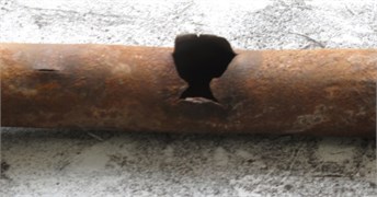
a)
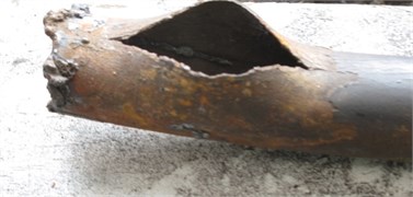
b)
2. Wall thinning measurement
As boiler ages, corrosion and erosion causes the tube wall to become thinner until it cannot sustain the internal pressure. Weak (thin-walled) tubes should be replaced or repaired long before burst can occur. One common procedure for measuring the water-wall thickness is to grind or sandblast the fire side of the water-wall to expose a bare metal and use ultrasonics (UT) to determine the wall thickness. Most often, this is done manually, every 15-20 cm of vertical height, to provide more-or-less a continuous “map” of wall thickness [3]. This approach usually provides highly reliable results but, due to laborious preparation process (sandblasting, need to erect scaffolding) the inspection is costly and takes long time. In addition, the conventional ultrasonic method requires a liquid couplant in order to transmit ultrasound wave into the metal and for that reason it is hard to automate – mechanical scanning have difficulties maintaining good coupling between the ultrasonic transducer and the boiler tube [4].
One of the goals of this research was the improvement to existing methods of tube evaluation, therefore a feasibility of using EMAT (ElectroMagnetic Acoustic Transducer) was evaluated for specific conditions, i.e. operating parameters and type of fuel/coal for Central Asian coal-fired electric plants. EMAT offers certain advantages over standard UT – no need for tube cleaning and couplant, therefore it brings a potential for significant cost reduction [5]. Additionally, EMAT allows to obtain continuous thickness measurement throughout entire tube length and further, to eliminate human labor and need for scaffolding by using robotic equipment, so more thickness data is obtained in a shorter time [6].
The economic advantages of EMAT are best described by comparing it with standard ultrasonic thickness measurement. Table 1 below shows the savings that can be realized during a boiler tube inspection with cleaning and sandblasting operations, which are usually done on a “critical path”, thus directly adding to outage duration. This calculation is shown for US conditions for a 500 MW boiler that is typical of those used in the power generation industry [7]. The power replacement cost is assumed to be $40/MWh but it should be noted that this cost may vary widely depending on the market conditions, season, etc. Further, manual EMAT was assumed but it has to be realized that robotic EMAT would additionally eliminate the cost of scaffolding.
Table 1Cost comparison for manual EMAT vs. standard UT thickness measurement of boiler tubes
EMAT no cleaning required | Standard ultrasonicswith tube cleaning | |
Cost of scaffolding | $40.000 | $40.000 |
Cost of sandblasting/cleaning | 0 | $35.000 |
Cost of NDT inspection | $35.000 | $40.000 |
Duration of lost power | 2 days (48 hrs) | 5 days (120 hrs) |
Cost of lost power | $960.000 (500 MW × 48 hrs × $40/MWh) | $2.400.000 (500 MW × 120 hrs × $40/MWh) |
Total snspection cost | $1.035.000 | $2.515.000 |
Savings EMAT vs UT | $1.480.000 | N/A |
The net result is a significant savings of $1.5 Mln but also that 36.000 MWh is saved due to the plant being able to shorten the outage by 3 days. Thus, the procedures developed here could result in eliminating the less efficient and most polluting generation plants or in the construction of fewer new plants. Further, if only one most polluting and oldest electric plant will be closed down due to this work, there would be a reduction CO2 emissions by 270.000 Tons, (assuming 0.25 kg/1 kWhr).
Technically, EMAT method relies on ultrasonic principle, however, while in standard UT system, ultrasonic wave is generated by a piezoelectric effect of a crystal transducer, EMAT generates such wave directly in tube material by electromagnetic method [8]. Fig. 2 shows the principle of operation and a typical design of EMAT transducers. The EMAT transducer has a strong permanent magnet, usually Neodymium-type and a spiral coil supplied with a current of high frequency (1-2 MHz). The current in the coil induces eddy currents on the surface of tested tube and the magnet “pushes” those currents into the tube in the form of elastic wave with ultrasonic velocity, characteristic for a given metal. In the matter of fact, there are two ways that EMATs can generate elastic energy directly in the boiler water-wall. The first is via the “Lorentz force” mechanism where interaction between an applied magnetic field and induced eddy currents produces an elastic driving force. The second is through magnetostriction (MS), which is a magneto-elastic phenomenon where an alternating magnetic field generates an alternating elastic force, usually at the alternating field frequency. While the Lorentz force mechanism has been demonstrated to work well on boiler tubes, Lorentz force EMAT systems require much higher magnetization and are heavier and costlier than their magnetostrictive (MS) counterparts. The steel surface, especially for steels used for water-wall tubes has low magnetostrictive properties and for that reason, clean tubes cannot generate sufficient EMAT signal for useful inspection. However, when the metal is exposed to conditions commonly encountered in the fire box of coal-fired boilers (temperatures over 400-450 °C), a tightly bonded scale having a large MS coefficient is formed [9]. Elastic waves generated via this MS require very little excitation power and can result in very accurate thickness measurements.
Fig. 2a) Principle of EMAT operation and b) a typical design of EMAT transducer for thickness measurement
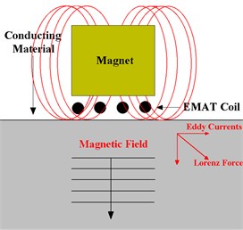
a)
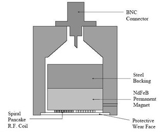
b)
EMAT transducers can work with general-purpose ultrasonic instruments with certain modifications, most important being the adequate initial pulse, at least 400 V. Fig. 3 shows the EMAT transducer coupled with standard off-shelf UT equipment and how the manual inspection is done on boiler tubes.
Fig. 3a) EMAT transducer coupled with a popular standard UT instrument MS335 and b) the manual EMAT thickness measurement performed on boiler tubes
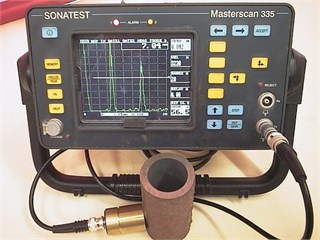
a)
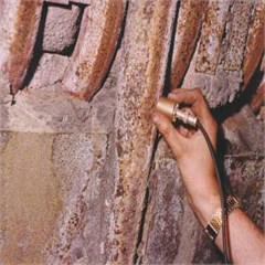
b)
The authors have a long experience with using EMAT for boiler tube measurement throughout the world. All transducers shown in this paper were designed and built at Magnetic Development, Inc. Prior to using EMAT in Central Asia, the accuracy of this technology and its comparison to conventional ultrasonics was established by numerous laboratory and field evaluation in USA and UK. Most exhaustive was an independent laboratory and field evaluation performed at GE Inspection Services, Inc. office in Huntersville, NC. The objective was to determine the accuracy, repeatability, defect resolution and field readiness. All these parameters were comparable with standard UT technique with the understanding that tubes had to be cleaned and liquid couplant had to be applied for the latter. Following the laboratory evaluation, the field data was collected at Potomac Electric’s Dickerson Station, Unit 2. The area of the boiler was selected to perform EMAT thickness measurement before sandblasting and UT measurement after sandblasting with the purpose to evaluate the accuracy of EMAT. A total of 708 wall thickness readings were taken on waterwall tubes at various elevations. The results of this comparison showed that EMAT results were very close to those obtained with standard UT. Out of 708 readings, 600 (85 %) were within +0.010” tolerance and 97 % of readings were within +0.013” tolerance [7]. It was concluded that EMAT provides accurate data and therefore offers an attractive possibility for significant cost cutting in the electric power generation industry. By eliminating cleaning, the inspection task can be completed much faster, saving the electric utility a significant amount of time and cost. In addition, a liquid couplant is not used; this further simplifies the test so more measurements can be made in a single shift and testing can be done at much higher temperatures.
The important part of feasibility study for using EMAT in Central Asian coal-fired electric plants was determination whether external corrosion scale has adequate magnetostrictive properties to generate useful EMAT signal. This depends on boiler operating parameters, temperatures, pressures, type of coil, burning conditions that determine the chemical composition of corrosive scale. The high temperatures, over 400-450 °C in the boiler causes the reaction between steel tube material and steam and flue gas producing hard, adhering scale with high contents of iron oxides. The scale is first produced on tube external surface, directly exposed to the flame, where temperatures are highest. For the purpose of obtaining magnetostrictive coupling between EMAT transducer and the tube it is not, however critical where the scale is located as good indications were obtained with scale on either surface while testing from the outside. More important than location is the chemical composition of the scale, determining its magnetostrictive properties and its adherence to the parent metal. The scale thickness, even so emphasized in many previous publications was found not to be that important as authors were able to obtain good EMAT indications through scale ranging from less than few microns to 7 mm thick [10]. In majority of tube samples collected from Central Asian coal-fired plants by these authors, EMAT signals could be generated through the scale ranging from 0.02-3 mm thick. In few cases, the scale was not formed uniformly throughout the fire box, and accurate thickness measurements could not be always obtained. Additionally, the MS coefficient that determines the strength of elastic wave signals can vary dramatically with location within the fire box that was visible by EMAT signal amplitude. In order to determine the chemical composition of the scale and to compare it to boilers in other regions of the world, the spectrometry was performed with further investigation by Scanning Electron Microscope (SEM). Fig. 4 shows two microphotographs of external scale with various thicknesses, various degree of adherence to parent tube metal with their corresponding chemical composition.
Further phase analysis determined that the prevalent chemical compound in the scale was hematite (Fe2O3) with 65-70 % content with remaining compounds being iron silicate, iron manganese oxide and austenite. The presence of highly corrosive Cl was observed as well as Na, Al and Si which indicate that corrosion was caused by fusion of ash particles [11]. Neither chemical composition nor ferrous oxides contents differed from typical values obtained in other regions of the world. Also, EMAT signal characteristics and its variation in amplitude were both similar to usual results in USA and elsewhere. Occasional lack of coupling was most probably caused by non-adherence or loose adherence of the scale to tube material. This issue can be managed through proper design of the instrumentation, especially by increasing the strength of a magnet in EMAT transducer. Indeed, the research is now continuing with designing new transducers equipped with strongest Nd-Fe-B permanent magnets available on the market [12]. While existing transducers used magnets with energy of 32-35 MGsOe, the new series being fabricated now will use 53-55 MGsOe, which is 55 % energy increase.
Fig. 4Microphotographs of two (2) samples with external oxide scale of various thickness with their corresponding chemical analysis. A solid EMAT signal was obtained for the sample on the a) while the sample on the b) has produces only a sparse signal. This was most probably due to lack of adherence between the scale and parent metal in the b) sample [13]
![Microphotographs of two (2) samples with external oxide scale of various thickness with their corresponding chemical analysis. A solid EMAT signal was obtained for the sample on the a) while the sample on the b) has produces only a sparse signal. This was most probably due to lack of adherence between the scale and parent metal in the b) sample [13]](https://static-01.extrica.com/articles/18219/18219-img7.jpg)
a)
![Microphotographs of two (2) samples with external oxide scale of various thickness with their corresponding chemical analysis. A solid EMAT signal was obtained for the sample on the a) while the sample on the b) has produces only a sparse signal. This was most probably due to lack of adherence between the scale and parent metal in the b) sample [13]](https://static-01.extrica.com/articles/18219/18219-img8.jpg)
b)
![Microphotographs of two (2) samples with external oxide scale of various thickness with their corresponding chemical analysis. A solid EMAT signal was obtained for the sample on the a) while the sample on the b) has produces only a sparse signal. This was most probably due to lack of adherence between the scale and parent metal in the b) sample [13]](https://static-01.extrica.com/articles/18219/18219-img9.jpg)
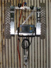
Based on the research to-date, the usefulness of EMAT in Central Asia coal-fired electric stations was well proven. First, it was determined that corrosion and erosion wall thinning is indeed one of the major damage mechanisms experienced in this region of the world where coal is a fuel of choice in over 60-70 % of all generating units. Further, authors were able to obtain EMAT signals in a great majority of all visited plants even though operating conditions differed from plant to plant and there were great variations in scale thickness. Its chemical composition was similar to other geographical locations. This research was able to formulate assumptions for better design of transducers to be optimum for given conditions. The prototype with a stronger magnet and optimized coil design has been fabricated and is shown in Fig. 5. The design of this transducer had considered its application with a robotic magnetic crawler for automatic boiler tube inspection. The prototype of such device was built at Tennessee Technological University (see Fig. 6) and its evaluation with our transducer was conducted by these authors under the auspices of Electric Power Research Institute of Palo Alto, A.
Fig. 5Prototype of EMAT transducer designed for robotic crawler application
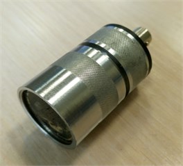
Fig. 6Magnetic crawler for EMAT
3. Overheating failures
Two types of overheating failures in water-wall boiler tubes are usually occurring: a short-term and long-term overheating. This was initially discussed above but for plant personnel, it is most important to recognize the root causes of this damage and to able to prevent them. There are numerous past publications, handbooks and individual plant maintenance procedures that discuss this issue and in this paper, we will concentrate on application of non-destructive test methods and their role in preventive maintenance and remaining life assessment (RLA). The main purpose will be to ascertain that failures will not occur between maintenance intervals and therefore, plant operating history, past metallurgical and NDT examinations and their results as well as fracture mechanics calculations have to be used to setup the proper inspection schedule, intervals between inspections and test procedures. The RLA is very often mixed with “life extension”. While the procedures described here may or may not extend the life of the boiler, but nevertheless, they should result in significant financial benefits, by increasing plant availability. For that reason, NDT and testing in general should be seen as a profit, and not as a cost.
A tube rupture caused by overheating may occur within few minutes or take several years. A long-term overheating can be usually detected in its early stage by several non-destructive and destructive test methods, while short-term overheating can be compared to sudden accidents that will be very hard to predict. This type of failure is characterized by a “ductile” or “thin lip” burst that can be readily recognized by a visual examination. It is caused by a rapid and often localized heating of tube material well over operating temperature for a given steel. It is well documented that violent ruptures had occurred in carbon steel in temperatures 700-800 °C. Most likely, short-term overheating happens during plant shut-down or start-up after outage due to unstable combustion, such as excessive flue gas temperatures, displaced fireball, delayed combustion, uneven firing of fuel burners, initiating of film boiling instead of nucleate boiling in water-wall tubes. The localized overheating causes a decrease in steel tensile strength up to the point that the material cannot hold the pressure any more, and the burst occurs. The tensile strength of carbon steel drops rapidly with raising temperature, for example for steel SA192, the tensile strength at 370 MPa at room temperature drops to 270 MPa at 480 °C to 130 MPa at 600 °C and to as low as 66 MPa at 700 °C. Unfortunately, a short-term overheating failure happens suddenly and unexpectedly and therefore neither non-destructive nor destructive test cannot be of much help in detecting it prior to the event. However, good maintenance and operation practices can still decrease the possibility of such outcome. It is important that every such event is well investigated, post-mortem analysis is done and proper procedures are adopted to prevent it in the future.
On the other hand, the long-term overheating is a damage mechanism that can be detected and prevented. It is caused by a combination of long exposure to temperature that can be only slightly above the designed temperatures and stress well below the yield point. It is referred to as “creep damage” and characterizes by gradual degradation of metallurgical structure, cracks, bulges, swelling but no detectable changes in wall thickness. Creep has been researched for many years and broad literature base exists to assist plant engineers in its recognizing and preventing. The prevention should start at the designing stage to correctly select tube material to withstand the metal temperatures. Inside the boiler, the heat is transferred from burning fuel or hot gases by radiation or convection and the outside of tube is very hot – this heat is being transferred to water (in water-wall tubes) or steam (in reheater and superheater tubes) inside the tubes. The temperature gradient then exists from the outermost to innermost layer of the tube. From the standpoint of preventive maintenance, the most useful is the temperature at the middle of wall thickness, called “mid-wall metal temperature”. It is used to determine the temperature history of the tube and consequently to calculate its remaining life. The water-walls in boiler furnace face the highest temperature, which is the flame temperature. The water flowing inside the tubes carries this heat away and cools the tube, so with proper water circulation, the mid-wall temperature is kept within allowable range for the material. Mid-wall temperature is hard to determine and can only be estimated by a “rule of thumb”. For example, some authors recommend the following formula:
For water cooled tubes, such as in water-wall:
For steam cooled tubes in reheaters and superheaters:
Mid-wall temperatures in carbon steel boiler tubes are designed to be in a range of 370 °C-420 °C and its increase by 100 °C or even less may already start the process of creep deterioration. At the initial stage, creep can only be detected by destructive metallographic examination under the microscope. It starts with graphitization, i.e. changing iron carbide to graphite at high temperatures. Graphite may be distributed in irregular way, forming cavities that in turn can initiate micro-cracks, most often oriented axially. The post-mortem analysis shows thick-lip (low ductility) burst with spheroidized microstructure and creep cavities in the immediate vicinity of a rupture.
Detecting overheating. The electric power industry has been looking for a reliable non-destructive test method to detect creep damage in its early stage [14]. Such method would eliminate the need for metallographic tests, which are both destructive and expensive. Research performed in last several years throughout the world pointed to internal oxide layer as an important marker of overheating condition. The degree to which creep condition had deteriorated metal structure can be then indirectly determined by measuring the thickness of internal oxide scale in boiler tubes. Indeed, even very basic calculation of heat transfer would be able to demonstrate that in order to keep the internal tube temperature at saturation temperature; the external tube surface has to be many degrees hotter since the oxide scale has thermal conductivity approx. 15 times less than steel. Thus, the mid-wall tube temperature may reach levels high enough for creep damage to initiate. Some sources show so called “transition temperature” from non-creep affected regime to creep affected regime. Such temperature for plain carbon steel is 427 °C while for 2.25 % Cr-1 % Mo (widely used in reheater and superheater section) is 510 °C [1]. Therefore, it is relatively easy to exceed that temperature, which is only slightly higher than normal operating temperature, especially for carbon steels.
The hard, brittle iron oxide, containing magnetite and hematite can be formed on the inside and outside surfaces of steel boiler tubing. This internal oxide layer is very different from much less dense chemical deposits that can form on the inside of boiler tubes when incorrect water chemistry is used. At very high temperatures, water vapor will react with the iron in the steel to form magnetite and hydrogen and the speed of this reaction increases with temperature:
Oxygen atoms will diffuse inward through the magnetite layer, and iron atoms will diffuse outward, so the scale continues to grow even after the tube surface is completely covered. One of the reasons that scale thickness measurements provide valuable information is that its thickness can be viewed as a measure of the time that a specific portion of the boiler tube has been operating at an elevated temperature [15]. A presence of internal scale does not necessarily mean that the boiler was operated incorrectly. All boiler operating procedures are designed to tolerate short excursions into an elevated temperature and such conditions are normally unavoidable with standard operation.
Magnetite scale acts as thermal insulation on the pipe, due to its low thermal conductivity. When heat can no longer transfer efficiently from the flame through the tube into the steam inside, the tube wall will heat up to temperatures beyond the intended operating range. Long term exposure to high temperatures, combined with the very high pressure inside the tube (stress), leads to creep initiation and then characteristic deformations in a form of swelling or bulging of the metal. An extensive research has been conducted in order to develop a correlation between mid-wall temperature and a thickness of internal scale. In particular [16] shows a graph of temperature increase as a function of scale thickness. Considering that graph together with this author’s own investigations, the experimental formula was derived:
where is internal scale thickness in millimeters Eq. (3) was developed by observing metallographic structure degradation in carbon and Cr-Mo steels and estimating mid-wall temperature. It is only valid when magnetite Fe3O4 is a prevailing composite of the scale. Other chemical compounds especially phosphates can also be ingredients of the scale and they have quite different thermal conductivity. Specifically, magnesium phosphate Mg3(PO4)2 [16] causes more temperature rise as indicated by Eq. (3).
The process of scale formation begins slowly and then accelerates, because as the scale grows thicker the tube wall becomes hotter, and that in turn increases the rate of both scale growth and metal damage. Studies in the power generation industry have indicated that the effect of scale is relatively insignificant up to thicknesses of approximately 0.3 mm [17], but beyond that scale has major negative effects on temperature rise and metal degradation. This is consistent with Eq. (3) above which indicates that at such scale thickness, the temperature will rise well above “creep affected regime”.
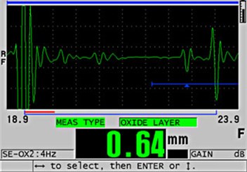
The industry experience had confirmed the importance of periodic internal scale thickness measurements as a tool for evaluating the useful operating life of boiler tubing. Over the past several years, many power plants throughout the world have indeed improved their ability to predict boiler tube failures, based, at least in part, upon an accurate knowledge of the thickness of thermally insulating scale on the inside of boiler tubing. In order to determine this thickness in nondestructive way, ultrasonic method proved to be most useful. However, first uses of this diagnostic tool done over a decade ago were cumbersome as they involved recording the amplitude-time (A-Scan) profile. The time sections of these A-Scans representing reflection from the tube inner surface were analyzed for the presence of two overlapping reflections. The first reflection comes from the interface between the tube-metal and the internal-oxide layer (if there is an internal oxide layer) and the second from the oxide-air interface (or the oxide-water interface if the measurements are made in-situ when the firebox is open for inspections during routine maintenance). The analysis of such indications was a very time-consuming and difficult process. However, as enough experience was gained, it was demonstrated that such measurements provided very useful information related to projecting when and where boiler tube failures might occur. This, in turn, provided the commercial incentive to develop a fast and reliable means to improve the inspection method. Specifically, few ultrasonic testing companies had developed a transducer and embedded software for their instruments, which now enables an internal oxide thickness measurement to be made quickly and accurately. Investigations performed within this project, were done using the Olympus 38DL hand-held instrument with transducer M2017, operating on 20 MHz frequency with a delay line. According to manufacturer, this system can measure internal oxide layers down to a minimum thickness of approximately 0.2 mm. In order to measure thinner scale, the Olympus Company offers a specialized M2091 transducer, which is a 20 MHz shear wave probe, to measure the scale down to 0.1 mm. In all cases the coupling surface must be clean and smooth and liquid couplant must be applied. Prior to measurements, the instrument has to be calibrated on scale with known thickness; such calibration reading is shown in Fig. 7.
Fig. 7Calibration reading from Olympus 38DL for internal oxide of known thickness (0.64 mm)
The extensive studies were performed to confirm the applicability of this method for Central Asian electric plant boilers. First, a total of 17 tube samples from 6 plants throughout the country of Kazakhstan were collected. Most of the samples were taken from failed tubes in water-wall and superheater sections and they were both carbon steel (steel 20) and 12Х1МФ, which is low alloy steel with 0.9-1.2 % Cr and 0.25-0.35 % Mo. Steel20 design temperature is 400 °C while 12Х1МФ is intended for 450°C. All samples were then tested according to the following regime: 1) EMAT wall thickness test (this was done at the plant to determine if the external scale has any magnetostrictive properties), 2) chemical analysis (SEM) of external scale, 3) ultrasonic measurement of internal scale thickness, 4) chemical analysis (SEM) of internal scale and microscopic measurement of its thickness, 5) metallographic structure analysis of tube metal, usually at mid-wall location for tube samples with and without internal scale. The suitability of EMAT thickness measurements (items 1 and 2) were discussed in the previous paragraph while the results for items 3-5, are described below.
UT measurement of internal scale thickness. Prior to measurement, external tube surface was prepared as follows: (i) smooth-out using only sandpaper, (ii) oxide on the outside surface has been removed with a file and (iii) the surface has been machined using a mill cutter to provide a surface with general roughness of about 50 µ (this surface roughness was chosen to be representative of what can realistically be achieved when measurements are done in-situ within a power plant). We were able to measure the internal scale thickness on nine (9) out of 17 specimens when appropriate surface preparation was done. They were all in Steel20 specimens. The absence of an internal oxide on some of the specimen is not at all surprising because they could easily have been taken from a region of the boiler where temperature conditions were not conducive to oxide formation. Another possibility was that scale thickness was below the range of the instrument. The measured scale thickness was in the range from 140-330 microns, although thinner scale was observed on few other samples visually.
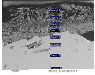
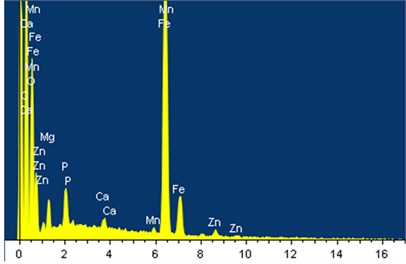
Chemical analysis of internal scale and microscopic thickness measurement. The main objective was to determine whether the prevalent scale ingredient is magnetite or some other compound – this would validate if Eq. (3) is applicable to this geographical region. Fig. 8 below shows the typical results for Steel20 tube material (all further discussion is limited to this material).
Fig. 8Microscopic and spectral analysis of internal scale in Steel20
a)
b)

The chemical analysis of internal scale did not identify the magnetite as the only ingredient and pointed to strong possibility of other compounds such as phosphates and carbonates (the latter especially in Cr-Mo steel). Further, presence of Al and Si may indicate some additional ingredients and therefore the thermal conductivity of the scale maybe quite different than that for pure magnetite. For that reason, the results of previous references and in particular Eq. (3) may not be fully applicable to local conditions in Central Asia. It is recommended that in order to evaluate the creep damage based on measurement of internal scale thickness, one will take more conservative approach than used generally in western countries.
Metallographic structure analysis. Cross sections were prepared at or close to mid-wall location and metallurgical structures were observed by optical microscope under 100X and 400X magnification. Fig. 9 below shows the comparison between samples with and without internal oxide together with appropriate discussions and explanations.
Fig. 9Metallographical structures for Steel 20. Sample without presence of internal oxide a) and with oxide scale approx. 150 micron thick b). Ferritic-pearlitic structure observed in both samples with occasional inclusions in ferrite grains. Sample on the (b) differs slightly by enlarged and elongated grains, indicating the initiation of structural degradation – classified between Stage B and C on Toft and Mardsen scale [18] (note that this scale was developed for Cr-Mo steels and not for low carbon steels)
![Metallographical structures for Steel 20. Sample without presence of internal oxide a) and with oxide scale approx. 150 micron thick b). Ferritic-pearlitic structure observed in both samples with occasional inclusions in ferrite grains. Sample on the (b) differs slightly by enlarged and elongated grains, indicating the initiation of structural degradation – classified between Stage B and C on Toft and Mardsen scale [18] (note that this scale was developed for Cr-Mo steels and not for low carbon steels)](https://static-01.extrica.com/articles/18219/18219-img16.jpg)
a) 400X
![Metallographical structures for Steel 20. Sample without presence of internal oxide a) and with oxide scale approx. 150 micron thick b). Ferritic-pearlitic structure observed in both samples with occasional inclusions in ferrite grains. Sample on the (b) differs slightly by enlarged and elongated grains, indicating the initiation of structural degradation – classified between Stage B and C on Toft and Mardsen scale [18] (note that this scale was developed for Cr-Mo steels and not for low carbon steels)](https://static-01.extrica.com/articles/18219/18219-img17.jpg)
b) 400 X
The above results have shown that creep analysis based on the thickness of internal oxide scale for Steel20 has to be more conservative than literature recommendations developed for Cr-Mo steels. Fig. 9 indicated creep initiation with only minor internal scale (150 microns), which according to previous research could be easily ignored.
4. Combined effect of overheating and wall thinning
The discussion in this paper was intended to demonstrate the value of nondestructive testing in evaluating boiler condition and in providing an important input to Remaining Life assessment (RLA). For plant engineering personnel, the immediate goal is to minimize operating costs by reducing the number of unscheduled plant shut-downs. Our approach is based upon developing improvements to the NDT methods and procedures that are commonly employed in the routine testing and how the information from these measurements is used to predict the remaining safe operating life. The final goal is to have the results of this R&D and applications engineering disseminated throughout the coal-fired electric power generating sector of Central Asian economy and pinpoint the peculiarities for this geographic and differences from other areas. The results of this work can be available for export to other countries where similar coal-fired approaches to power generation are used.
Considering two separate NDT methods discussed here, it was concluded for Central Asia that (i) for accurate wall thickness measurement, EMAT technology can be successfully used since external scale had similar chemical composition, magnetostrictive properties and range of thickness as elsewhere in the world [19] and (ii) evaluation of the degree of creep damage can be made by correlating it to the thickness of internal oxide scale, measured by specialized ultrasonics, although, more conservative approach than in western countries should be taken, The question arises how to treat a combined effect of both overheating and wall thinning, which will determine the way NDT results are utilized. To-date, both results are treated separately, and consequently separate reject criteria exist for overheating and separate for wall thinning. For example, overheating has been historically evaluated by destructive methods, i.e. removing tube samples from the boiler and sending them to the lab. Metal degradation is then determined by loss of tensile strength, change in hardness and finally by observing metallographic structure under optical microscope. Certain criteria were developed for measurable properties (strength, hardness) but evaluation of structural degradation is still somewhat subjective. Special classification methods exist, like Toft & Mardsen method [18] that classifies the condition by six (6) stages of spheroidization of carbides: from Stage A – structure not affected by creep to Stage F – structure pre-failure, demonstrating microcracks and cavities with no trace of original pearlitic areas. Each stage correlates to remaining life, providing that the same operating conditions are maintained. This method was designed for Cr-Mo steels and there is no prior history of its successful use in carbon steel. Other methods were proposed as well, one of them, based on metallographic examination by replication classifies the damage progress by four stages: isolated cavities, oriented cavities, micro-crack, and formation of macro-crack [20].
As far as wall thinning, reject criteria are simpler to determine because we are dealing with numbers instead of subjective pictures/photos of microstructure. The basic guidelines have been prescribed by ASME Code and they require that tube with certain thinning expressed in percentage wall loss be removed/replaced. The maximum allowable wall loss for water-cooled tubes (water-wall, economizer) is 30 % while for steam-cooled tubes (reheaters, superheaters) is 15 % [21].
Very limited information exists about effect of combined damage mechanisms on remaining life of boiler tubes. The most comprehensive study to-date has been done by EPRI [22] and it recommends that many factors, and not only NDT results be taken into consideration when evaluating boiler condition. General EPRI method for calculating boiler remaining life [22] recommends first to estimate mean metal temperature to the present time, considering that it is not constant and is varying due to load variation, scale build-up and other factors. There are several approaches described in literature to figure such mean temperature: hardness-based approach [23], microstructure-based approach [18] and oxide scale approach [22]. While microstructure can be only evaluated on removed sample, i.e. by destructive method, the hardness and especially thickness of oxide scale are the parameters that can be measured in non-destructive way, i.e. without the need to remove tube sample from the boiler. Once the mean temperature is determined, the Larson-Miller parameter can be calculated [24], which in turn will provide a guidance as to the time to failure at a given stress level.
The above method, however, does not consider wall thinning even though it’s well understood that it is easier to overheat thinner tube than a thicker one. Therefore, authors are recommending an improved procedure to predict a remaining tube life that considers both wall thinning and overheating. It is based on calculating the hoop stress (which considers actual wall thickness) and comparing it to Larson-Miller curve showing stress-to-rupture at certain temperature history of a tube.
First, the hoop stress is calculated from well-known strength of materials equation:
where is a pressure, is a mean tube diameter and is a wall thickness. In order to make this formula time-dependent, a constant thinning rate of , determined from periodic EMAT thickness measurements is used:
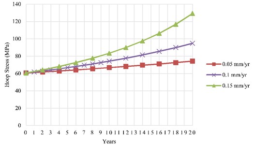
where is an initial (nominal) wall thickness and is time. An exemplary graph of hoop stress for various rates of thinning is shown in Fig. 10 below. All calculations were made for Steel20 tube of 50 mm diameter, 6 mm wall thickness at saturation pressure of 16.5 MPa.
Fig. 10Hoop stress growth in boiler tubes as a function of thinning rate
The effect of overheating is then determined by Larson-Miller curve showing stress-to-rupture at certain temperature history of a tube. This curve is time dependent rupture strength at a mean temperature:
Many studies were conducted on this problem in the past and the most comprehensive one is by EPRI [22], which recommends to estimate first the mean metal temperature to the present time. As discussed above, the mean temperature is correlated with the thickness of internal oxide layer and can be estimated from UT measurement of that thickness. Such estimate is done by means of oxide kinetics models. For this analysis, the French model [8] was used, originally developed for Cr-Mo steel and therefore it needed to be modified for carbon steel:
where is a thickness of internal oxide scale in mils, is a mean temperature in absolute scale and is service time. The coefficient is 7.25 for Cr-Mo steels. Our research has shown that for low carbon steel, should be in the range of (4.5-5.0). This was determined by observation of structural changes and relating them to the temperature.
Once the mean temperature is determined, the Larson-Miller parameter (LMP) can be calculated [23, 24], which in turn will provide a guidance as to the time to failure at a given stress level:
where LMP is the Larson-Miller parameter, is the time-to-failure. The time-to-failure is then estimated from available graphs showing LMP vs. allowable hoop stress in tube wall. This stress is then compared to its predicted growth from EMAT wall thickness periodic inspection and the remaining tube life is determined on the intersection of both curves. Below, is the numeric example for Steel20 water-wall tube, showing this procedure for actual data as in Fig. 9, i.e. tube with 150 mils of internal oxide scale as measured by ultrasonic method:
1. Determine the mean temperature from thickness of internal oxide scale. By applying Eq. (7), the mean temperature was estimated as 470 °C.
2. Calculate LMP according to Eq. (8) above by inserting previously determined mean temperature for several different values of time-to-failure hours. In this example the LMP was calculated for 470 °C temperature and time-to-failure: 10.000; 50.000; 100.000 and 150.000 hrs. The calculated values are shown in Table II below.
3. For each calculated LMP, read the corresponding value of hoop stress-to-failure from graphs available for carbon steel [22, 24], and create the curve: hoop stress () vs. time-to-failure (). For simplicity, we have reduced that graph to the following equation:
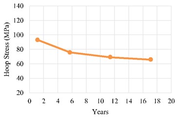
where is a hoop stress in MPa. As a result, the hoop stress to-failure data were calculated as a function of time-to-failure and they are shown in the Table 2 below:
Table 2Hoop stress as a function of time-to failure
Time-to-failure (hrs) | Time-to-failure (years) | LMP form. Eq. (8) | Hoop stress-to-failure (MPa), form. Eq. (9) |
10.000 | 1.14 | 32.1 | 93.1 |
50.000 | 5.7 | 33.0 | 75.8 |
100.000 | 11.4 | 33.45 | 69.3 |
150.000 | 17.1 | 33.69 | 66.0 |
4. Using data from Table 2, create a graph of a hoop stress as a function of time-to-failure as shown in Fig. 11(b). Authors, usually show this graph in service hours, but for simplicity, Fig. 11 shows it in full years of service, assuming 1 year = 8760 hrs.
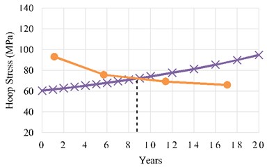
5. On the same scale, superimpose the graph for hoop stress as a function of time for a thinning rate determined by periodic EMAT tests (as in Fig. 10). The estimated remaining tube life is then determined on the intersection of both curves as shown in Fig. 11(b) (example for 0.10 mm/yr thinning rate). It needs to note, that the above analysis should be repeated and curves updated each time new NDT data are available - usually during each maintenance shutdown.
Fig. 11a) Hoop stress as a function of time-to-failure for exemplary case of tube overheated to 470°C and b) the same curve with superimposed graph of hoop stress as a function of wall thickness at steady thinning rate of 0.1 mm/yr. The tube remaining life is read on intersection of both curves; in example above, less than 9 years
a)
b)
5. Conclusions
The major objective of this work was to develop a reliable method for non-destructive evaluation of boiler tubes, which would be especially suited for Central Asia coal-fired electric power plants. A detailed survey of plants in Kazakhstan was done and boiler tube samples were obtained with various degree of damage. Chemical and metallurgical analysis has been conducted on all samples including external and internal oxide scale as well as parent metal. All this work had concluded that the major damage mechanisms were either wall thinning or overheating damage and a combination of both. Two ultrasonic test procedures were then recommended for early detection of both these damage types without necessity of removing tube from the boiler.
EMAT ultrasonic has been proven as an effective method for accurate wall thickness measurement in water-wall boiler tubes without prior cleaning. The method is also well-suited for automatic inspection with boiler-crawling robots. The rate of thinning can be determined from periodic EMAT results, as an important tool to predict the remaining tube life. It was found that the properties of external scale, specifically its composition and magnetostrictive characteristics are very similar in Central Asia to those experienced in western countries.
Indirect detection of long-term overheating condition and creep by ultrasonic measuring of internal oxide layer thickness was found to be fully applicable in Central Asia. A comparison between NDT results and metal structure examination had demonstrated that correlation exists between the scale presence and various degrees of creep degradation for carbon steel tubes. The formula was developed to estimate the temperature rise in Steel20 for various oxide scale thickness. This is an original work as all previous research was done on Cr-Mo steels. This work is being continued under grant extension to develop a full correlation between internal scale thickness and the degree of creep damage in Steel20 material.
Relatively small amount of research has been devoted in the past to combined effect of overheating and wall thinning in boiler tubes. As a result of this research, the procedure was recommended for determining tube remaining life under combined effect of thinning and overheating. This paper is one of the first attempts to develop recommendations for combined treatment of few different types of tube degradation in Steel20 while the existing reject/removal criteria treat each of these damage mechanisms separately.
References
-
Viswanathan R. Life assessment technology for fossil power plants. Integrity of Engineering Components, Vol. 20, Issue 1, 1995, p. 301-329.
-
French D. N. Metallurgical Failures in Fossil Fired Boilers. John Wiley and Son, New York, 1983, p. 143-152.
-
Nakoneczny G. J., Murphy R. D. Application of EPRI/B&W developed EMAT systems for assessing boiler tubes. International Conference on Life Management and Life Extension of Power Plant (ICOLM), China, 2000.
-
Alers G. A., et al. ASNT Nondestructive Testing Handbook. Vol. 6, Ultrasonic Testing, Section 10: Other Ultrasonic Techniques, 1990.
-
Bezlyud’ko G. Ya., et al. Portable Electromagnetic-Acoustic Thickness Meters (EMAT). Russian Journal of Nondestructive Testing, Vol. 40, Issue 4, 2004, p. 239-245.
-
Boonyaprapasorn A., et al. A prototype of inspection robot for water wall tubes in boiler. Proceedings of 3rd International Conference on Applied Robotics for the Power Industry (CARPI), Foz do Iguassu, 2014.
-
Bergander M. EMAT thickness measurement for tubes in coal fired boilers. Applied Energy, Vol. 74, Issues 3-4, 2003, p. 439-444.
-
Mayer P. A., et al. Standard Guide for Electromagnetic Acoustic Transducers (EMATS). Annual Book of ASTM Standards: Section 3, Vol. 03.03, 1996, p. 916-923.
-
Kapayeva S., Bergander M., Vakhguelt A. Ultrasonic and EMAT – important tools to analyze a combined effect of multiple damage mechanisms in boiler tubes. American Society for Nondestractive Testing (ASNT) Conference, Ultrasonics for NDT, Foxwoods, CT, 2016.
-
Bergander M., Pechacek R. Advancements in EMAT technology for boiler tube inspection. Proceedings of ASNT Fall Conference, Indianapolis, 2000.
-
Chaudhuri S. Some aspects of metallurgical assessment of boiler tubes-basic principles and case studies. Journal of Material Science and Engineering: A, Vol. 432, Issues 1-2, 2006, p. 90-99.
-
Bergander M., Hryn W. EMAT thickness measurement for tubes in coal fired boilers. Proceedings of ASNT Fall Conference, Columbus, 2001.
-
NaWon-Bae A combination of PZT and EMAT transducers for interface inspection. Journal of the Acoustical Society of America, Vol. 111, Issue 5, 2002, p. 2128-2139.
-
Lee K., Nelligan T. The use of magnetostrictive EMAT transducers on oxide scaled boiler tubes. Internal Communication by Panametrics-NDT, Waltham, Massachusetts, USA, 2005.
-
Kumar D., Mishra S. High temperature ultrasonic testing for in-situ condition monitoring of superheated steam to improve creep life of platen superheater tubes in ultra super critical power plants. International Journal of Scientific Research, Vol. 4, Issue 5, 2015.
-
Hoefs C. R., et al. The NALCO Water Handbook. 2nd Edition, NALCO Chemical Co., 1988
-
Lamping G. A., et al. Fossil-Fired Boiler Tube Inspection. Vol. 1 Nondestructive Testing Guidelines. Electric Power Research Institute (EPRI), Report CS-4633, Vol. 1, 1986.
-
Toft L. H., Mardsen R. A. The structure and properties of 1%Cr-0.5%Mo steel after service in CEGB power stations. Conference on Structural Processes in Creep, JISI/JIM, London, 1963.
-
Boynard C., et al. Influence of superficial scale in signal variation generated by EMAT on boiler tube inspection. Proceedings of European Conference of Nondestructive Testing ECNDT, 2006.
-
Sankhala K., et al. Study of microstructure degradation of boiler tubes due to creep for remaining life analysis. Journal of Engineering Research, Vol. 4, Issue 7, 2014, p. 93-99.
-
Plant Service Bulletin. Babcock and Wilcox Co., Power Generation Group, 1994.
-
Paterson I. M., Rettig T. W. Remaining Life Estimation in Boiler Pressure Parts – 2.25Cr/1Mo Superheater and Reheater Tubes. EPRI, Project RP2253-5, Final Report, Palo Alto, CA, 1987
-
Viswanathan R., et al. Methods for estimating the temperature of reheater and superheater tubes in fossil Boilers. Proceedings of the International Conference on Life Extension and Assessment, The Hague, 1988.
-
EPRI Carbon Steel Handbook. EPRI, Palo Alto, CA, 2007.
