Abstract
Firstly, this paper computed the static and dynamic characteristics of common boring bars and constrained damping boring bars respectively, and the correctness of the computational model in time-frequency domain was also validated by experiments. Modal frequencies of constrained damping boring bars were obviously more than those of common boring bars, which could effectively avoid structural resonance in low frequency and had an obvious advantage in improving anti-vibration performance of boring bars. The absolute value of the maximum vibration acceleration of common boring bars was 13.1 m/s2, while the absolute value of the maximum vibration acceleration of constrained damping boring bars was 9.1 m/s2. The maximum vibration acceleration decreased by 30.5 %. The maximum vibration displacement of common boring bars was 5.2 mm and corresponding frequency was 201 Hz. The maximum vibration displacement of constrained damping boring bars was 2.3 mm and corresponding frequency was 235 Hz. When the analyzed frequency was lower than the frequency with the maximum vibration displacement, the displacement spectrum of common boring bars had more peak values. Thus, it was clear that constrained damping boring bars had an obvious advantage in improving vibration characteristics. The impact of cutting speed, feed rate and back cutting depth on vibration characteristics was studied respectively. Results showed that the vibration of constrained damping boring bars gradually decreased with the increase of cutting speed and gradually increased with the increase of feed rate and back cutting depth. In addition, the amplitude and frequency of vibration displacement spectrum of boring bars were basically unchanged no matter how cutting parameters changed. In order to quickly predict the vibration characteristic, BP neural network and PSO-BP neural network were respectively used to predict the cutting process of boring bars. When the iteration number of BP neural network was 300, iterative error was 0.00015 which was far more than the set target error. When the iteration number of PSO-BP neural network was 215, iterative error was converged to the set target error. Therefore, PSO-BP neural network had an obvious advantage in predicting the cutting process of boring bars. In addition, the predicted result of PSO-BP neural network was consistent with the experimental result, which showed that the neural network model in this paper was effective.
1. Introduction
Deep-hole with high-speed boring is a difficult problem of machining. Boring bars is in a semi-enclosed space. With limited structure and dimensions, boring bar generally has a long, thin and cantilevered structure. In particular, large overhanging length will cause relatively small stiffness and unstable cutting process will cause vibration marks on the work-piece surface, quicken tool abrasion and generate large noises [1], which will reduce processing quality and precision. For the vibration suppression of deep-hole machining, a lot of scholars have conducted relevant studies based on the design and development of high-performance damping boring bars. The adopted method can be divided into active control and passive control from the perspective of vibration control [2].
Active control mainly applies the principle of feedback control to large boring bars with low frequency. Liu [3] used the positive and negative piezoelectric effect of piezoelectric ceramics; reversely magnified the electrical signals obtained by perceived piezoelectric patches, added them to executive piezoelectric patches and suppressed cutting vibration. Kong [4] proposed a kind of intelligent boring bars based on magnetorheological fluid, established a dynamical model for the cutting system of boring bar according to the characteristics of deep-hole cutting vibration and combined with the model to analyze the stability of cutting system. In reference [5], a robust analog controller, based on a lead-lag compensator, with simple adjustable gain and phase, suitable for the industry application, has been proposed. Also, the basic principle of an active boring bar with embedded actuator is addressed. The performance and robustness of the developed controller has been investigated and compared with an adaptive digital controller based on the feedback filtered-x algorithm. However, the inherent delay in a controller may result in tool failure when the load applied by the work-piece on the tool changes abruptly, e.g. in the engagement phase of the cutting edge. In addition, active control had a higher requirement on design and cost and was difficult to maintain. Therefore, the passive control for the vibration reduction of boring bar is proposed and widely applied. Passive control mainly converts vibration energy to other forms of energy including thermal energy through dynamical structure, impact structure and damping structure in order to achieve the damping effect. Hahn [6] placed a high-density mass block in the cavity of the boring bar and injected heavy oil into the cavity to improve the dynamic stiffness of boring bars. This method has been used to design damping boring bars with a large length-diameter ratio. Ema [7] used mass block and interstitial structure to design an impact damper and install it at the back of boring bars, which effectively reduced the radial vibration of boring bars. Yan [8] discussed the principle of frictional energy-dissipation boring bars, established a mechanical model for the link of nonlinear Coulomb dry friction, took friction parameters as the variable and inspected the vibration absorption effect of the model through adopting the method of numerical analysis. In the meanwhile, Yan developed a new-type boring bar based on friction, combined the mechanism of vibration with the theory of cutting stability, and analyzed the vibration suppression effect of boring bars under different friction conditions. Hwang [9] used epoxy composite materials with high stiffness and carbon fiber to make a boring bar with damping structure and found no obvious vibration after applying it under the condition of large overhanging. Featured with the strong ability of vibration loss and simple structure, damping structure has been widely applied to engineering structures, especially the field of aviation [10].
Based on the above analysis, current studies on damping boring bars mainly achieve the damping effect through improving the stiffness and damping capacity of boring bars [11-13]. The stiffness and damping capacity of boring bars are seldom combined for analysis and research. In fact, it is necessary to comprehensively improve the static stiffness and damping capacity of boring bars, especially the high-speed boring holes in order to improve the stability of boring bars. Structural optimization and the selection of high-quality materials for constrained damping boring bars can solve the problem of stiffness loss in the case of increasing the damping capacity of boring bars, comprehensively improve the stiffness and damping capacity of boring bars and obtain a damping boring bar with high vibration damping performance and cutting stability. As a result, this paper adopted the method of combining finite element with neural network to design constrained damping boring bars and effectively avoid the problem of high cost and low efficiency brought by experimental design.
2. Finite element model and experimental verification
2.1. Common boring bars
The model of boring bars studied in this paper was shown in Fig. 1(a) and mainly made up of three parts including head, middle parts and fixed end. The middle part of boring bars was 250 mm long with a diameter of 32 mm. The model was imported into finite element software to set material properties. Made of 40Cr alloy steel, common boring bars had density 7800 kg/m3, elasticity modulus 211 GPa and Poisson’s ratio 0.30. To ensure the precision of analysis and simulate the integrity of geometrical characteristics of model, this paper used hexahedral elements to generate the meshes of boring bars and constrained fixed end of boring bars and adopted locally fine technique for the head part. Finally, the finite element model of the boring bar contained 30,256 elements and 39,806 nodes, as shown in Fig. 1(b).
Fig. 1Geometric and finite element model of boring bars
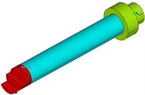
a) Geometric model
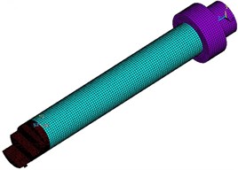
b) Finite element model
Fig. 2Constrained modes of boring bars on top 4 orders
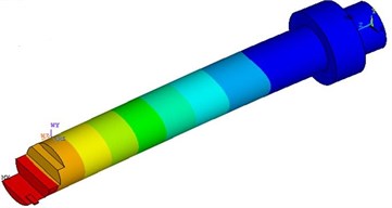
a) 200.93 Hz
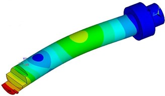
b) 2997.89 Hz
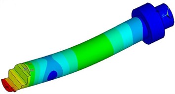
c) 3005.18 Hz
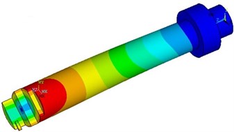
d) 3853.51 Hz
No mechanical loads will be applied in modal analysis in general. Loads will be considered only in the case of computing the impact of stress. Modal analysis does not forbid the motion of rigid body. Therefore, the correct setting of boundary conditions is very important to modal analysis because it can have an influence on the vibration mode and natural frequency of the whole structure. To simulate the boring bar under the actual working condition, the boundary conditions of boring bars were: The surface of constrained fixed end was fully constrained and the tail section of boring bars restricted axial motion. Finally, the constrained modes of boring bars on top 4 orders could be obtained, as shown in Fig. 2. As shown from Fig. 2, the constrained modes of boring bars had higher frequency and constrained modes on the second and third orders showed obvious flexural vibration. Vibration was serious mainly at the head part.
2.2. Constrained damping boring bars
The boring bar studied in Section 2.1 was only a common model. It would cause large vibration in the process of work and affect cutting quality. Therefore, it was necessary to redesign the structure of boring bars in order to restrain vibration. According to the actual working condition of boring bars, the interaction between head and work-piece needed high stiffness. Fixed end mainly played the role of clamping. It did not make much sense to redesign their structures. Only the middle part of boring bars had a large overhanging length and played a role in connecting the head with fixed end. It could be redesigned. Damping structure could effectively dissipate the energy of vibration. Thus, the position of the middle part was considered to be set as damping structure. Damping structure was mainly divided into two forms: free damping structure and constrained damping structure, as shown in Fig. 3. Free damping structure was composed of basic layer and damping layer which were combined together through glue or other methods. In constrained damping structure, damping layer was placed between two layers of elastic materials, namely between basic layer and constraint layer. Free damping structure depended on the thickness of damping layer to display its damping effect while constrained damping structure used a thin damping layer to obtain high structural loss factors. Compared with free damping structure, constrained damping structure could dissipate more vibration energy and had better damping effect [14, 15]. Therefore, constrained damping structure was applied to the boring bar to form a constrained damping boring bar, as shown in Fig. 4. Basic layer, damping layer and constraint layer of the boring bar had an outer diameter of D1=16 mm, D2=25 mm and D3=32 mm respectively. Basic layer was still made of 40Cr alloy steel. Damping layer was made of foamed aluminum alloy and had density 650 kg/m3, elasticity modulus 12 GPa and Poisson’s ratio 0.33. Constraint layer was made of YG20C hard alloy steel and had density 13400 kg/m3, elasticity modulus 400 GPa and Poisson’s ratio 0.30.
Fig. 3Two forms of damping structures
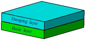
a) Free damping structure
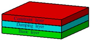
b) Constrained damping structure
The shape dimension of constrained damping boring bars was consistent with that of common boring bars. Its structure was mainly composed of three parts: basic layer, damping layer and constraint layer. In the cutting process, vibration energy generated at the head of constrained damping boring bars was delivered to basic layer. Flexure caused by vibration drove the stretch of damping layer. The extension of constraint layer was much less than that of damping layer, which prevented the extension of damping layer. When damping layer compressed, constraint layer prevented the compression of damping layer. The extension and compression of damping layer were restricted by constraint layer. Therefore, damping layer bored the alternate loads of extension and compression and vibration energy was greatly dissipated at damping layer, which could realize the goal of suppressing cutting vibration and improving the stability of cutting process [16, 17]. According to the modal computation method of common boring bars, modals of constrained damping boring bars on top 4 orders were re-computed. The result was shown in Table 1. As shown from Table 1, modal frequencies of constrained damping boring bars on top 4 orders were obviously more than those of common boring bars. Large modal frequencies could effectively avoid structural resonance and had an obvious advantage in improving the anti-vibration performance of boring bars.
Fig. 4Constrained damping boring bars

Table 1Comparison of modals for two forms of boring bars
Order | Original structure / Hz | Improved structure / Hz | Absolute error / Hz |
1 | 200.93 | 235.11 | 34.18 |
2 | 2997.89 | 3125.70 | 127.81 |
3 | 3005.18 | 3131.02 | 125.84 |
4 | 3853.51 | 4064.10 | 210.59 |
Modal frequency only reflected the static characteristics of boring bars. To verify the advantage of dynamic characteristics of constrained damping boring bars in the cutting process, excitation force was applied to the head of two kinds of boring bars and the time-domain acceleration spectrum of boring bars was extracted and transformed into frequency spectrum to make a comparison, as shown in Fig. 5. Fig. 5(a) showed that the vibration acceleration of constrained damping boring bars was obviously less than that of common boring bars. The absolute value of the maximum vibration acceleration of common boring bars was 13.1 m/s2. However, the absolute value of the maximum vibration acceleration of constrained damping boring bars was 9.1 m/s2. The maximum vibration acceleration decreased by 30.5 %. In addition, the vibration acceleration of constrained damping boring bars had small peak values. Fig. 5(b) showed a comparison of vibration displacement spectrums of two kinds of boring bars. It could be seen that the maximum vibration displacement of common boring bars was 5.2 mm and its corresponding frequency was 201 Hz; the maximum vibration displacement of constrained damping boring bars was 2.3 mm and its corresponding frequency was 235 Hz.
Fig. 5Comparison of dynamic characteristics of two forms of boring bars
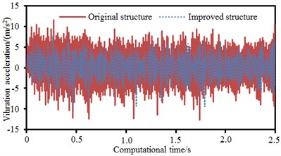
a) Vibration acceleration
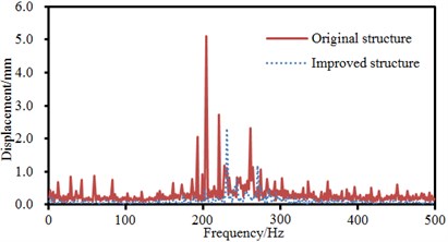
b) Vibration displacement
According to the modal frequency in Table 1, the maximum vibration displacement of boring bars resulted from the resonance caused by the natural frequency of structures. When the analyzed frequency was lower than the frequency of the maximum vibration displacement, the frequency spectrum of common boring bars showed many peak values. Thus, it was clear that constrained damping boring bars had an obvious advantage in improving vibration characteristics. The strain of constrained damping boring bars under different frequencies was extracted, as shown in Fig. 6. As shown from Fig. 6, the maximum strain of constrained damping boring bars was mainly in the position of the head. The head of boring bars touched work-piece in the cutting process and the head received the reactive force of work-piece, causing large strain.
Fig. 6Strain of constrained damping boring bars under different frequencies
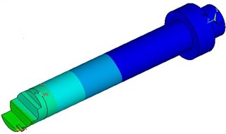
a) 100 Hz
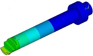
b) 200 Hz
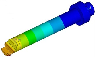
c) 300 Hz
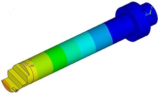
d) 400 Hz
2.3. Experimental verification of computational model
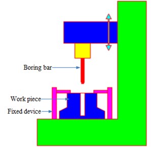
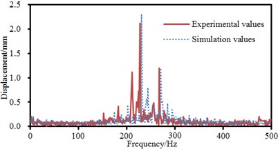
The model of constrained damping boring bars was relatively complex. Therefore, the correctness of computational result needed to be verified through experiments. As shown in Fig. 7, constrained damping boring bars were clamped in fixed equipment. Feed rate was 0.4 mm/r; cutting speed was 80 m/min; back cutting depth was 0.3 mm. An acceleration sensor was arranged at the boring bar to measure the vibration acceleration and displacement of boring bars in the cutting process and compare with numerical simulation results, as shown in Fig. 8. Fig. 8(a) displayed a comparison of time-domain vibration accelerations. It could be seen that experiment and simulation were basically the same in change trend and only peak frequencies were different. Fig. 8(b) displayed a comparison of vibration displacement spectrums of boring bars. The amplitude and corresponding frequency of experiment and numerical simulation were the same. It proved that the numerical computation model for the machining of boring bars in this paper was effective in time-frequency domains.
Fig. 7Experimental cutting process of constrained damping boring bars
3. Impact of cutting parameters on vibration characteristics
In the process of machining, the cutting parameters including cutting speed, feed rate and back cutting depth of boring bars had a great impact on vibration characteristics and machining quality. Based on the verified computation model of boring bars, the vibration characteristics of boring bars under different cutting parameters were studied.
Fig. 8Comparison of dynamic characteristics of boring bars between experiment and simulation
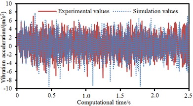
a) Vibration acceleration
b) Vibration displacement
3.1. Cutting speed
Feed rate 0.4 mm/r and back cutting depth 0.3 mm were unchanged. Cutting speed was changed from 70 m/min to 100 m/min. Step size was 10 m/min. The vibration characteristics of boring bars in time-frequency domains at every cutting speed were computed, as shown in Fig. 9. Only from the time domain, it could be seen that the absolute values of the maximum vibration accelerations of boring bars at the cutting speed of 70 m/min, 80 m/min, 90 m/min and 100 m/min were 9.1 m/s2, 9.6 m/s2, 7.6 m/s2 and 7.8 m/s2 respectively. It was unable to identify the impact rule of cutting speed on the vibration characteristics of boring bars only from the maximum vibration amplitude in time-domain accelerations. However, the vibration acceleration of boring bars at the cutting speed of 70 m/min and 90 m/min had more peak values and vibration energy was distributed more intensively. From vibration results in the frequency domain, it could be found that the maximum vibration displacements were 3.2 mm, 2.3 mm, 1.5 mm and 0.34 mm respectively at the cutting speed of 70 m/min, 80 m/min, 90 m/min and 100 m/min. In addition, the maximum vibration amplitude and frequency of boring bars in the frequency domain at different cutting speeds were the same because cutting speed would not change the natural frequency of boring bars. Within the analyzed frequency of 500 Hz, the natural frequency of boring bars was only 235.11 Hz. Therefore, boring bars would present a large vibration displacement at this frequency point under various cutting speeds. Thus, it could be noticed that the vibration of boring bars gradually decreased with the increase of cutting speed. High-precision machining could choose a large cutting speed.
3.2. Feed rate
Cutting speed 90 m/min and back cutting depth 0.3 mm were unchanged. Feed rate was changed from 0.4 mm/r to 0.7 mm/r. Step size was 0.1 mm/r. Vibration characteristics of boring bars in time-frequency domains at every feed rate were computed, as shown in Fig. 10. Only from the time domain, the absolute values of the maximum vibration accelerations of boring bars were 7.6 m/s2, 9.1 m/s2, 11.1 m/s2 and 18.0 m/s2 respectively at the feed rate of 0.4 mm/r, 0.5 mm/r, 0.6 mm/r and 0.7 mm/r. Different from cutting speed, it could be seen that the vibration of boring bars gradually increased with the increase of feed rate and showed obvious changes only from time-domain vibration acceleration. From vibration results in the frequency domain, the maximum vibration displacements of boring bars were 1.5 mm, 2.6 mm, 3.7 mm and 6.3 mm respectively at the feed rate of 0.4 mm/r, 0.5 mm/r, 0.6 mm/r and 0.7 mm/r. Additionally, the maximum vibration amplitude and frequency of boring bars in the frequency domain were the same at different feed rates because feed rate would not change the natural frequency of boring bars. Within the analyzed frequency of 500 Hz, the natural frequency of boring bars was only 235.11 Hz. Therefore, boring bars presented a large vibration displacement at this frequency point at various feed rates. Thus, it was clear that the vibration of boring bars gradually increased with the increase of feed rate because the increase of feed rate would increase the interaction between the head of boring bars and work-piece. A small feed rate could be chosen for high-precision machining.
Fig. 9Vibration characteristics of boring bars at different cutting speeds

a) 70 m/min

b) 80 m/min

c) 90 m/min

d) 100 m/min
3.3. Back cutting depth
Cutting speed 90 m/min and feed rate 0.5 mm/r were unchanged. Back cutting depth was changed from 0.3 mm to 0.6 mm. Step size was 0.1 mm. Vibration characteristics of boring bars in time-frequency domains at every back cutting depth were computed, as shown in Fig. 11. Only from the time domain, the absolute values of the maximum vibration accelerations of boring bars were 9.1 m/s2, 9.2 m/s2, 10.3 m/s2 and 13.0 m/s2 respectively at the back cutting depth of 0.3 mm, 0.4 mm, 0.5 mm and 0.6 mm. Different cutting speed, it could be seen that the vibration of boring bars gradually increased with the increase of back cutting depth and showed no obvious changes only from time-domain vibration acceleration. From vibration results in the frequency domain, the maximum vibration displacements of boring bars were 2.6 mm, 3.6 mm, 4.3 mm and 4.8 mm respectively at the back cutting depth of 0.3 mm, 0.4 mm, 0.5 mm and 0.6 mm. In addition, the maximum vibration amplitude and frequency of boring bars at different back cutting depths were the same because back cutting depth would not change the natural frequency of boring bars. Within the analyzed frequency of 500 Hz, the natural frequency of boring bars was only 235.11 Hz.
Fig. 10Vibration characteristics of boring bars at different feed rates

a) 0.4 mm/r

b) 0.5 mm/r

c) 0.6 mm/r

d) 0.7 mm/r
Therefore, boring bars showed a large vibration displacement at this frequency point at various back cutting depths. Thus, it was clear that the vibration of boring bars gradually increased with the increase of back cutting depth. Back cutting depth represented the vertical distance between the surfaces of machined work-piece and to-be-machined work-piece. In the case of consistency in cutting speed and feed rate, a large back cutting depth called for large radial contact force between boring bars and work-piece and thus caused larger vibration. For the high-precision machining of mechanical equipment, a relatively small back cutting depth could be selected to reduce the radial acting force between boring bars and work-piece.
Fig. 11Vibration characteristics of boring bars at different back cutting depths

a) 0.3 mm/r

b) 0.4 mm/r

c) 0.5 mm/r

d) 0.6 mm/r
4. Prediction based on PSO-BP neural network
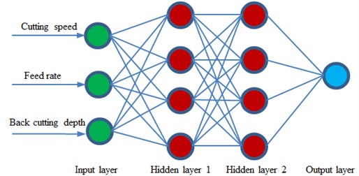
Finite element method was used to study the cutting process and parameters of boring bars. However, computational efficiency would not be very high using the finite element method if the computational model was very complex and computational time under every working condition was relatively long. Therefore, neural network model was used to study the cutting process of boring bars in order to improve computational efficiency and avoid generating the meshes of the model and applying large finite element software. As an emerging information processing technique, artificial neural network [18] has good fault tolerance and adaptability. Many scholars adopted neural network to solve the problem of performance prediction and optimization and achieved satisfactory results [19-21]. In neural network, BP neural network is the most widely used algorithm which is proposed in order to solve the weight coefficient of multi-layer feed-forward neural network [22, 23]. This system adopted the four-layer model structure of BP neural network, namely input layer, double hidden layers and output layer, as shown in Fig. 12. From the analysis of cutting parameters in the third section, it could be seen that cutting speed, feed rate and back cutting depth had an obvious impact on the vibration characteristics of boring bars. Therefore, 3 neurons were set in input layer and 1 neuron was set in output layer. BP neural network adopted the gradient correction method to learn weight and threshold values. When BP neural network structure was basically determined, two important factors affected the learning quality of BP neural network, namely the number of hidden nodes and the size of learning rate factors. An increase in the number of hidden nodes could speed up the decline of error. However, computational amount was increased and the learning time of system would also become long, which reduced the real-time of system. The following formula was adopted to estimate the number of neurons in hidden layers:
wherein, n0 represented the number of neurons in input layer; n1 stood for the number of neurons in hidden layers; n2 referred to the number of neurons in output layer; a meant an arbitrary constant between 0 and 10. High learning rate could speed up the decline of error at the initial stage of learning process. However, learning process could not converge and meet the requirements of system with the deepening of learning process.
Fig. 12Topology structure of BP neural network
However, BP neural network easily gets into local minimum and affects global optimization. Research shows that genetic algorithm is equipped with strong macro search capability and good global optimization performance. The problem of local minimum can be avoided through combining genetic algorithm with BP neural network and applying genetic algorithm to optimize the weights of neural network. However, the training speed of neural network is very slow due to the complex genetic operation such as selection, crossover and mutation of genetic algorithm. Therefore, some scholars proposed to use the quick convergence of particle swarm optimization algorithm to optimize BP neural network [24-26], which could not only obtain the high precision accuracy of optimizing neural network by means of genetic algorithm, but also be quicker than the convergence of optimizing neural network through genetic algorithm. As an evolutionary computation technique, PSO is similar to genetic algorithm, is an optimization tool based on iteration and simulates the herd behavior of creatures like birds and shoal of fish. These creatures search for food by means of cooperation in the process of survival. Every member in the group constantly changes its search mode through learning the experience of itself and other members.
Suppose that M particles constituted a particle swarm in D-dimensional search space, the main computation and derivation formula of PSO algorithm was as follows:
wherein, Vi=(υi1,υi2,…,υiD)referred to the flight speed of the ith particle; Xi=(xi1,xi2,…,xiD) stood for the position of particle in space; Pi=(pi1,pi2,…,piD) represented the historical optimum position of the ith particle in space; Pg=(pg1,pg2,…,pgD) meant the historical optimum position of the whole swarm in space; c1 and c2 stood for acceleration coefficients and usually took 2.0 as their value; r1 and r2 were a random number between [0, 1]; u was inertia weight.
Fig. 13Process of PSO-BP neural network
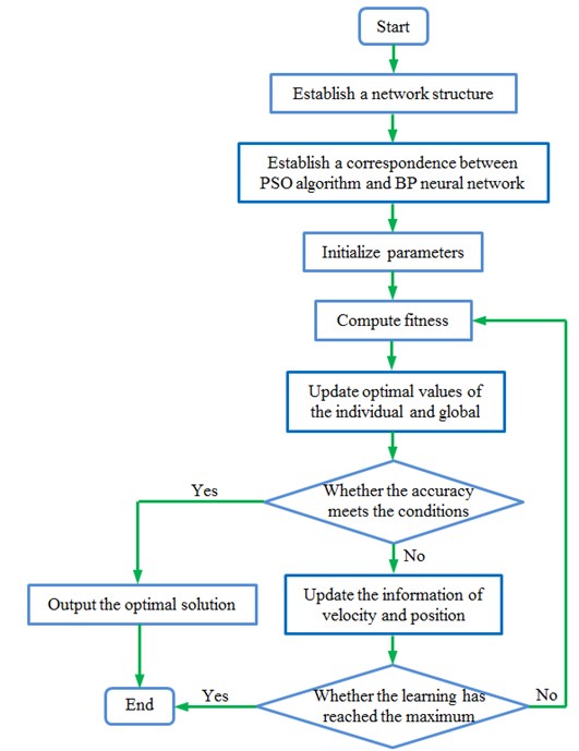
Aimed at the deficiencies of standard BP network, this paper used PSO algorithm to optimize BP neural network, took the weight and threshold values of BP neural network as particles, and completed systematic training process through the mutual learning of particles. The change of weight value was:
wherein, Wij(p) stood for the individual optimal value of corresponding particles; Wij(g) represented the global optimum value of the whole network. Below was the training process of network:
(1) Initialize the parameters of PSO algorithm: Determine the initial weight ustart and end weight uend, learning acceleration coefficients c1and c2as well as the initial position of the particle swarm according to the characteristics of BP neural network.
(2) PSO algorithm is corresponding to BP network: Establish a D-dimensional vector which represents a particle in PSO algorithm and contains the weight and threshold values of hidden layers and output layer in BP network.
(3) Compute the fitness of particles: Establish fitness function to measure whether the position of particles is good and use error function in BP network as fitness function.
(4) Update individual optimal value and global optimum value: Compare the fitness function values of every particle at the time of t-1 and t and upgrade the individual optimal value of corresponding particles if the fitness of particles at the time of t is better, similarly compare the fitness function values of the swarm at the time of t-1 and t and upgrade the global optimum value of the swarm if the fitness of the swarm at the time of t is better.
(5) Update the position and speed of particles: Compute the position and speed of swarms according to Eq. (2) to Eq. (4) and update weight and threshold values of all layers.
Fig. 14Iteration processes of two kinds of neural networks
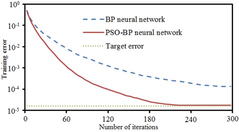
Fig. 15Training and prediction results of PSO-BP neural network
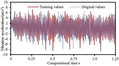
a) Training process
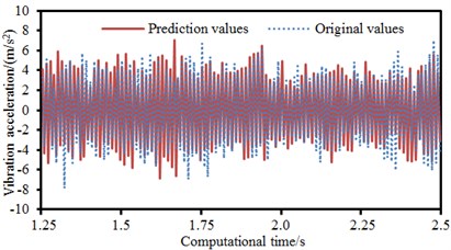
b) Prediction results
Aimed at the description of PSO-BP neural network, the process of algorithm could be obtained, as shown in Fig. 13. The data of time-domain vibration acceleration of boring bars cutting was classified into two parts, including training data and verification. Traditional BP neural network and PSO-BP neural network were used to predict the cutting process of boring bars. The result was shown in Fig. 14. Target error was set as 0.00002. When the iteration number of BP neural network was 300, the target error could not be converged. The iterative error was 0.00015 which was far more than target error. When the iteration number of PSO-BP neural network was 215, iterative error was converged to the set target error. Therefore, predicting the cutting process of boring bars based on PSO-BP neural network had an obvious advantage. Fig. 15 presented the training and prediction results of PSO-BP neural network in predicting the cutting process of boring bars. It could be seen that training and prediction results were basically consistent with experimental results. It indicated that the prediction model in this paper was effective.
5. Conclusions
This paper studied the impact of cutting parameters of boring bars on cutting process based on finite element and PSO-BP neural network model and obtained the following conclusions:
1) Boring bars had high constrained modal frequencies. Modal frequencies of the second and third orders presented obvious flexural vibration. Vibration was very serious at the head of boring bars. Modal frequencies of constrained damping boring bars were obviously more than those of common boring bars. Large modal frequencies could effectively avoid structural resonance in low-frequency and had an obvious advantage in improving anti-vibration performance of boring bars.
2) The time-domain vibration acceleration of constrained damping boring bars was obviously less than that of common boring bars. The absolute value of the maximum vibration acceleration of common boring bars was 13.1 m/s2. The absolute value of the maximum vibration acceleration of constrained damping boring bars was 9.1 m/s2. The maximum vibration acceleration decreased by 30.5 %. In addition, the vibration acceleration of constrained damping boring bars had small peak values. The maximum vibration displacement of common boring bars was 5.2 mm and corresponding frequency was 201 Hz. The maximum vibration displacement of constrained damping boring bars was 2.3 mm and corresponding frequency was 235 Hz. The maximum vibration displacement of boring bars resulted from the resonance caused by the natural frequency of structure. When the analyzed frequency was lower than the frequency of the maximum vibration displacement, the displacement spectrum of common boring bars had more peak values. Thus, it was clear that constrained damping boring bars had an obvious advantage in improving vibration characteristics.
3) Experiment and numerical simulation were basically the same in change trend in the aspect of time-domain vibration acceleration and only peak frequencies were different. The amplitude and corresponding frequency of experiment and numerical simulation were the same in frequency-domain vibration displacement. It showed that the numerical computation model for the machining of boring bars was effective in time-frequency domains.
4) The impact of cutting speed, feed rate and back cutting depth on vibration characteristics was studied respectively. Results showed that the vibration of boring bars gradually decreased with the increase of cutting speed and gradually increased with the increase of feed rate and back cutting depth. In addition, the amplitude and frequency of vibration displacement spectrum of boring bars was basically unchanged no matter how cutting parameters changed.
5) Traditional BP neural network and PSO-BP neural network were respectively used to predict the cutting process of boring bars. When the iteration number of BP neural network was 300, iterative error was 0.00015 which was far more than the set target error. When the iteration number of PSO-BP neural network was 215, iterative error was converged to the set target error. Therefore, PSO-BP neural network had an obvious advantage in predicting the cutting process of boring bars. In addition, the prediction and experimental results of PSO-BP neural network were basically the same, which showed that the neural network model in this paper was effective.
References
-
Liu L. J., Liu X. L., Xu C. Y. Vibration control review of damping boring bar. Journal of Harbin University of Science and Technology, Vol. 19, Issue 2, 2014, p. 12-18.
-
Wang M., Ou B. X., Zan T., et al. Summary of boring bar chatter control technology. Journal of Beijing University of Technology, Vol. 37, Issue 8, 2011, p. 1143-1147.
-
Matsubara A., Maeda M., Yamaji I. Vibration suppression of boring bar by piezoelectric actuators and LR circuit. CIRP Annals-Manufacturing Technology, Vol. 63, Issue 1, 2014, p. 373-376.
-
Kong T. R., Mei D. Q., Chen Z. C. Research on mechanism of cutting chatter suppression based on magnetorheological intelligent boring bar. Journal of Zhejiang University (Engineering Science), Vol. 42, Issue 6, 2008, p. 1005-1009.
-
Akesson H., Smirnova T., Claesson I., et al. On the development of a simple and robust active control system for boring bar vibration in industry. International Journal of Acoustics and Vibration, Vol. 12, Issue 4, 2007, p. 139-152.
-
Hahn R. S. Design of Lanchester damper for elimination of metal-cutting chatter. Transactions of ASME, Vol. 73, Issue 3, 1951, p. 201-213.
-
Ema S., Marui E. Suppression of chatter vibration of boring tools using impact dampers. International Journal of Machine Tools and Manufacture, Vol. 40, Issue 8, 2000, p. 1141-1156.
-
Yan J. X., Ou B. X. Chatter depression of boring rod based on friction energy dissipation. China Mechanical Engineering, Vol. 26, Issue 16, 2015, p. 2143-2147.
-
Hwang H. Y., Kim J. K. Design and manufacture of a carbon fiber epoxy rotating boring bar. Composite Structure, Vol. 60, Issue 1, 2003, p. 115-124.
-
Houck L., Schmitz T. L., Smith K. S. A tuned holder for increased boring bar dynamic stiffness. Journal of Manufacturing Processes, Vol. 13, Issue 1, 2011, p. 24-29.
-
Qin B. Dynamic Characteristics Analysis and Optimization Design of Damping Boring Bar. Harbin University of Science and Technology, Harbin, 2009.
-
Yang J. M., Zhang Y. C., Wu L. J. Multilayered viscoelastic damping properties of composite structural optimization design. Acta Aeronautica et Astronautica Sinica, Vol. 32, Issue 2, 2011, p. 265-270.
-
Rubio L., Loya J. A., Miguelez M. H. Optimization of passive vibration absorbers to reduce chatter in boring. Mechanical Systems and Signal Processing, Vol. 41, Issue 1, 2013, p. 691-704.
-
Fu Q., Lundin D., Nicolescu C. M. Anti-vibration engineering in internal turning using a carbon nanocomposite damping coating produced by PECVD process. Journal of Materials Engineering and Performance, Vol. 23, Issue 2, 2014, p. 506-517.
-
Khan S. U., Li C. Y., Siddiqui N. A., et al. Vibration damping characteristics of carbon fiber-einforced composites containing multi-walled carbon nanotubes. Composites Science and Technology, Vol. 71, Issue 12, 2011, p. 1486-1494.
-
Saffury J., Altus E. Optimized chatter resistance of viscoelastic turning bars. Journal of Sound and Vibration, Vol. 324, Issue 1, 2009, p. 26-39.
-
Sortino M., Totis G., Prosperi F. Modeling the dynamic properties of conventional and high-damping boring bars. Mechanical Systems and Signal Processing, Vol. 34, Issue 1, 2013, p. 340-352.
-
Wang T., Gao H., Qiu J. A combined adaptive neural network and nonlinear model predictive control for multirate networked industrial process control. IEEE Transactions on Neural Networks and Learning Systems, Vol. 27, Issue 2, 2016, p. 416-425.
-
Khan J., Wei J. S., Ringner M., et al. Classification and diagnostic prediction of cancers using gene expression profiling and artificial neural networks. Nature Medicine, Vol. 7, Issue 6, 2001, p. 673-679.
-
Shi B., Bai X., Yao C. An end-to-end trainable neural network for image-based sequence recognition and its application to scene text recognition. IEEE Transactions on Pattern Analysis and Machine Intelligence, 2016.
-
Sharma A., Sahoo P. K., Tripathi R. K., et al. Artificial neural network-based prediction of performance and emission characteristics of CI engine using polanga as a biodiesel. International Journal of Ambient Energy, Vol. 37, Issue 6, 2016, p. 559-570.
-
Wang D., Luo H., Grunder O., et al. Multi-step ahead electricity price forecasting using a hybrid model based on two-layer decomposition technique and BP neural network optimized by firefly algorithm. Applied Energy, Vol. 190, 2017, p. 390-407.
-
Yi J., Wang Q., Zhao D., et al. BP neural network prediction-based variable-period sampling approach for networked control systems. Applied Mathematics and Computation, Vol. 185, Issue 2, 2007, p. 976-988.
-
Ping W., Huang Z., Zhang M., et al. Mechanical property prediction of strip model based on PSO-BP neural network. Journal of Iron and Steel Research, International, Vol. 15, Issue 3, 2008, p. 87-91.
-
Wen P., Zhi M., Zhang G., et al. Fault prediction of elevator door system based on PSO-BP neural network. Engineering, Vol. 8, 2016, p. 11-761.
-
Gordan B., Armaghani D. J., Hajihassani M., et al. Prediction of seismic slope stability through combination of particle swarm optimization and neural network. Engineering with Computers, Vol. 32, Issue 1, 2016, p. 85-97.
Cited by
About this article
This paper is written by Xianming Chen, the idea is from Tieliu Wang, translation is completed by Mingming Ding, experiment is conducted by Jing Wang and Jianqing Chen, and language polish and paper submission are completed by Junxia Yan.
