Abstract
In the electrical discharge machine (EDM), the slide carriage system of the axis connects the lathe bed and the ram of the Y axis, its thermal-deformation has a directly effect on machining precision. Based on Solid-works and ANSYS Workbench software to build the finite element model (FEM) of the slide carriage system, the heat generation of the motor on the axis, and the frictional heat of the bearing and guide as the main thermal source, there are two cases: applied and no contact thermal resistance (TCR) as the thermal-structure coupling deformation analysis. Established a model of the natural convection heat transfer coefficient with the temperature-change according to the actual measured the temperature curve of workshop and mathematical logarithm principle. The analysis told us that: in the thermal analysis of precision mechanical equipment, heat source comes from the external environment temperature and motor heat production, at the same time, the contact thermal resistance and the natural convection heat transfer coefficient with the temperature-change for the thermal characteristics of the equipment will make an important influence.
1. Introduction
In order to meet the requirements of precision machining of key parts for aerospace, EDM has been widely used because of its features that overcome the strong by applying soft methods, precision with subtle, shape-lifelike, and high degree of automation [1]. As a precision machine equipment, the error source that affects machining precision mainly comes from thermal-deformation and geometric error. However, with the continuous improvement of manufacturing technology, the proportion of geometric error is smaller than thermal-deformation. Statistical studies show that: in precision machining, the machining error caused by machine tool thermal-deformation occupied the total error’s 40 %-70 % [2].
Based on ANSYS software, Han analyzed the thermal characteristics of the TK6920 ram system told that the uniformity of temperature distribution is a key factor affecting the thermal-deformation of the machine tool [3]. Zhang calculated three directions and the overall thermal-deformation of the ram in the direction of feeding in different positions when they analyzed the thermal structure for the large-scale gantry milling machine spindle pillow [4]. All of the above studies were carried out under the assumption that the contacting-surfaces were completely in contact with each other, and that the external environment and the wall temperature of the components were constant. However, under actual conditions, the contact of the two solid surfaces occurs only at some discrete-points. Theory is that: the actual contact area of two contacting-surfaces does not exceed the nominal contact area of 2 % [5], the heat will produce contact resistance in the transmission process. Zhao pointed out: contact thermal resistance on the transmission of machine heat, isolation and the resulting temperature field and thermal-deformation has a very large impact [6]. In addition, the larger the temperature difference between day and night in the north, the temperature of the machine tool processing accuracy will also have an impact. Cao Yi established thermal bending model of the guide rail based on the temperature difference along the bed’s height [7]. B Tan studied the impact of external heat on the accuracy of the machine found whether the machine works, the change of the ambient temperature will cause the machine structure of internal heat flow, resulting machine thermal-deformation [8]. Therefore, in the thermal analysis of machine tools, it is necessary to consider the contact resistance and the external ambient temperature changes.
In this paper, EDM’s X-Slide system is taken as the object of study, and its 3D solid model is established with Solid-works software. In the study of convective heat transfer coefficient, the natural convection heat transfer coefficient and the ambient temperature as a function of the relationship. The finite element model was analyzed by using the ANSYS Workbench software to analyze the thermal-structural coupling deformation under the contact thermal resistance and the non-contact thermal resistance. In addition, the curve of the temperature and thermal-deformation of a point at the end of the slide was established with the ambient temperature. The results provide a basis for establishing a more precise EDM thermal-deformation model.
2. Contact thermal resistance calculation
Microscopically, any part of the surface randomly distributing with small convex peaks, when the two parts contact each other, the contacting-surfaces will not completely contact. Compared with the thermal-conductivity of contact with the metal, the thermal-conductivity of medium in the gap is very small, the heat flow through the contact-surfaces by the heat flow generated by the phenomenon of contraction, resulting in contact thermal resistance, the temperature drops between the contact-surfaces, shown in Fig. 1.
Fig. 1The cutaway view of the X to the slide carriage system and the actual situation of contact-surfaces.
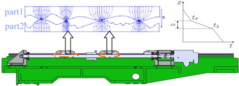
Due to the temperature-rise of the numerical control electric spark machine tool is small, thus ignore the gap between the radiation heat transfer on the basis of heat transfer between the contact-surfaces was thought to be mainly by mutual contact of micro convex peak and heat conduction of medium, and assume the conduction path non-interference in each other. Accordingly, the formula was used by Shlykov puts forward to calculate the contact thermal resistance the [9]:
where is contact area; is contact heat transfer coefficient; is the thermal-conductivity of medium between gaps; , are two root mean square roughness of the contact-surfaces; , are two contact material thermal-conductivity; is contact-surfaces pressure; is the two contacting-surfaces of the surface hardness of the softness; , are the contact number of square root for roughness on the surface. Among them, when the 8.5 μm, 1; When 2.9 μm 8.5 μm, ; When 2.9 μm, . . is found in the document [10].
The heat transfer process and route of -skateboard system can be shown as the simplified model in Fig. 2.
Fig. 2Heat transfer model and thermal resistance notation of the slide carriage system of the X

The factors affecting the contact thermal resistance mainly includes: the surface roughness, temperature, contact pressure and contact materials. As the EDM is not affected by cutting force in processing, the pressure of the slider in the -slide carriage system is 0.67 MPa. In addition, assuming constant temperature and isotropic material, using the Eq. (1) to calculate the thermal contact conductance coefficient (TCC) related to the TCR in the Fig. 2, its value Shown in Table 1.
Table 1The contact heat transfer coefficient between the contact-surfaces
Contact position | |||||
The value of TCC (W/ m2·°C) | 3146.83 | 6963.25 | 5838.26 | 5635.41 | 5840.32 |
3. The establishment of finite element model
As the modeling function of the ANSYS Workbench software is weak, and the good entity model can improve the accuracy of the analysis and calculation, so the Solidworks software is adopted to establish the entity model of the -slide carriage system, then through the initial graphics exchange specification (IGES) imported into ANSYS Workbench software. The FEM of -slip plate system has been shown in Fig. 3, the model contains 282780 nodes, 159282 units.
4. Determination of heat source and boundary conditions
4.1. Analysis and calculation of the heat source
On the EDM machine, the heat source mainly comes from the -motor, bearing or guide friction heat when the main shaft moves along the .
(1) -motor heat. Practical work, the -motor’s power is 3 . For the convenience of calculation, there are some assumptions: the power of motor loss is converted into heat, which ignore the energy loss. Therefore, the motor generates the heat () and heat flux are expressed respectively as:
where is the motor input power; is motor efficiency; is volume of the -motor.
(2) Bearing friction heat. The friction heat in bearing will be produced when -motor driven ball screw, and impacted by the friction torque. In Palmgren’s opinion, friction torque of the bearing is mainly composed of load friction torque () and the lubricant viscosity friction torque (). According to friction torque measurement result of the open bearing, Palmgren proposed the approximate algorithm of the bearing friction torque. Hence, the friction heat () is expressed as:
where is the bearing rotating speed; is bearing friction torque; is a constant related to the bearing type; is bearing diameter; is kinematic viscosity of the lubricant under the working temperature; is constant related with the bearing types and load; is load of calculating.
Based on the above research, the heat flux can be determined by the formula:
where is bearing’s volume.
(3) Guide vice friction heat. When the relative occur between slip sliding block and rail, the friction heat and heat flux are:
where is the kinetic friction factor; is the load on the contact surface; is acceleration of gravity; 4.2 J/cal; is sliding speed; is rail friction area.
Therefore, the calculation results of the heat and heat flux are shown in Table 2.
Table 2The heat and heat flux of the thermal source
Motor | Bearings | Guide | |
Heat | 450 W | 40.51 W | 28.03 W |
Heat flux | 42300 W/m3 | 624000 W/m3 | 215.62 W/m2 |
Fig. 3The finite element model
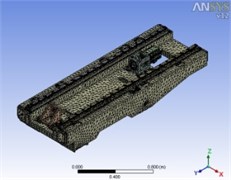
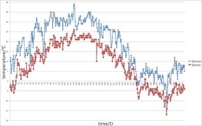
Fig. 4Workshop temperature change curve over time
4.2. The determination of boundary conditions
The -slip board system’s heat transfer is natural convection with the external environment; there will be a forced convective heat transfer when ball screw rotates. Convective heat transfer coefficient calculation formula is:
where is Nusselt number; is thermal-conductivity; is feature sizes.
For the natural convection heat transfer, the equation of Nusselt number is:
where , are constant, determined by literature [11]; is Grashof numeral; is Prandtl number; is body expansion coefficient; is air movement viscosity; is the temperature difference between environment temperature and wall of parts.
According to the actual measurement results, temperature changes of the workshop were draw, shown in Fig. 4. Obviously, the natural convection heat transfer coefficient is not constant, but the nonlinear function of temperature.
Assuming the initial temperature of workshop is 20 °C, 21.4×10⁻⁶m2/s, 15.06×10⁻⁶m2/s, 0.703; If 40 °C, 24.3×10⁻⁶m2/s, 16.96×10⁻⁶m2/s, 0.699. Combined and , and on both sides of the logarithmic:
When the environment temperature is :
As a result, there is a relationship of index between the natural convection heat transfer coefficient and temperature.
For forced convection heat transfer, when the speed of the ball screw pair is 600 r/min, is a constant, the Reynolds number is below 5000 for the laminar flow, so:
According to the Eqs. (6-10), natural convection heat transfer coefficient expression is 7.73×(-20)0.25 W/(m2·K). when the temperature is 20 and 32 °C, the forced convection heat transfer coefficients were 31.2 W/(m2·K), 36.24 W/(m2·K).
5. Thermal-structure coupling deformation analysis
The heat source and boundary conditions are applied to the finite element model of -slip plate system, there will be four groups research on the basis of steady state thermal analysis: consider or without contact thermal resistance when the temperature is 20 °C and 32 °C. Figs. 5-8 had shown the distribution of the temperature field and thermal-deformation.
Fig. 5The temperature field and thermal-deformation of 20 °C without TCR
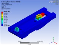
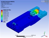
Fig. 6The temperature field and thermal-deformation of 20 °C with TCR
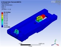
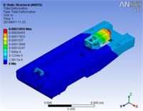
Fig. 7The temperature field and thermal-deformation of 32 °C without TCR
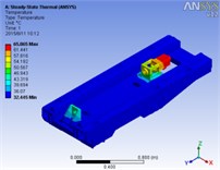
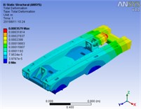
Fig. 8The temperature field and thermal-deformation of 32 °C with TCR
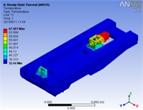
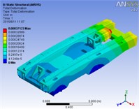
We found that the highest temperature and the maximum thermal-deformation occurred on the -motor, the highest temperature of the -slip plate in contact with the motor cabinet, and the biggest thermal-deformation occurred in the tail of -slip board. The friction heat caused by guide generates little impact on the distribution of temperature field by observing, so it can be neglected in the later system analysis; besides, the external environment temperature on the temperature field of the -slip board, can be used as heat source.
6. Conclusions
The thermal-deformation -slide system has a direct impact to the machining accuracy of EDM. Based on the FEM, we obtained some conclusions as follow:
The contact thermal resistance impacts thermal characteristics of the -slip plate system, it is closer to actual working condition when considering the TCR. The highest temperature and the maximum thermal-deformation of -slip board system occurred on the -motor, the highest temperature of -slip plate in contact with the motor city, and the biggest thermal-deformation occurred in the tail end of the -slide carriage. The environment temperature changes impact on natural convection heat transfer coefficient, the exponential relationship between the size and temperature.
References
-
Cao Fengguo Special Processing Manual. China Machine Press, Beijing, 2010.
-
Ramesh R. EIT or Compensation in machine tools a review. Part 1: Thermal errors. International Journal of Machine Tools and manufacture, Vol. 40, 2000, p. 1257-1284.
-
Han Jiang, Ang Jinfeng, Xia Lian, et al. Thermal characteristics analysis of the ram system of TK6920 heavy-duty CNC floor-type boring and milling machine tools based on ANSYS. Combined Machine Tool and Automatic Machining Technology, Vol. 9, 2012, p. 13-15.
-
Zhang Kuikui, Huang Meifa, Wu Wei, et al. Thermal structure analysis of spindle ram for large-scale milling planer. Combined Machine Tool and Automatic Machining Technology, Vol. 2, 2015, p. 42-46.
-
Yovanovich M. M., Marotta E. E. Thermal Spreading and Contact Resistances. Wiley, New Jersey, 2003, p. 261-395.
-
Zhao Honglin, Huang Meiyu, Sheng Bohao, et al. Thermal model research contains junction surface structure. Manufacturing Technology and Machine Tool, Vol. 7, 1999, p. 10-11.
-
Cao Yi The influence of environment temperature on the precision machine tool guide way. Precise Manufacturing and Automation, Vol. 4, 1983, p. 57-60.
-
Tan B., Mao X., Liu H., et al. A thermal error model for large machine tools that considers environmental thermal hysteresis effects. International Journal of Machine Tools and Manufacture, Vols. 82-83, 2014, p. 11-12.
-
Shlykov Y. L. Calculating thermal contact resistance of machined metal surfaces. Teploenergetika, Vol. 10, 1965, p. 79-83.
-
Kraus A. D., Bar-Cohen A. Thermal Analysis and Control of Electronic Equipment. Hemisphere Publishing Corp., Washington, DC, 1983.
-
Xu Guoliang, Wang Xiaomo, Wu Tianhua, et al. The Engineering Heat Transfer. China Power Press, Beijing, 2005.
About this article
The research is supported by Beijing Municipal Science and Technology Commission (Name: The Key Technologies of Harmonic Reducer for Robotic Joint and Its Typical Applications), Large Scientific Research Promotion Program of Beijing University of Technology, This work was supported by Beijing Natural Science Foundation (No. 3162003), Jing-Hua Talents Project of Beijing University of Technology, National Natural Science Foundation (No. 51575009) and Graduate Students of Science and Technology Fund of Beijing University of Technology.
