Abstract
Labyrinth seal is a key component for the safe and reliable operation of a turbine unit. This paper sets up a three-dimensional numerical model of a labyrinth seal with a tilting rotor based on a compressor eye seal which was studied by Computational Fluid Dynamics method and a test labyrinth seal. The influence of the tilting rotor on the static and dynamic characteristics of labyrinth seals was investigated. Numerical results demonstrated a good agreement with the published article. Both the radial and tangential fluid-induced forces show an obvious increase when the rotor is in tilting conditions. From an efficiency viewpoint, a bigger tilt angle of the rotor is desirable. And eccentricity existence is not beneficial to the seal performance. The results based on the test seal show the whirl frequency ratio increases with the increasing eccentricity ratio. In case of tilting conditions (δ= 0.05 mm, θ= 0.8 deg), the whirl frequency ratio decreases with the increasing rotational speed. The higher rotational speed will be beneficial to the stability improvement when the rotor is in tilting conditions. The whirl frequency ratio also shows a decrease with the increasing inlet pressure. The higher inlet pressure tends to improve the stability when the rotor is in tilting conditions. All the stiffness coefficients and damping coefficients increase as the tilt angle increases. The whirl frequency ratio also shows an increase with the increasing tilt angle. The tilting rotor tends to reduce the stability when the rotor is in eccentric conditions.
1. Introduction
Labyrinth seal is widely applied in turbomachineries to minimize the fluid leakage and improve the unit efficiency. With the improvement of turbine operating parameters, the system instability problem resulting from labyrinth seals, which is usually called as fluid-induced vibration, becomes more and more serious. A lot of researches on the static and dynamic characteristics of labyrinth seals, in which the central axis of the rotating rotor is generally parallel to that of the static components, have been studied in recent years. However, the rotor is always tilting with a certain amount in actual operation conditions. Influence of the tilting rotor on the static and dynamic characteristics of labyrinth seals should be investigated further.
A lot of factors can influence the static and dynamic characteristics of a labyrinth seal, such as the seal shape (straight, tapered, or stepped), the tooth location (on stator, on rotor, or on both with tooth interlocking), and the number of teeth. Since the 1980s, many researchers have studied the labyrinth seal performance. A minimum leakage is the original and primary objective by optimizing geometric conditions at different boundary conditions. Denecke [1] presented an experimental investigation on the influence of stator rub-groove, which has a great influence on the seal leakage characteristic and impairs the overall engine efficiency. Shimada [2] clarified the causes that lead to the significant decrease of the leakage rate by rotation under the condition of an extremely low static pressure difference. Picardo [3] presented the rotor-dynamic and leakage coefficients for a labyrinth seal that was tested at a supply pressure of 70 bar and speeds up to 20, 200 rpm. Tests were conducted at different clearances, pressure ratios and preswirl ratios. Comparisons were also made between rotor-dynamic coefficients of labyrinth and hole-pattern seals. Gamal [4] examined the effects of varying blade profile and blade thickness on the leakage through see-through labyrinth seals. Gamal [5] reformulated the problem of leakage through the seal to include stationary and rotating conditions, as well as to present and clarify the influence of shape, size and aspect ratio on the performance. Results showed that shaft rotation had a little effect on the leakage from the grooved shaft and grooved casing seals while it made a considerable improvement of the performance of the up-the-step seal. On the other hand, shaft rotation had an adverse effect on the performance of the down-the-step seal. Some improvement was obtained at low leakage rates when the smaller clearance was situated at the entrance of the grooved shaft seal. The effect of unequal clearance sizes for the grooved casing and up-the-step seals was quite small.
With the improvement of turbine operating parameters, the system instability problem due to labyrinth seals attracts more and more attentions. Lots of researches were carried out to clarify its inherent mechanism, influence factors, solution methods. Childs and Scharrer [6, 7] established a two-control-volume model for compressible flow in the labyrinth gas seal. Experimental and theoretical results were carried out for a comparison. Rajakumar [8] presented experimentally-measured seal cavity pressure distributions for different rotor eccentricities. The eccentricity of the rotor center relative to the seal center introduced asymmetry in the seal clearance flow causing the circumferential pressure variation in seal cavities. Resultant seal forces obtained by integrating the circumferential pressures over the rotor surface were presented as a function of rotor eccentricity. Yucel [9] investigated the gas flow in straight-through labyrinth seal and its effect on the stability of the rotor. Kwanka [10] used a new, easy-to-handle identification procedure about the stability behavior of a flexible rotor to determine the dynamic coefficients. Song [11] presented a new model to predict flow response for a shrouded axial turbine stage. It was found that the flow migrated azimuthally away and the pressure reached its peak near the maximum seal clearance in turbines with the eccentric shrouded rotor. Both torque asymmetry and pressure asymmetry contribute to the positive cross force and thus promote a forward whirl, or rotor-dynamic instability. Wang [12] presented a mathematical model of calculating rotor-dynamic coefficients associated with leakage steam flow through labyrinth seals. Rotor-dynamic coefficients associated with the leakage steam flow through a straight-through labyrinth seal were calculated at the same condition and compared with that of the air flow. Liu [13] performed a comparative study on the influence of the aerodynamic force induced by the leakage flow through the labyrinth seal on rotordynamics by using numerical calculations and experimental measurements. Pugachev [14] presented an analysis of the experimental and theoretical methods used to study rotor-dynamic characteristics of a short staggered labyrinth gas seal. The effects of pressure differential, inlet swirl, shaft rotational speed, shaft eccentricity, and inflow cavity on seal stiffness and damping were presented. Guo and Kirk [15] simulated the 3D flow in a stepped and tooth interlocking labyrinth seal by solving the Reynolds-averaged Navier-Stokes (RANS) equations in the commercial software ANSYS-CFX. The influence of preswirl on the rotor-dynamic properties of the seal was investigated. Hirano [16] describes the evaluation of unstable vibration caused by the seal force, which is known as “Steam Whirl” for steam turbines. The stability of a steam turbine was evaluated by the complex eigenvalue analysis of the rotor-seal-bearing system.
Besides above mentioned geometric conditions, boundary conditions, etc., the actual operation conditions also influence the static and dynamic characteristics of labyrinth seals. Rhode [17] presented some of the first measurements and visualization movies for stepped labyrinths to give an enhanced understanding of the effect of rounded labyrinth teeth tips and worn abradable lands. Kwanka [18] presented experimental and theoretical investigations concerning a long staggered labyrinth gas seal. The influence of the entry swirl, the rotational speed and the pressure difference on the conservative and the nonconservative force were assessed. Schramm [19] described the simulated annealing optimization method to minimize the leakage through a three-finned, stepped labyrinth. The step position and the step height were chosen to be variable. Xi [20] investigated the influence of the rotor axial shifting on the leakage rate as well as rotor-dynamic forces in high-low labyrinth seals over a range of seal clearances and inlet swirl velocities. It was also found that a less destabilizing effect arose from the rotor axial shifting in the leakage flow direction, whereas a more destabilizing effect arose from shifting against the leakage flow direction.
It would be interesting to examine the influence of the rotor tilting in actual operation conditions on the leakage performance and the dynamic characteristics of labyrinth seals. This paper established computational models of two kinds of labyrinth seals. The aim is to investigate the influence of the tilting rotor on the static and dynamic characteristics of labyrinth seals. Different models with varying boundary conditions, such as eccentricity ratio, rotational speeds, inlet pressure, tilt angle, were analyzed.
2. Numerical model
In this paper, two models were employed to verify and analyze the inherent characteristics of the fluid-induced vibration for labyrinth seals. The first model is based on Hirano’s compressor eye seal [21]. The second model is based on our previous experimental labyrinth seal [22].
The two-dimensional geometry of Hirano’s compressor eye seal is shown as Fig. 1. The labyrinth seal consists of five teeth totally. The rotor central axis has a deflection with the displacement δ0 (0, 0.0292 mm) and tilt angle θ0(0, 0.25, 0.5, 0.75, 1.0, 1.25, 1.5 deg). The detailed boundary conditions can be found in reference [21].
Fig. 2 gives a two-dimensional diagram of the test labyrinth seal in the meridian plane. There are four teeth totally. Also, the rotor central axis has a deflection with the displacement δ and tilt angle θ. The rotor eccentric direction is along the negative y-axis direction. Zero degree is defined along the positive direction of the z-axis. Table 1 gives the detailed boundary conditions.
Fig. 1Two-dimensional structure diagram of Hirano’s compressor eye seal
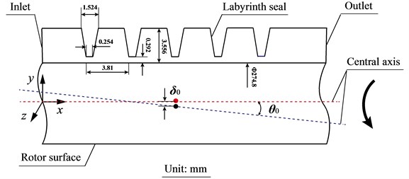
Fig. 2Two-dimensional structure diagram of experimental labyrinth seal
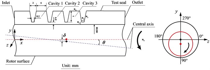
Table 1Boundary conditions for experimental labyrinth seal
Rotational speed N / rpm | Inlet pressure Pin / atm | Inlet temperature T / K | Outlet pressure Pout / atm | Tilt angle θ / deg | Eccentricity ratio E | Fluid | Flow |
1500, 3000, 4500, 6000, 7500, 9000 | 1.2, 1.5, 1.75, 2.0, 2.3 | 300 | 1.0 | 0.5, 0.8, 1.0, 1.2, 1.4 | 0, 0.1, 0.15, 0.2, 0.3, 0.4 | Air (ideal gas) | Compressible, Turbulent, RNG k-ε |
Table 2Mesh distribution
Location | n1 | n2 | n3 | n4 | n5 |
Node number | 10 | 15 | 50 | 50 | 48 |
The CFD has been employed more and more widely in recent years because it has the capacity to solve a large number of problems with complex design configurations and parameters [23-30]. In the paper, the Reynolds-Averaged-Navier-Stokes (RANS) analysis of the flow field in labyrinth seals is performed by ANSYS FLUENT 15.0. FLUENT solves the equations for the conservation of mass, momentum, and energy according to the dependent variables. The three-dimensional computational grid for the labyrinth seal is generated by Gambit 2.4.6. A complete asymmetric 360 degree CFD model is established, and the model takes the effect of the rotor eccentricity and rotor tilt into account. Fig. 3 shows a three-dimensional model.
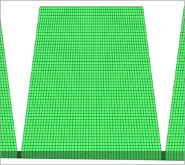
A mesh density test is performed to investigate the effect of mesh density on the flow characteristics. As shown in Fig. 2, the process includes incremental adjustments to the grid size (n1, n2, n3, n4, n5) until the leakage flowrate and fluid-induced force results keep independent. In the end, the resulting computational model comprises of about 1 120 608 nodes. The node number of each segment is shown in Table 2, and n5 denotes the node number in the circumferential direction. Near wall values are checked for all cases to make sure that the mesh is appropriate for the application of the wall function. Values of the dimensionless wall distance (y+) are about between 31 and 65, which is acceptable for the wall function in this paper. Fig. 4 shows the global and local mesh distribution. For the boundary condition with great variations, the adaptive mesh is employed to ensure the proper y+.
Table 1 gives the boundary conditions defined for the test seal. An adiabatic boundary condition is applied for the stationary wall and the rotational rotor surface, and all walls in the model have a no slip boundary condition. The calculation assumes the fluid to be an ideal gas (air) and the entire flow to be turbulent. The RNG k-ε model is used for the turbulent compressible flow. The momentum equations, the continuity equation, and the turbulence model equations are solved by the SIMPLE pressure-velocity coupling algorithm. Second-order upwind discretization is employed for the momentum and energy equations, and the pressure is discretized with the second-order scheme. The fluid-induced force can be obtained by integrating the uneven pressure acting on the rotor surface.
Fig. 3Three dimensional model of experimental labyrinth seal
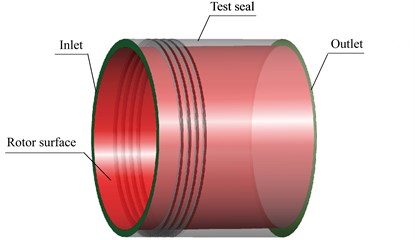
Fig. 4Mesh distribution for experimental labyrinth seal
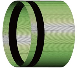
a) Global mesh density
b) Local mesh density
The rotating frame of reference is applied at a specific rotational speed with various whirl speeds to get the dynamic characteristic coefficients. For the present model, the effect of inertia can be neglected. And the dynamic coefficients can be derived as:
where K, k denote the direct and cross-coupled stiffness coefficients, C, c denote the direct and cross-coupled damping coefficients, Fr, Ft denote the fluid induced forces in the radial and tangential directions, Ω denotes the whirl speed, and δ denotes the eccentricity.
Since a direct comparison of the coefficients, such as cross-coupled stiffness and direct damping, does not show any clear stability advantage/disadvantage or the overall effect of a change in different structural dimensions and boundary conditions, the non-dimensional whirl frequency ratio has been frequently adopted by many researches to describe the system stability due to the labyrinth seal [6, 31]. It is defined as:
where ω is the angular rotor velocity, ω=2πN/60 (rad/s), N is the rotational rotor speed.
Whirl frequency ratio is the ratio of the destabilizing influence of the cross-coupled stiffness and the stabilizing influence of direct damping. From a stability viewpoint, a minimum whirl ratio is desirable.
3. Results and discussion
3.1. Influence of tilting rotor on the fluid-induced force and leakage characteristics of Hirano’s seal
Hirano’s compressor eye seal was firstly performed to analyze the influence of tilting rotor on the static and dynamic characteristics. On the other side, it was employed to verify the present numerical method used in this paper.
Fig. 5 shows the fluid-induced force varying with the increasing tilt angle for different rotational speeds in case of E= 0 (δ0=0). For the radial fluid-induced force, it increases linearly as the tilt angle increases for all rotational speeds. Rotational speeds have little effect on the radial fluid-induced force. In the tangential direction, the fluid-induced force shows different increasing tendencies. The fluid-induced force is zero when the rotational speed is zero. While the rate of increment becomes more and more significant as the rotational speed increases. This is caused by a high speed on the rotor surface due to the increasing rotational speed.
Fig. 5Fluid-induced force changes with increasing tilt angle (E= 0)
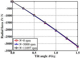
a) Radial fluid-induced forces vs. tilt angles
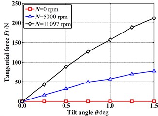
b) Tangential fluid-induced forces vs. tilt angles
Fig. 6Leakage flowrate changes with increasing tilt angle (E= 0)
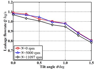
Fig. 6 shows the change of the leakage flowrate as the tilt angle increases for different rotational speeds in case of E=0 (δ0=0 mm). The leakage flowrate decreases with the increasing tilt angle for all rotational speeds. With the increasing rotational speed, the leakage flowrate shows a slight decrease. From an efficiency viewpoint, a bigger tilt angle of the rotor is desirable.
Fig. 7 and Fig. 8 shows the fluid-induced force and leakage flowrate varying with the increasing tilt angle for different rotational speeds in case of E=0.1 (δ0=0.0292 mm). The results demonstrate a good agreement with the Hirano’s published paper. The results show almost the same tendency with that in case of E=0. However, both the fluid-induced force and leakage flowrate in case of E=0.1 (δ0=0.0292 mm) become greater than that in case of E=0. It means the eccentricity existence is not beneficial to the seal performance.
Fig. 7Fluid-induced force changes with increasing tilt angle (E= 0.1)
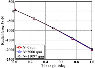
a) Radial fluid-induced forces vs. tilt angles
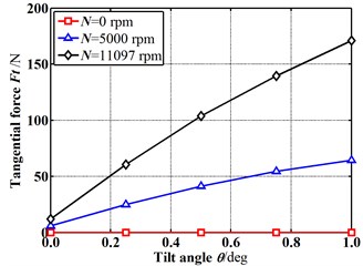
b) Tangential fluid-induced forces vs. tilt angles
Fig. 8Mass flowrate changes with increasing tilt angle (E= 0.1)
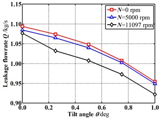
It was well known that the magnitude of fluid-induce forces cannot reflect the inherent stability of the labyrinth seal comprehensively. To analyze the combined influence of rotor eccentricity and tilt angle on the static and dynamic characteristics of labyrinth seals further, the dynamic parameters, such as stiffness coefficient, damping coefficient, whirl frequency ratio, etc., are performed in next sections based on our previous test seal. Also, the rotational speed and inlet pressure are analyzed.
3.2. Influence of eccentricity ratio on dynamic characteristics of test seal
Our previous test seal was further performed to analyze the influence of the tilting rotor on the dynamic characteristics for labyrinth seals.
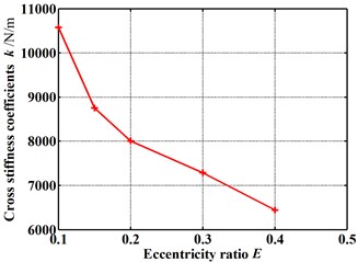
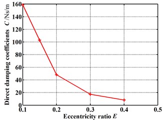
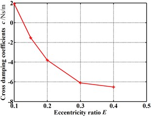
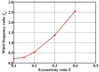
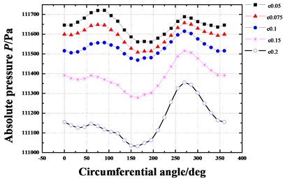
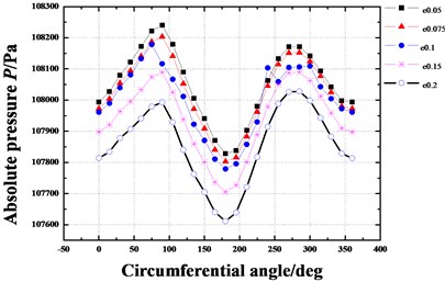
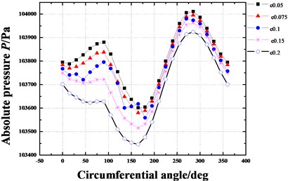
Fig. 9 gives the dynamic coefficients varying with the increasing eccentricity ratio. The direct and cross-coupled stiffness coefficient as well as direct damping coefficient become smaller and smaller as the eccentricity ratio increases. While the absolute value of cross-coupled damping coefficient increases with the increasing eccentricity ratio. It is difficult to see the overall effect of the varying eccentricity ratio. While the whirl frequency ratio shows an increase with the increasing eccentricity ratio, as shown in Fig. 10. It denotes a minor eccentricity of the rotor is desirable. Fig. 11 shows the pressure distribution in the circumferential direction of seal cavities for different eccentricity ratios. The pressure fluctuation changes more and more drastically as the eccentricity ratio increases, especially for cavity 1 and cavity 3.
Fig. 9Dynamic coefficients change with increasing eccentricity ratio: (Pin= 1.2 atm, N= 3000 rpm, θ= 0.8 deg)
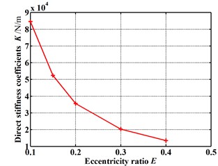
a) Direct stiffness coefficients
b) Cross-coupled stiffness coefficients
c) Direct damping coefficients
d) Cross-coupled damping coefficients
Fig. 10Whirl frequency ratio changes with increasing eccentricity ratio (Pin= 1.2 atm, N= 3000 rpm, θ= 0.8 deg)
3.3. Influence of rotational speeds on dynamic characteristics of test seal
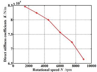
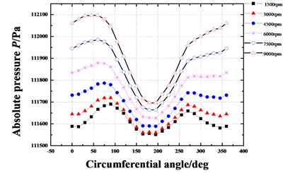
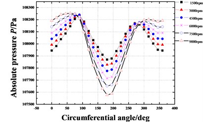
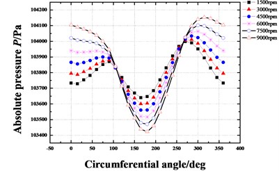
Fig. 12 gives the dynamic coefficients varying with increasing rotational speeds when the rotor is in the tilting condition (δ=0.05 mm, θ=0.8 deg). Except for the direct stiffness coefficient, both the stiffness coefficient and damping coefficient increase as the rotational speed increases. As shown in Fig. 13, however the whirl frequency ratio shows a decrease with the increasing rotational speed. It means the higher rotational speed will be beneficial to the stability improvement when the rotor is in tilting conditions. This conclusion is contrary to the results of previous publications in which the rotor tilt is not taken into account. Fig. 14 shows the pressure distribution in the circumferential direction of seal cavities for different rotational speeds. Although the pressure fluctuation becomes more significant with increasing rotational speeds, the peak pressure shifts at the same time. As the rotational speed increases, the angle of maximum pressure changes from about 270° to 315°. The fluid induced force tends to weaken a forward whirling motion of the rotor. As a result, the tilting rotor has a better stability performance for higher rotational speeds.
Fig. 11Pressure distribution in circumferential direction of seal cavities for different eccentricity ratios (Pin= 1.2 atm, N= 3000 rpm, θ= 0.8 deg)
a) Cavity 1
b) Cavity 2
c) Cavity 3
Fig. 12Dynamic coefficients change with increasing rotational speed (Pin= 1.2 atm, E= 0.1, θ= 0.8 deg)
a) Direct stiffness coefficients
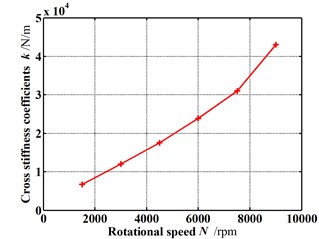
b) Cross-coupled stiffness coefficients
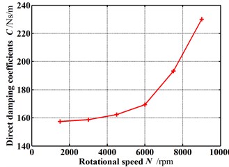
c) Direct damping coefficients
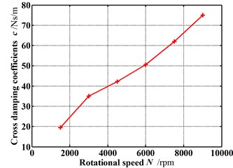
d) Cross-coupled damping coefficients
Fig. 13Whirl frequency ratio changes with increasing rotational speed (Pin= 1.2 atm, E= 0.1, θ= 0.8 deg)
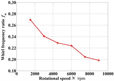
Fig. 14Pressure distribution in circumferential direction of seal cavities for different rotational speeds (Pin= 1.2 atm, E= 0.1, θ= 0.8 deg)
a) Cavity 1
b) Cavity 2
c) Cavity 3
3.4. Influence of inlet pressure on dynamic characteristics of test seal
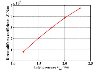
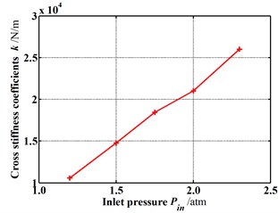
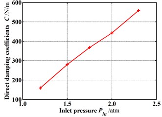
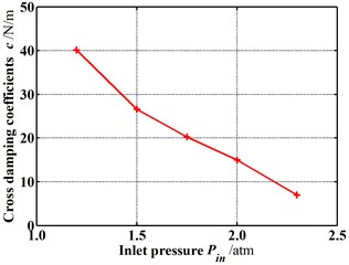
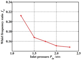
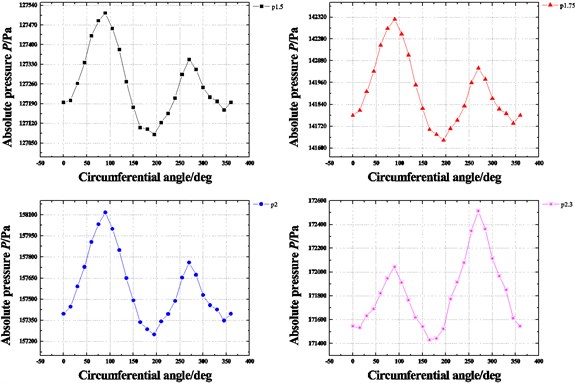
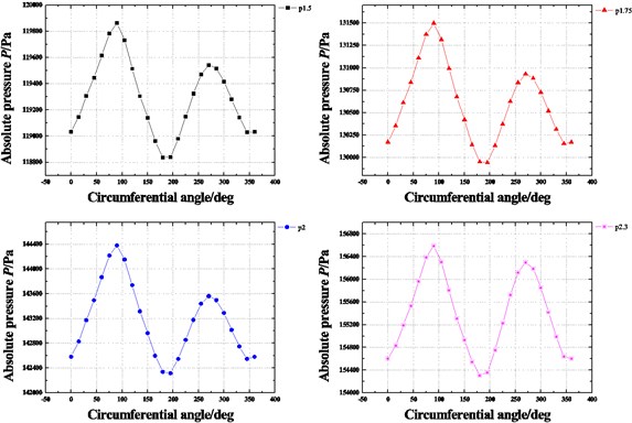
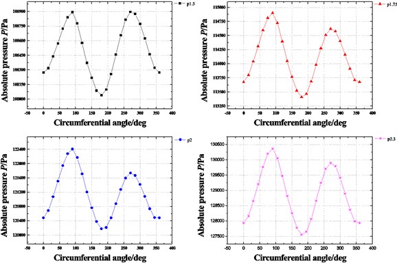
Fig. 15 shows the dynamic coefficients varying with the increasing inlet pressure when the rotor is in the tilting condition (δ=0.05 mm, θ=0.8 deg). Except for the cross-coupled damping coefficient, both the stiffness coefficient and damping coefficient increase as the inlet pressure increases. As shown in Fig. 16, the whirl frequency ratio also shows a decrease with the increasing inlet pressure. It means the higher inlet pressure tends to improve the stability when the rotor is in tilting condition. Likewise, when the rotor tilt is not taken into consideration, this conclusion is contrary to former results. Fig. 17 shows the pressure distribution in the circumferential direction of seal cavities for different inlet pressures. It can be seen that the pressure fluctuation in each cavity shows a more uniform distribution with the increasing inlet pressure. Consequently, the resultant fluid force becomes smaller and smaller. The tilting rotor shows a better stability performance for the higher inlet pressure.
Fig. 15Dynamic coefficients change with increasing inlet pressure (E= 0.1, N= 3000 rpm, θ= 0.8 deg)
a) Direct stiffness coefficients
b) Cross-coupled stiffness coefficients
c) Direct damping coefficients
d) Cross-coupled damping coefficients
Fig. 16Whirl frequency ratio changes with increasing inlet pressure (E= 0.1, N= 3000 rpm, θ= 0.8 deg)
3.5. Influence of tilt angles on dynamic characteristics of test seal
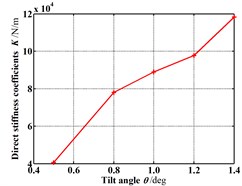
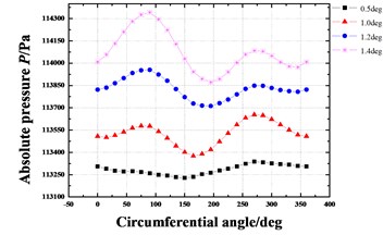
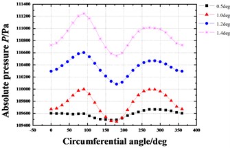
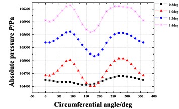
Fig. 18 shows the dynamic coefficients varying with the increasing tilt angle (δ=0.05 mm). All the stiffness coefficients and damping coefficients increase as the tilt angle increases. As shown in Fig. 19, the whirl frequency ratio also shows an increase with the increasing tilt angle. It means the rotor tilt tends to reduce the stability. Fig. 20 shows the pressure distribution in the circumferential direction of seal cavities for different tilt angles. Greater pressure fluctuation can be found for the bigger tilt angle.
Fig. 17Pressure distribution in circumferential direction of seal cavities with increasing inlet pressure (E= 0.1, N= 3000 rpm, θ= 0.8 deg)
a) Cavity 1
b) Cavity 2
c) Cavity 3
Fig. 18Dynamic coefficients change with increasing tilt angle (Pin= 1.2 atm, N= 3000 rpm, E= 0.1)
a) Direct stiffness coefficients
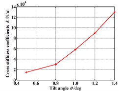
b) Cross-coupled stiffness coefficients
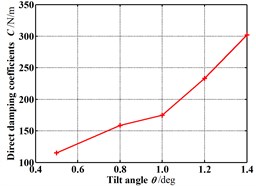
c) Direct damping coefficients
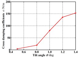
d) Cross-coupled damping coefficients
Fig. 19Whirl frequency ratio changes with increasing tilt angle (Pin= 1.2 atm, N= 3000 rpm, E= 0.1)
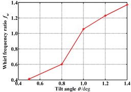
Fig. 20Pressure distribution in circumferential direction of seal cavities with increasing tilt angle (Pin= 1.2 atm, N= 3000 rpm, E= 0.1)
a) Cavity 1
b) Cavity 2
c) Cavity 3
4. Conclusions
This paper analyzed the influence of tilting rotor on the characteristics of fluid-induced vibration for labyrinth seals by the CFD method. Two labyrinth models were employed to verify and analyze the inherent characteristics of fluid-induced vibration. Different models with varying boundary conditions were performed based on our previous test seal. The following points summarize the obtained results:
1) Based on a Hirano’s compressor eye seal, the numerical results demonstrated a good agreement with that in the Hirano’s published paper. Rotational speeds have a little effect on the radial fluid-induced force. While the tangential fluid-induced force increases seriously as the rotational speed increases. Both the radial and tangential fluid-induced forces show an obvious increase when the rotor is in tilt conditions. From an efficiency viewpoint, a bigger tilt angle of the rotor is desirable. And the eccentricity existence is not beneficial to the seal performance.
2) Based on our previous test seal, the direct and cross-coupled stiffness coefficient as well as direct damping coefficient become smaller and smaller as the eccentricity ratio increases. While the absolute value of cross-coupled damping coefficient increases with the increasing eccentricity ratio. The whirl frequency ratio shows an increase with the increasing eccentricity ratio. A minor eccentricity of the rotor is desirable.
3) When the rotor tilt is not taken into consideration, several conclusions are contrary to former results. Except for the direct stiffness coefficient, both the stiffness coefficient and damping coefficient increase as the rotational speed increases in case of the tilting condition (δ=0.05 mm, θ=0.8 deg). The whirl frequency ratio shows a decrease with the increasing rotational speed. The higher rotational speed will be beneficial to improve the stability when the rotor is in tilting conditions.
4) Except for the cross-coupled damping coefficient, both the stiffness coefficient and damping coefficient increase as the inlet pressure increases. The whirl frequency ratio also shows a decrease with the increasing inlet pressure. The higher inlet pressure tends to improve the stability when the rotor is in tilting conditions.
5) All the stiffness coefficients and damping coefficients increase as the tilt angle increases. The whirl frequency ratio also shows an increase with the increasing tilt angle. It means the rotor tilt tends to reduce the stability. The efforts of this paper provide a useful insight to clearly understand the effects of tilting rotor on the static and dynamic characteristics of labyrinth seals, which are beneficial to improving the design of annular seals.
References
-
Denecke J., Schramm V., Kim S., Wittig S. Influence of rub-grooves on labyrinth seal leakage. Journal of Turbomachinery, Vol. 125, Issue 2, 2003, p. 387-393.
-
Shimada K., Kimura K., Ichikawa S., Ohta H., Aoki K. Phenomenon of labyrinth seal with low static pressure difference and large clearance – (Analysis of the internal phenomenon with CFD). Journal of Visual-Japan, Vol. 7, Issue 1, 2004, p. 63-75.
-
Picardo A., Childs D. W. Rotordynamic coefficients for a tooth-on-stator labyrinth seal at 70 bar supply pressures: Measurements versus theory and comparisons to a hole-pattern stator seal. Journal of Engineering for Gas Turbines and Power, Vol. 127, Issue 4, 2005, p. 843-855.
-
Gamal A. J. M., Vance J. M. Labyrinth seal leakage tests: tooth profile, tooth thickness, and eccentricity effects. Journal of Engineering for Gas Turbines and Power, Vol. 130, Issue 1, 2008, p. 12510.
-
EI-Gamal H. A., Awad T. H., Saber E. Leakage from labyrinth seals under stationary and rotating conditions. Tribology International, Vol. 29, Issue 4, 1996, p. 291-297.
-
Childs D. W., Scharrer J. K. Theory versus experiment for the rotordynamic coefficient of labyrinth gas seals: Part II – A comparison to experiment. Journal of Vibration and Acoustics, Stress, and Reliability in Design, Transactions of the ASME, Vol. 110, 1988, p. 281-287.
-
Scharrer J. K. Theory versus experiment for the rotordynamic coefficients of labyrinth gas seals: Part I – A two control volume model. Journal of Vibration, Acoustics, Stress, and Reliability in Design, Transactions of the ASME, Vol. 110, 1988, p. 270-280.
-
Rajakumar C., Sisto F. Experimental investigations of rotor whirl excitation forces induced by labyrinth seal flow. Journal of Vibration and Acoustics, Transactions of the ASME, Vol. 112, 1990, p. 515-522.
-
Yucel U. Effects of Labyrinth Seals on the Stability of Rotors. Lehigh University, 2000.
-
Kwanka K. Improving the stability of labyrinth gas seals. Journal of Engineering for Gas Turbines and Power, Vol. 123, Issue 2, 2001, p. 383-387.
-
Song B. H., Song S. J. Lateral forces from single gland rotor labyrinth seals in turbines. Journal of Engineering for Gas Turbines and Power, Vol. 126, Issue 3, 2004, p. 626-634.
-
Wang W. Z., Liu Y. Z., Chen H. P., Jiang P. N. Computation of rotordynamic coefficients associated with leakage steam flow through labyrinth seal. Archive of Applied Mechanics, Vol. 77, Issue 8, 2007, p. 587-597.
-
Liu Y. Z., Wang W. Z., Chen H. P., Ge Q., Yuan Y. Influence of leakage flow through labyrinth seals on rotordynamics: numerical calculations and experimental measurements. Archive of Applied Mechanics, Vol. 77, Issue 8, 2007, p. 599-612.
-
Pugachev A. O., Deckner M. Analysis of the experimental and CFD-based theoretical methods for studying rotordynamic characteristics of labyrinth gas seals. Proceedings of ASME Turbo Expo 2010: Power for Land, Sea and Air GT2010, Glasgow, UK, 2010.
-
Gao R., Kirk G. CFD study on stepped and drum balance labyrinth seal. Tribology Transactions, Vol. 56, Issue 4, 2013, p. 663-671.
-
Hirano T., Sasaki T., Sakakida H., Uchida T., Tsutsui M., Ikeda K. Evaluation of Rotordynamic Stability of a Steam Turbine Due to Labyrinth Seal Force. Zhejiang University Press, Hangzhou, 2007, p. 361-367.
-
Rhode D. L., Allen B. F. Measurement and visualization of leakage effects of rounded teeth tips and rub-grooves on stepped labyrinths. Journal of Engineering for Gas Turbines and Power, Vol. 123, Issue 3, 2001, p. 604-611.
-
Kwanka K., Ortinger W. Rotordynamic coefficients of long staggered labyrinth gas seals. International Journal of Rotating Machinery, Vol. 1, Issues 3-4, 1995, p. 285-291.
-
Schramm V., Denecke J., Kim S., Wittig S. Shape optimization of a labyrinth seal applying the simulated annealing method. The International Journal of Rotating Machinery, Vol. 10, Issue 5, 2004, p. 365-371.
-
Xi J., Rhode D. L. Rotordynamics of turbine labyrinth seals with rotor axial shifting. International Journal of Rotating Machinery, Vol. 2006, 2006, p. 93621.
-
Hirano T., Guo Z., Kirk R. G. Application of computational fluid dynamics analysis for rotating machinery – Part II: Labyrinth seal analysis. Journal of Engineering for Gas Turbines and Power, Vol. 127, Issue 4, 2005, p. 820-826.
-
Zhang W. F., Yang J. G., Cao H., Sun D. Experimental identification of fluid-induced force in labyrinth seals. Journal of Mechanical Science and Technology, Vol. 25, Issue 10, 2011, p. 2485-2494.
-
Dogu Y., Sertçakan M. C., Bahar A. S., Piskin A., Arican E., Kocagül M. Computational fluid dynamics investigation of labyrinth seal leakage performance depending on mushroom-shaped tooth wear. Journal of Engineering for Gas Turbines and Power, Vol. 138, Issue 3, 2016, p. 32503.
-
Li Z., Li J., Feng Z. Numerical comparison of rotordynamic characteristics for a fully partitioned pocket damper seal and a labyrinth seal with high positive and negative inlet preswirl. Journal of Engineering for Gas Turbines and Power, Vol. 138, Issue 4, 2016, p. 42505.
-
Untaroiu A., Untaroiu C. D., Wood H. G., Allaire P. E. Numerical modeling of fluid-induced rotordynamic forces in seals with large aspect ratios. Journal of Engineering for Gas Turbines and PowerVol. 135, Issue 1, 2013, p. 12501.
-
Pugachev A. O., Kleinhans U., Gaszner M. Prediction of rotordynamic coefficients for short labyrinth gas seals using computational fluid dynamics. Journal of Engineering for Gas Turbines and Power, Vol. 134, Issue 6, 2012, p. 62501.
-
Subramanian S., Sekhar A. S., Prasad B. V. S. S. Rotordynamic characteristics of rotating labyrinth gas turbine seal with centrifugal growth. Tribology International, Vol. 97, 2016, p. 349-359.
-
Kim E., Palazzolo A. Rotordynamic force prediction of a shrouded centrifugal pump impeller – Part I: Numerical analysis. Journal of Vibration and Acoustics, Vol. 138, Issue 3, 2016, p. 31014.
-
Moore J. J. Three-dimensional CFD rotordynamic analysis of gas labyrinth seals. Journal of Vibration and Acoustics, Vol. 125, Issue 4, 2003, p. 427-433.
-
Yan X., He K., Li J., Feng Z. A generalized prediction method for rotordynamic coefficients of annular gas seals. Journal of Engineering for Gas Turbines and Power, Vol. 137, Issue 9, 2015, p. 92506.
-
Lindsey W. T., Childs D. W. The effects of converging and diverging axial taper on the rotordynamic coefficients of liquid annular pressure seals: theory versus experiment. Journal of Vibration and Acoustics, Vol. 122, Issue 2, 2000, p. 126-131.
Cited by
About this article
Financial supports from the National Natural Science Foundation of China (11402148, 51676131, 51575105), Cultivation Program of Young College Teacher in Shanghai (ZZslg15006), Shanghai Science and Technology Commission Project (13DZ2260900) and USST Key Laboratory of Flow Control and Simulation (D15013) were sincerely acknowledged.

