Abstract
Pipe thread hardening unit had being developed, produced and trialed with usage of intensive radial ultrasonic vibrations. Microhardness trials had being held. As a result, it had been announced that microhardness was increased 2-3 times in comparison with unhardened base layer.
1. Introduction
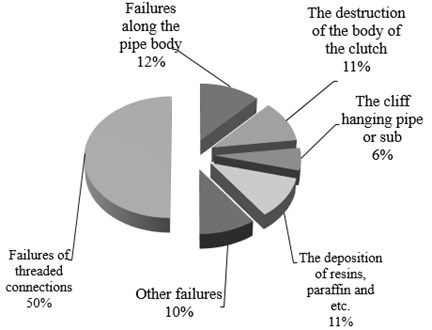
Threaded pipe connections are critical components within pipelines, for example a string of production tubing that extracts hydrocarbons from the well consists of made-up pipe sections. Subjected to heavy-duty service (high pressure, vibration, momental and tensile loads), threads often succumb to external effects as frequent failures and breakdowns occur (Fig. 1) [1].
Fig. 1Distribution of failures in oil and gas well by type
Elimination of failures and breakdowns in oil wells and specifically in gas wells is extremely costly and is estimated in tens of millions of rubles.
Due to increased technical parameters of hardware components used to create ultrasonic equipment an opportunity emerged to create powerful ultrasonic devices used for treatment of various parts and components. The capacity of modern high-powered ultrasonic devices using piezoelectric converters can amount to tens of kilowatts.
Intense ultrasonic vibrations create opportunities to acquire and observe new effects of ultrasonic treatment onto metals and alloys. Operations performed in different modes allows both to soften and harden treated base metals.
We shall consider surface plastic deformation and hardening of threads used in production tubing using an ultrasonic device that employs radial ultrasonic vibrations with output of up to 10 kW.
2. Theoretical research
Theoretical research of outer surface deformation had been held in order to develop construction of ultrasonic unit and determine conditions and force of thread deformation that can be applied to ultrasonic generator [2]. Since surface plastic deformation requires higher capacity than subsequent thread hardening, certain values of thread deformation force were taken into account while engineering the design of the ultrasonic device.
Fig. 2 presents a surface plastic deformation schematic of a thread turn [2].
Fig. 2Surface plastic deformation of a thread turn

The thread turn is represented in the form of a hollow wheel; specific deforming force is determined using an engineering method.
Specific effort for surface plastic deformation is determined through the following Eq. (1) [2]:
-2∙k∙Ϛ(R)∙h∙(1-r2)√3∙π∙J1∙(k∙R)∙(R-1)∙[R+1R∙√1+3∙μ2(1-R)2∙(1-3∙μ2y)+R-14∙R
∙(1√1+3∙μ2(1-R)2∙(1-3∙μ2y)+1R∙√R4+3)-1R∙√R4+3]
-1+2∙μy∙RR2-1∙h}∙στ
where q – specific surface plastic deformation effort using ultrasonic vibrations; ϛ –amplitude of harmonic oscillations; k – wave number; R=Rn/Rn – rvn – relative diameter of threads; J1 (kR) – first-order Bessel function, μ, μy– friction coefficients with and without ultrasound.
Deforming force P is determined from multiplication of specific surface plastic deformation effort value by its surface area value Eq. (2):
Upon determination of deforming force, the calculation of the unit’s torque is carried out, as well as strength calculations for its structural elements and ultrasonic treatment devices to treat the required thread diameter.
The principal element of the thread hardening ultrasonic unit is the ultrasonic resonant system using radial ultrasonic vibrations, the basis of which is the circular waveguide.
The circular waveguide is calculated according to the condition of its diameter being a multiple of the quarter of wave length of the sound propagated through its material.
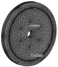
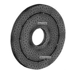
For the circular waveguide designed on the basis of Inventor we used T-FLEX PLM ‘Frequency analysis’ module that allows to calculate resonant frequencies of structural elements and corresponding wave shapes. We studied the amplitudes of ultrasonic vibrations in contact areas between the circular waveguide with the instrument and with the converters where they should be at their maximum, as well as in fixing points where preferred vibrations are those with minimal amplitude values [3].
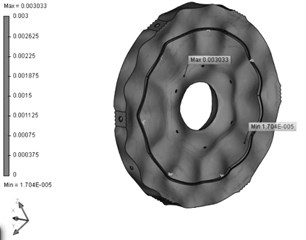
While carrying out the frequency analysis we assigned 100 types of vibrations within bandwidth of 18000-22000 Hz. As a result of computer-aided designing we determined 54 characteristic oscillations of the circular waveguide. The most ‘fitting’ one, No. 46 came at frequency of 21141,416 Hz with clearly pronounced maximum and minimum values at specified diameters of the circular waveguide. Visualization of modelling presented on Fig. 3.
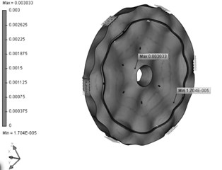
Induced oscillations were simulated similarly. Visualization of modelling presented on Fig. 4.
Fig. 3Simulation of eigenfrequency of the circular waveguide
a) 0° phase
b) 180° phase
Fig. 4Simulation of induced oscillations of the circular waveguide
a) 0° phase
b) 180° phase
3. Experimental arrangement
Based on theoretical research we designed and manufactured an experimental pipe thread ultrasonic treatment unit presented on Fig. 5.
The unit consists of the ultrasonic generator (1), six piezoelectric converters (2) mounted onto the circular waveguide (3), that also contains an accelerometer (4), connected to the oscillation sensor (8) and the ultrasonic instrument (5). The pipe (6) is fixed within clamping and rotating mechanism (7).
The unit works as follows (Fig. 6): the pipe (2) is fixed within the clamping and rotating mechanism (1). The ultrasonic generator is then switched on (Item 1 on Fig. 5), that transmits ultrasonic vibrations onto piezoelectric converters (3) and circular waveguide (4). The system reaches the resonant mode automatically through automatic frequency control. Ultrasonic vibrations are transmitted onto the ultrasonic instrument (5) to which the threaded tubing (6) is made-up. At the same time the sliding carriage (7) moves along axis of the treated pipe (2). Initially the ultrasonic treatment is employed for correction of thread profile and during the second run hardening is performed, after which the cycle is repeated.
In order to achieve the resonance between the ultrasonic resonant system (URS) and the circular waveguide active load matching was performed with the ultrasonic generator in terms of synchronism and phase coincidence based on amplitude frequency responses specified in Table 1.
Fig. 5Experimental pipe thread ultrasonic hardening unit
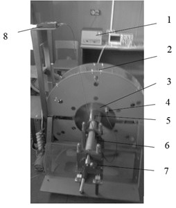
Fig. 6The scheme works of ultrasonic installation
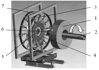
Table 1Amplitude frequency responses (AFR) of the system
No. | AFC for one converter | AFC for six converters | AFC for URS | |||
Frequency, Hz | Amplitude (ϛ), µm | Frequency, Hz | Amplitude (ϛ), µm | Frequency, Hz | Amplitude (ϛ), µm | |
1 | 19 125 | 4,2 | 20 114 | 4,0 | 18 580 | 4,2 |
2 | 19 873 | 5,1 | 20 775 | 5,2 | 19 387 | 5,1 |
3 | 19 978 | 3,8 | 20 174 | 3,5 | 20 873 | 3,8 |
4 | 20 023 | 4,9 | 19 623 | 4,9 | 20 431 | 4,9 |
5 | 21 231 | 2,7 | 21 121 | 2,7 | 21 121 | 2,7 |
In order to match operation of all of the system’s elements the parameters of each of the six converters along with those of the URS were adapted to reach optimum operational conditions, meaning that each of the six converters had to be adjusted to 19 387 Hz. After that the URS would be equipped and AFRs would be recorded again until the resonance of the entire system is achieved.
Invention patents were acquired for the manufactured and tested ultrasonic unit and instrument [4, 5].
4. Results of microhardness test
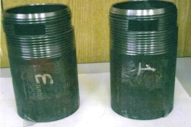
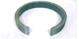
Fig. 7 presents male sections of production tubing with hardened thread from which samples were cut for microhardness testing using PMT-3 microhardness tester.
Fig. 7Preparation of samples for microhardness testing using PMT-3 microhardness tester
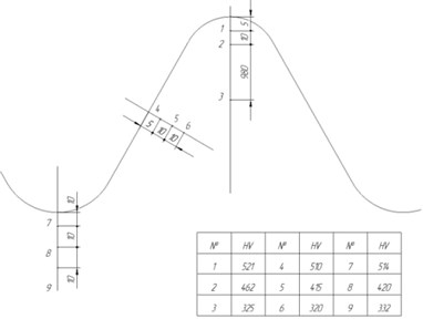
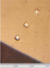
Microhardness testing chart in several areas of hardened thread is presented on Fig. 8.
As seen from Fig. 8 the microhardness values are within the range of 320-521 kg/mm2. Furthermore, microhardness decreases as the depth increases; for example, measurements in points 1; 2; 4; 5; 7; 8 at the depth of up to 15 μm showed microhardness values within 521-415 kg/mm2. As depth increases microhardness decreases as hardness gradually acquires initial values. This is very important for threads in production tubing. High microhardness values of the surface layer and relatively low hardness of the pipe body allow to avoid brittle fracture of the threaded area in operation, especially during good workover and also allow to drastically increase wear resistance of the threaded connection with the coupling.
Fig. 8Microhardness measurement in various areas of hardened thread.
5. Conclusions
In conclusion it may be noted that based on results acquired during theoretical research it was possible to design, manufacture and subject to trials the ultrasonic pipe thread hardening unit. The surface microhardness tests conducted on thread-hardened production.
References
-
Proskurin E. Protective coating: quality and durability of pipes. National Metallurgy. National Metallurgy Printing Center LLC, Moscow, Vol. 5, 2003, p. 86-96, (in Russian).
-
Evsyukov S. A., Nebogov S. M., Punin V. I., Fedotov I. L. Theoretical research of thread surface plastic deformation at action of ultrasonic vibrations. Interbranch Scientific and Technical Magazine “Vestnik Mashinostroeniya”, Moscow, Vol. 5, 2016, p. 11-17, (in Russian).
-
Kolesnikov V. V., Nebogov S. M., Punin V. I., Evsyukov S. A., Fedotov I. L. Research of disk concentrator of device for thread processing by surface plastic deformation with use of ultrasound. Interbranch Scientific and Technical Magazine “Vestnik Mashinostroeniya”, Moscow, Vol. 4, 2016, p. 53-56, (in Russian).
-
Vojder A. L., Evsjukov S. A., Morgunov V. A., Nebogov S. M., Podorjashchij D. A. Method of thread formation and strengthening in parts, for example, oil field pipes and their couplings, installation for its implementation. Federal Institute of Industrial Property, Bulletin Ru2562850C1, 2015, (in Russian).
-
Isakov S. P., Evsjukov S. A., Nebogov S. M., Podorjashchij D. A., Punin V. I. Tool of ultrasound treatment of part conical thread. Federal Institute of Industrial Property, Bulletin Ru2575515C1, 2016, (in Russian).
About this article
Research performed under the Federal Dedicated Programme “Research and Development on Priority Directions of Development of Scientific and Technical Complex for 2014-2020” with support from the Ministry of Education under Agreement No. 14.576.21.0030 dated 30.06.2014, unique Project ID: RFMEFI 57614X0030.
