Abstract
We consider the contact problems during rotor rotation at its contacting with elements of the rotor system. The two different situations are considered: a) the rotor contact with fixed stator b) the rotor contact with light movable elements (sealing rings, elastic supports, etc.). The following motion regimes are studied: rolling rotor on the stator, vibro-impact regimes, and oscillations as hula-hoop type at contact with light elements. For these cases, we obtain a solution in analytical view, which enable to find the general laws inherent in these problems. In particular, it was found: the velocity of steady rolling close to the natural frequency of the rotor system; it was proved the occurrence of two-impact mode at anisotropy of the stator elements. Also the experimental results are given.
1. Introduction
In contact regimes of rotary systems can be distinguished two different situations: 1) the rotor contact with fixed or elastically fixed rigid stator and 2) the rotor contacts with lighter movable elements (e.g., floating or finger seals, elastic supports). Contact modes in these cases essentially differ from each other. However, at all contact modes occur as a rule an emergency situation. To these problems the large number of papers is devoted, which are usually include the calculated and experimental results for specific rotor systems (aircraft engines, turbines, etc.) [1]. Besides there are comprehensive studies of analogues regimes in vibromachines [2]. This paper presents analytical solutions for such regimes and found the general laws inherent in this class of problems.
2. Permanent rotor contact with elements of the rotor system
In this case, the following regimes can occur: forward synchronous whirling and asynchronous backward whirling (rolling). At forward synchronous whirling the shaft is touched to the bearing by always one party only (the lunar motion). In the presence of oil layer can arise the self-oscillations [3].
2.1. Rolling of the rotor to stator - backward asynchronous whirling
In the absence of the oil film occurs the rolling - asynchronous backward whirling. It can occur with a sudden rotor unbalance (for example, the blade breakaway), with external impulse action (it is in fact means a rigid excitation of self-oscillations).
Kinematic rolling takes place without sliding. It is characterized by a great angular speed and considerable contact interaction force which excess the rotor weight by several orders:
where r is the shaft radius, δ is the clearance value, N is the normal pressure at the contact point.
But really the rolling is accompanied by a slippage. This gives rise to intensive wear of contacting surfaces of the rotor and the stator, which is very quickly leads to the destruction of an emergency. For example, at the Novocherkassk GRES (2002) the limit power of the normal pressure on stator was 3,4.104P where P is rotor weight. The rolling-process before the destruction lasted only 0.2 seconds.
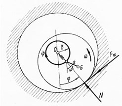
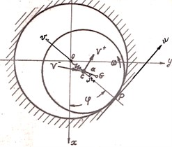
Mathematical model of the rolling mode [4] is shown in Fig. 1. In the case of fixed stator the system has one degree of freedom: it is an angle φ. On Fig. 1 are designated: O is a bearing axis, O1 is the rotor geometric center; G is the mass center; ω is an angular rotor speed; ˙φ is the angular whirling velocity; N is the normal component of the stator reaction; Ffr is the dry sliding friction force; ε=GO1 is the rotor unbalance
Fig. 1A dynamic model of the rotor rolling on the stator with slippage effect
The equation of motion of the rotor in case of rolling with a slippage:
N=m˙φ2δ+maω2cos(ωt+φ)-kδ,
where k is the equivalent shaft stiffness, f is the dry friction coefficient. Conditions of unseparated motion is N>0.
The rolling can be considered as a self-oscillating oscillations due to dry friction force Ffr=fN. Eq. (1) is an essential – nonlinear one, since the term ε/δ can be not small. Nevertheless, it can be reduced to an equation with a small parameter at nonlinear terms with help of variables change: ωt=τ, u=τ+φ+γ, γ=arctgφ, γ is a friction angle. Assuming then s=(∂u/∂τ)2, we receive:
In this equation, there is a small parameter f already, and we seek its solution by the small parameter method in the form:
Finally, after a series of transformations we find the rolling speed:
From Eq. (2) one can see that the speed of backward whirling is a periodic function. For a small unbalance it is:
So the speed of the steady rolling is located in vicinity of the system natural frequency.
Solution Eq. (2) as the sum of the fast and slow components is represented, and that is typical for problems of rotary and vibration mechanics [3].
From Eq. (2) we obtain:
The disturbance of rotor contact with the bearing occurs when the normal reaction N≤0. But it should be borne in mind that the condition N≤0 still does not mean the ending of the rolling mode, as is sometimes stated. Really it only follows that by increasing the rotor speed increases the whirling speed also. Indeed, rolling continues, but with a different whirling speed and then a normal reaction Eq. (1) remains positive. On the trajectory of eccentric point, by this the loops number is decreased as follows from Eq. (4). The rolling regime ends only after a minimum number of loops. Rolling regime replaces the vibroimpact or mixed regimes.
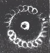
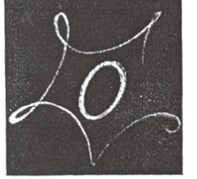
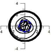
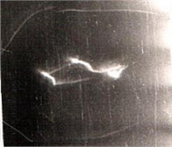
Experimental laboratory studies of shaft trajectories were carried out with help of unique optical method that offered by N. V. Zvinogrodsky [5]. At the shaft end were placed two needles: O in the center shaft and O1 – eccentric, and their trajectories are fixed. To fix each shaft revolution is arranged interrupter of light beam as a narrow plate at the edge of the shaft section. The uniqueness of the method consists in possibility to monitor not only the trajectories of the center shaft, but an eccentric point, which makes it possible to set the direction and the whirling speed. Indeed, the trajectory of eccentric point is a superposition of two motions: oscillation with the whirring frequency Ω and rotation speed around a shaft center:
In the case of forward whirling this trajectory is an epitrochoid (trajectory loops are directed inward), and in the case of backward one it is- hypotrochoid (loops are directed outward) (see Fig. 3). According to the loops number one can also easily determine the speed of the asynchronous whirling, sincen=(Ω+ω)/ω. Experimental trajectories of eccentric point at rolling regime-hypotrochoids – are shown in Fig. 3(a, b) (clearance δ=0,25 mm, the radius r= 6 mm). From Eq. (2) and Eq. (3) it follows that at the steady rolling the loops number decrease in accordance Eq. (2) by increasing the rotation speed. This fact was confirmed experimentally.
Fig. 2Experimental trajectories of eccentric point at different rotor speeds
a)
b)
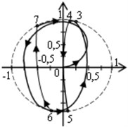
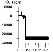
The above results coincide with the numerical results obtained independently by V. F. Shatokhin [1] for a turbine GRES (Fig. 3(a, b, c)).
Transient oscillations begin with forward whirling (Fig. 3(a)), then there are several shocks with the slip, then starts backward whirling (Fig. 3(b), (c)). Permanent running of the rotor on the stator develops after 0.053 seconds, and the rolling-speed close to the critical. This is true for non-rigid stator also: the steady rolling speed of rotor is close to the natural frequency of “rotor-stator” system.
Fig. 3The process of setting the rolling speed close to the natural frequency: a) transient oscillations, b), c) the steady rolling at a speed close to the critical
a)
b)
c)
2.2. Permanent contact of the rotor with movable light system elements
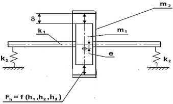
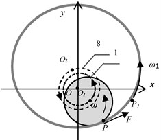
For high-speed rotors are frequently used the floating seals. In the clearance between the rotor and the ring act the hydrodynamic forces, thus causing interconnected vibrations of rotor and rings. Due to the rotor unbalance it can be in contact with the ring, and there is a rolling of the ring on the rotor (such as hula-hoop). The motion equations are [3, 6]:
=m˙φ2δ+maω2cos(ωt+φ)-p1δ.
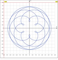
Fig. 4a), b) Dynamic model of the rotor motion in contact with a light seal ring, c) ring trajectories
a)
b)
c)
In Eq. (5): p1=p1nω2/ω2n, p2=p2nω/ωn are the coefficients of hydrostatic and hydro-damping forces.
Unseparated condition, as above: N> 0. We believe that the ring has a little effect on the rotor motion, and it makes circular oscillations due to its unbalance. However, unlike the rolling case in Section 2.1, here the rotation direction of the ring coincides with the rotation direction of the rotor, so arise a direct whirling. Therefore, the trajectory of each ring point is epitrochoid (loops are directed inward). In the absence of slippage Eq. (5) has a solution:
that means a synchronous whirling of ring with the rotor, but with a phase shift equal to φ0= const. The rings trajectories on Fig. 4(c) are represented (for R=1.2r).
In contrast [4] in this case the difference R-r is small.
3. Vibro-impact regimes
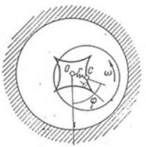
Dynamic model describing the vibro-impact regimes of rotor at its impacts with a fixed stator is shown in Fig. 5.
Fig. 5Vibro-impact regimes at the rotor impacts with a fixed stator: a) the rotor in the fixed stator, b) symmetrical impacts of balanced rotor with the stator
a)
b)
We use the theorem of momentum, impulses theorem, impacts conditions (Newton's hypothesis), slippage during the impact time:
Su=-fSv˙v+G-ω+asinω+t0=-e(˙v-G-ω-asinω+t0).
We have a system of 5 equations Eq. (6) for 5 unknowns u+G, v+G, ω+, Su, Sv. These equations are solved by stitching method [7], in which the intervals free rotor movement without contact with the bearing and the impact moment are joined. Consider two extreme cases: the rotor into the fixed hard stator and rotor on anisotropic supports.
3.1. Balanced rotor in fixed stator
When absolutely rigid stator and balanced rotor then the whole system and, consequently, the trajectories of rotor center are symmetrical relative bearing axis (Fig. 6(b)). The motion trajectories of the rotor in this case can be found analytically. The equations of the shaft between of impacts [4]:
By integrating, we find the trajectory of the rotor for the conservative impact (e= 1) (Fig. 6(b)):
where H, D, C0 are determined by the initial conditions.
3.2. Vibro-impact modes of the rotor on anisotropic supports
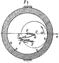
Let’s consider the vibro-impact regimes of unbalanced rotor on anisotropic support [3]. We show that in this case there is a two-impact mode in the plane of the lowest or the highest hardness, depending on the mass ratio of the rotor and support (Fig. 6).
In the case of an anisotropic support the impact conditions along the axes x and y will be different, because after the impact there is also a support displacement. From Eq. (6):
where m1 is stator mass, m2 is rotor mass.
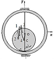
Fig. 6Unbalanced rotor on anisotropic support: a) two- impact mode of the rotor with heavy support, b) experimental trajectory of the rotor center at the two- impact mode, c) two- impact mode of the rotor with a light support
a)
b)
c)
Rotor impacts with heavy support (Fig. 6(a)). When the mass ratio of the rotor and stator μ=10≫1, e=0.55 we obtain from Eq. (7): ˙x+1≈˙x-1≈const, ˙y+1<˙y-1, i.e. ˙x+1>˙y+1. After impact, the equation of the rotor motion:
Because now ˙x+1>˙y+1, the trajectory of the rotor center after each impact will have a tangent parallel to the axis x (Fig. 7). And after the n+ 1st period:
and so on.
Since y1(T1+T2+...Tn)→0 then the two- impact regime is established in a free direction.
In practice, it is set very quickly: after 3-4 impacts. Experimental trajectories of the rotor centre are shown in Fig. 6(b).
The rotor impacts with a light support. Let the masses of rotor and support are equal to each other (Fig. 6(c)). Then μ=1, if the impact is conservative, that is, the coefficient of restitution e= 1, hence˙x+=0,˙y-=˙y+. Thus, after the first and subsequent impacts will have from Eq. (6):
And the two- impacts mode is set in the direction of support fixing.
3.3. Vibroimpact rotor modes with sealing ring
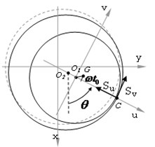
These modes differ in that ring, to which impacts is much easier then rotor (impacter body) and a rebound after the impact occurs just at the ring [8] (Fig. 7). Fig. 7 is indicated: G – rotor center of mass, O2 is the ring geometric center, a=O1G is rotor eccentricity, C – impact point.
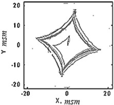
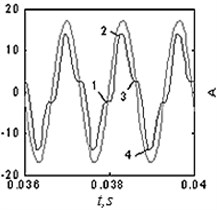
The equations of motion in this case received as above from: theorem of momentum and impulses theorem, impact conditions, slippage at impact time. Finally, we have 7 equations for seven unknowns: ˙u+1, ˙u+2, ˙v+-1,˙v+2ω+,Su, Sv. This gives rise both synchronous and asynchronous vibro-impact regimes [8, 9]. At synchronous mode (Fig. 7(a)) the oscillation periods of rotor and the rings are the same and 4 impacts occur over the period of rotor rotation. Comparison of Fig. 7(b) and Fig. 5(b) shows that the rotor trajectories at impact with a heavy support and the trajectories of light rings in its impacts with rotor are the same. Thus, these problems are mutually reversible.
Fig. 7Vibroimpact modes of the rotor with light seal: a) calculation model, b) the ring trajectory at synchronous vibro-impact regimes with 4 impacts for period; c) oscillations of the rotor (1) and the ring (2) in synchronous mode
a)
b)
c)
4. Conclusions
1) The rotor angular speed at steady rolling is close to the natural frequency of the rotor.
2) At the vibro-impact regimes with anisotropic support occurs the rotor two-impact regime in the plane of the lowest or the highest hardness, depending on the mass ratio of the rotor and support.
3) The character of the rotor trajectories at contact with a fixed stator and also the trajectories of the light movable elements during their contact with the rotor are mutually reversible.
4) At permanent contact of rotor with light rings occurs the forward rolling as hula-hoop.
References
-
Shatochin V. F. Vibrations of Turbogenerator Rotors with Rolling of Rotor to Stator. Modeling Techniques and Software Tools. Lambert Academic Publishing, 2016, p. 308, (in Russian).
-
Blechman I. I. Vibration Mechanics. Nauka, Мoscow, 1994, p. 398, (in Russian).
-
Poznyak E. L. Nonlinear Oscillations of the Rotor on Sliding Bearings. Nauka, Moscow, 1972, p. 261, (in Russian).
-
Banakh L. Ya Some effects arising during the shaft motion in the bearing with a clearance. Mashinovedenie, Vol. 1, 1965, p. 70-79, (in Russian).
-
Banakh L. Ya, Dimentberg F. M., Zvinogrodskiy N. V. On the Occurrence of Parametric Resonance of a Horizontal Shaft with a Load Having a Bearing with Radial Clearance. Izvestiya AN, Department of Technical Science, Mechanika i Mashinostrojenie, 1961, p. 159-162, (in Russian).
-
Belyakov A. O., Seyranian A. P. The hula-hoop problem. Doklady Physics, Vol. 55, Issue 2, 2010, p. 99-104, (in Russian).
-
Kobrinskiy A. E., Kobrinskiy A. A. Two-Dimensional Vibro-Impact Systems (Dynamics and Stability). Nauka, Moscow, 1981, p. 335, (in Russian).
-
Banakh L. Ya, Morozova G. N., Nikiforov A. N. Features of vibro-impact regimes in rotary systems. Proceedings of the 8th Russia Scientific Conference “Nonlinear Oscillations of Mechanical Systems”, Vol. 2, 2008, p. 34-38, (in Russian).
-
Nikiforov A. N. Generalized mathematical model of Jeffkott-Laval rotor with considering slippage and misalignment when contacting with stator. Vestnik Nauchno – Technicheskogo Razvitiya Vol. 5, Issue 57, 2012, p. 41-56, (in Russian).
