Abstract
This work analyzes the influence of electromagnetic stiffness on coupled micro disturbance behavior of 32 and 64 subdivisions (SD) Solar Array Drive Assembly (SADA). The problem geometry consists of SADA supporting and operating rigid load through transmission shaft. Mathematical model of stepper motor, used as SADA, with two phases and four beats is developed to determine output excitation torque and electromagnetic stiffness. Keeping in view the reduction ratio, number of rotor teeth, beats and subdivisions; active and dead load SADA vibration model is developed. Rigid load operated by SADA is approximated into motor torsional spring moment of inertia dynamic system to obtain frequency response of mechanical configuration. The developed mathematical model contains information about moment of inertia of load, stiffness of electromagnetic spring, stiffness of transmission shaft and moment of inertia of SADA rotor. Results obtained from analytical calculations are validated by experimentation and simulations run in Matlab/Simulink. Analysis reveals that increase of electromagnetic stiffness, subdivisions number and rotor teeth leads to increase in stability of SADA operated system. The research lays a firm basis for study on vibration attenuation and analysis of SADA disturbances during in orbit operations.
1. Introduction and background study
Scientific missions are highly reliant on accurate pointing and resolution performance of their pay loads. Their precision is mostly degraded by micro vibrations generated by static and dynamic unbalanced forces generated by rotary mechanical systems [1], including Reaction and Momentum Wheels (RWs & MWs), cryo-coolers, Control Moment Gyroscopes (CMGs), mobile mirrors and Solar Array Drive Assemblies (SADA) [2], mounted to spacecraft body. These disturbances are characterized by broad band and low frequency range that are able to excite structural modes of the system leading to an increase in noise experienced by satellite [3].
The vibrations phenomenon of RW and MW are well documented [4, 5] but complex disturbances induced by SADA have gotten little consideration. SADA is a typical revolving component in spacecraft that provides linear or angular displacement, to acquire solar energy, when an electrical input is given to the system [6]. No doubt, its operation is accurate and stable but every input of pulse causes it to produce impact load. Therefore, SADA possesses large excitation energy and dense distribution of excited and complex coupled natural frequencies that have a very slow attenuation process because of absence of air damping in space. This disturbance nature of SADA motivated Xia [7] to research the mechanism of electromagnetic vibrations and propose drive circuit to damp its amplitude. Zhang [8] added by suggesting a controller for torque compensation to enhance stability of SADA speed during operation. Bodson [9] provided an expression for electromagnetic frequency; while, in [6] its existence is verified through simulation and experimental testing. In [10, 11] dynamic models of SADA are proposed keeping in account its friction and fluctuation torque. Efforts are extended to research on the coupling effect between SADA and its operated load. Chen [12] changed the stiffness of transmission shaft in coupled mechanical system to study disturbance responses. At present the research is more inclined towards SADA subdivisions drive (SDD) scheme [13] to improve resolution, stability and accuracy of operation, but disturbances induced by it still exist. However, the spectral line of disturbance is reduced after micro stepping of full current wave.
This work considers SADA rotor specifications as study object and compares the influence of electromagnetic spring stiffness on coupled micro disturbance behavior of SADA operated system. Stepper motor driving rigid load through transmission shaft has 2 phases, 4 beats and is operated with 32 and 64 subdivisions. The coupled micro disturbance responses are investigated using analytical, simulation and experimental techniques. In the proceeding sections mathematical model for SADA disturbance is conversed, approximate analytical coupled dynamic model of SADA operating rigid load is provided next, then its disturbance response (with and without load) in different subdivisions drives is tested, dynamic system is simulated next, followed by discussion on results, conclusions and future recommendations.
2. Disturbance modeling of SADA
SADA micro vibrations come from three main sources; (1) Electromagnetic coupling disturbances (2) Electronic impact vibrations induced during input of pulse signals (3) Coupled vibrations excited by interference of active and natural frequencies of system.
2.1. Mathematical model for electromagnetic vibrations
The excitation output torque, Tex_out, of stepper motor after receiving input power is achieved by derivation of magnetic energy Me to angle θ turned by SADA rotor [6] i.e.:
Here, Etc and D are the electromagnetic and detent torque coefficients respectively. The second part in Eq. (1) i.e. detent torque is far less than electromagnetic torque (first part in Eq. (1)) and can be ignored. So, Tex_out reduces to:
where, i= 1, 2, 3, …, λ and λ=2π/(bn×nsd). Using small angle assumption i.e. sinϴ~ϴ in Eq. (2) gives following solving formula for electromagnetic stiffness Kems:
Kems, in Eq. (3) is the source of electromagnetic coupling disturbance. It depends upon electromagnetic torque coefficient, the current amplitude and number of teeth in SADA rotor. When SADA runs without load, electromagnetic disturbance is very large and is difficult to measure. So, it is suggested to operate SADA with some rigid load to measure its accurate electromagnetic disturbance dynamics.
2.2. Active vibration model for input digital pulse signals
When an electrical pulse signal is contributed, SADA rotor causes the solar array to move in a specified direction. However, every electronic pulse signal induces impact load leading to active vibration disturbance of SADA. Use of reduction ratio (100) existing between rotor (7.27×10⁻³ rad/s) and solar array speed (7.27×10⁻⁵ rad/s) lead to formulations for period T and active frequency f0 of SADA impact induced disturbance.
Ω0 is array speed, ∆ the reduction ratio, is number of subdivisions, and are the beat and teeth numbers respectively. The discrete active vibration frequency i.e. leads to disturbance model of SADA running without load in different SD number.
where, in Eq. (5) is the disturbance force for any SDD, is the frequency of number harmonic, is the amplitude coefficient of and is the phase of .
3. Vibration model of SADA driving rigid load
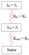
The configuration of this mechanical system consists of rigid load that is precisely rotated by stepper motor through transmission shaft. The mechanical system is approximated to motor-torsional spring-moment of inertia dynamic system (Fig. 1(c)). Approximated system consists of stiffness of transmission shaft , electromagnetic spring stiffness , moment of inertia of rigid load and rotor’s moment of inertia . The undamped free vibration equations of motion for simplified two DoF dynamic model are presented in Eq. (6).
To solve these dynamic equations solution of the form, and , is assumed. Eq. (7) is obtained by setting the determinant of coefficients of and equals to zero.
Eq. (7) is the characteristic equation to get frequency response of the system. Dynamics of approximated model (Table 1) is determined using parameters given in Table 2.
Table 1Natural frequencies of mechanical system
Rotor teeth | 50 | 100 | 150 | 200 | 250 | 300 |
(Hz) | 4.96 | 6.91 | 8.35 | 9.52 | 10.50 | 11.36 |
(Hz) | 90.00 | 91.27 | 92.52 | 93.77 | 95.01 | 96.24 |
is the electromagnetic frequency and is associated with natural frequency of load operated by SADA. In general, when SADA is coupled to rigid load its disturbance frequencies consist of active vibration frequencies, their harmonics and natural frequencies of mechanical system.
4. Force/moment testing platform
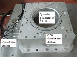
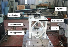
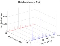
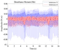
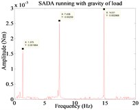
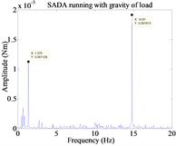
SADA behavior with 32 and 64 SDD is experimented on micro vibrations test platform, equipped with piezoelectric sensors, to determine the general vibration response when it is operated without load and with some random rigid load. In order to simulate the working environment in space a gravity unload device consisting of rigid holder, linear and air (rotating system) bearing is introduced in test platform. A rigid load with large moment of inertia is mounted on top of SADA (Fig.1b) and disturbance amplitude considering gravity of load is compared for 32 and 64 SDD. Fig. 2(a-b) reveal that for 32 and 64 SDD the number of excitation inputs to the system per second are 7.4 and 14.8 respectively. So, SADA with 32 SD excites structural natural frequencies more frequently because of higher number of active harmonics. Moreover, 32 SDD possess higher resonating zone and develop more chances to interfere with structural natural frequencies. Therefore, results from experimentation with gravity of load Fig. 2(c-d) deduce that SADA with SD 32 exhibits higher disturbance amplitude because of comparatively unstable nature of this drive.
Fig. 1SADA disturbance investigation. a) No load micro vibration test setup b) SADA running with rigid load c) Simplified dynamic model of mechanical system
a)
b)
c)
Fig. 2Micro vibrations of SADA. a) No load SADA disturbance in frequency domain b) No load SADA disturbance in time domain c) and d) SADA operating rigid load under 32 and 64 SDD respectively
a)
b)
c)
d)
Fig. 3Matlab/Simulink model for SADA supporting rigid load

Table 2Simulation Parameters
Parameter | Value | units |
50, 100, 150, 200, 250 and 300 | - | |
4 | - | |
32 and 64 | - | |
50, 100, 150, 200, 250 and 300 | Nm/rad | |
10 | Nm/A | |
0.005 | kg·m2 | |
0.045 | kg·m2 | |
0.1 | A | |
118.2 | Nm/rad |
5. Matlab/simulations and analysis
Matlab/Simulink toolbox is used to simulate disturbance model of SADA driving rigid load. The dynamic equations of this mechanical system are:
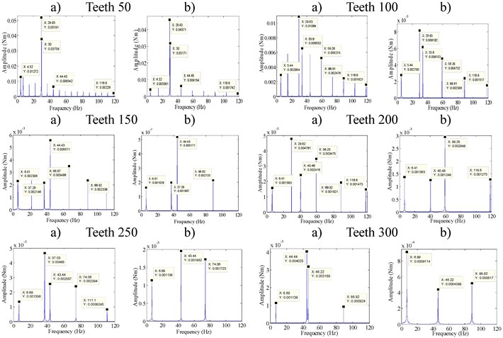
The principle simulation diagram and simulation parameters used are given in Fig. 3 and Table 2 respectively. The corresponding analysis results are provided in Fig. 4.
6. Discussion
Electromagnetic stiffness depends upon electromagnetic torque coefficient, the current amplitude and number of rotor teeth. Simulations are run for its constantly increasing values that in turn depend upon number of teeth in SADA rotor. Discussion below, based on Fig. 2 and 4, deduce the effect of increase in electromagnetic stiffness on disturbance response of SADA.
Fig. 4Simulation results for different values of electromagnetic stiffness. a) 32 SDD b) 64 SDD
1) As SADA supporting rigid load is approximated with 2-DoF mechanical system so, its disturbance response consists of two natural frequencies, active vibration disturbance frequencies and their corresponding harmonics. Out of two natural frequencies the first one is electromagnetic and the subsequent is natural frequency of operated mechanical load.
2) Amplitude of fundamental active disturbance is maximum for any SDD that proceeds in descending manner towards higher frequency domain. However, if any harmonics of active vibration fall near or on system natural frequency then the disturbance response amplitude shows significant and abrupt magnification in amplitude of vibration.
3) An increase in rotor teeth number improves that in turn reduces the disturbance amplitude and improves system stability. The highest disturbance response i.e. 0.05191 Nm is observed when rotor teeth is kept 50 while it is least when rotor teeth number is improved to 300. Moreover, an increase in number of rotor teeth reduces the frequency of occurrence of active disturbances. It reduces the chances of interference between electronic and natural frequencies hence avoiding the occurrence of resonance and corresponding system instabilities.
4) For any number of rotor teeth, disturbance amplitude for SD 64 SADA is lower as compared to 32 SDD. The comparatively smaller resonating zone of 64 SDD ensures it stable response.
5) Natural frequencies of flexible solar array mostly lie in lower frequency domain. So, if rotor teeth number is reduced it results in corresponding decrease in electromagnetic stiffness causing the active and electromagnetic frequencies to fall in lower frequency domain and increase their chances to interfere with natural frequencies of flexible array. So, increase in rotor teeth and SDs helps to move active and electromagnetic frequencies towards higher frequency domain, reduce the chances of resonance and contribute to improve system stability.
Out of the analyzed SADA configurations, 64 SDD with 300 rotor teeth exhibits smooth and noiseless operation, less number of excited frequencies and very reduced amplitude of excited frequencies, so, it is more preferred where impeccable operation is required.
7. Conclusions and future recommendations
An approximate analytical model, simulation analysis and experimentation are completed to study the effect of variation in rotor specifications on disturbance response of 32 and 64 SD SADA. The problem geometry consisted of SADA supporting and operating rigid load through transmission shaft. The physical change is introduced in system by changing the number of rotor teeth and corresponding electromagnetic stiffness. Analytical frequency response is approximated by transforming the mechanical system to motor torsional spring moment of inertia system. The results obtained from mathematical model are compared with simulations run in Matlab/Simulink and experimentation to check the validity of developed model and SADA response. All of the analysis results showed consistency leading to the conclusion that increase in number of subdivisions and rotor teeth improves frequency response and stability of the system. The main contributing factor to instability is interference of active and natural frequencies of the system so, this research targeted to minimize such conditions. However, at present the authors are making effort to research active decoupling vibration phenomenon. The current and future contribution will provide a significant help in vibration damping study and control of SADA induced disturbance in satellite.
References
-
Omiciuolo M., et al. Micro-vibration performance prediction of SEPTA24 using SMESIM (RUAG Space Mechanism Simulator Tool). 15th European Space Mechanisms and Tribology Symposium, The Netherlands, 2013.
-
Xing G., Youping W. The universalization, serialization and modularization design of solar array drive assembly (SADA). Chinese Journal of Space Sciences, Vol. 22, 2002, p. 55-67.
-
Wagner M., et al. European Space Agency (ESA): New Reaction Wheel Characterization Test Facility (RCF). Advances in the Astronautical Sciences, Vol. 144, 2012, p. 537-556.
-
Liu K. C., M. P., Blaurock C. Reaction wheel disturbance modeling, jitter analysis and validation tests for solar dynamics observatory. AIAA Guidance, Navigation and Control Conference and Exhibit, Guidance, Navigation, and Control and Co-located Conferences, 2008.
-
Weiyong Z., et al. Analysis and testing of microvibrations produced by momentum wheel assemblies. Chinese Journal of Aeronautics, Vol. 25, Issue 4, 2012, p. 640-649.
-
Yang Y. L., et al. Experiment and simulation of electromagnetic stiffness for stepper motor. Applied Mechanics and Materials, 2010.
-
Li X. The primary research on low-frequence resonate of step-motor and it’s damping methods. Journal of Shenyang Polytechnic University, 1994.
-
Zhang M., et al. A high stability control method for solar array drive mechanism. Aerospace Control and Application, 2010.
-
Bodson M., Sato J. S., Silver S. R. Spontaneous speed reversals in stepper motors. IEEE Transactions on Control Systems Technology, Vol. 14, Issue 2, 2006, p. 369-373.
-
Si Z., Liu Y., Li K. Research on modeling and driver design of solar array drive assembly. Aerospace Control Applications, Vol. 36, 2010, p. 13-19.
-
Szolc T., et al. Dynamic investigations of electromechanical coupling effects in mechanisms driven by the stepping motor. Journal of Theoretical and Applied Mechanics, Vol. 50, Issue 2, 2012, p. 653-673.
-
Chen J. P., Cheng W., Han W. Analysis and simulation of stepper motor disturbance considering structural coupling. Applied Mechanics and Materials, 2014.
-
Xi J., Liao G., Yang W. Study of stepping motor subdivision driver. International Conference on Intelligent Computation Technology and Automation, 2010.
