Abstract
Fine-layered mountain mass with plane-parallel inclined layers is presented by anisotropic (transtropic) body with inclined plane of isotropy. A long horizontal cavity of arbitrary orientation and section shape is that medium; it is strengthened by an elastic anisotropic finishing. The interaction between the finishing and viscos-elastic rock medium is studied. The seismic-stress state of the “inishing-rock” system under aggregate action of long tension-compression and shear waves in conditions of generalized plane strains is investigated by using the quasistatic approach and complex potentials method. The procedure of research of seismic oscillations of a complex structure rock with multipurpose underground cavity using finite elements method and strong earthquake oscillograms is presented here.
1. Introduction
A mountain rock has property of elastic anisotropy, which first all is the consequence of lamination and cracks in the bulk of the rock. The expedience of taking this property into account is indicated at [1, 2], who considered only horizontal lamination. Then the problems of elastic distribution of stress along single and double cavities in plane deformation were solved in papers [3, 4]. Visco-elastic anisotropic (transtropic) models of fine-layered rock with inclined plane of isotropy [5, 6] enabled not only to take account of inclined lamination of the rock, but to divide long horizontal cavities into drifts, crosscuts and diagonal workings, differently oriented relatively to the layers extension line. This also enabled to observe the initial static stability of cavities, influence of rock creep property on the state of transtropic rock near workings, and the effect of long tension-compression and shear waves to seismic resistance of non-strengthened underground structures of arbitrary profile. The paper contains some results of research of elastic trans tropic finishing of horizontal underground cavity of arbitrary orientation and section form, and viscos-elastic mass both in conditions when the creep of anisotropic mountain rock shows its isotropic properties, and under action of long seismic tension-compression and shear waves in conditions of generalized plane deformation. Problems of seismic oscillations of underground cavities in structure medium were considered, with the use of actual earthquake accelerograms and finite elements method.
2. Materials and methods
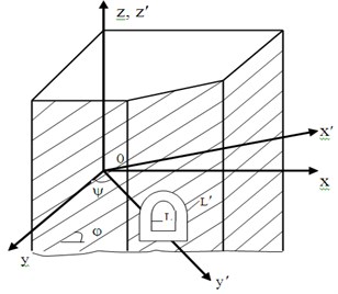
A transtropic mountain rock mass with extended horizontal under-ground cavity of deep location and arbitrary orientation relatively to isotropy plane extension line is considered. The longitudinal axis of the cavity coincides with OY axis (see Fig. 1). The cavity is strengthened by elastic finishing from anisotropic material. It is considered that the beginning of “elastic finishing-creatable mass” system interaction coincides with the beginning of display of rheological properties of the rock:
where: ak1n (N=1, 2, 3, 4; n=1, 2,...,N) given real constants, that define the of internal (k=2), external and the rock (k=1) contours; θ – the angle, counted from the horizontal OX axis. The equations of the generalized Law of Gook for transtropic mass with cavity in condition of generalized plane deformation are written in the following way [5-6]:
where:
where En, νn, Gn(n=1, 2, 3, 4...) elastic characteristics of trans tropic mass; φ – the inclination angle of the isotropy plane; ψ – the angle of deflection of the cavity long-itudinal axis from the extension line of the isotropy plane. The equations of the finishing material state have the form Eq. (2) in Eq. (3) but there the elastic constants En, νn, G2 (n=1, 2, 3, 4...) and angles φ, ψ should be replaced correspondingly by parameters E0n, ν0n, G02, φ0, ψ0.
Fig. 1Parametric equations of the finishing and rock contours are given as follows

Solution of the contact problem of interaction of the elastic finishing with the creatable transtropic mass is carried out by variable modules method with the use of Volterr principle [7] through replacement of rock elastic constants En, νn, G2, that are included into expressions for components of additional stresses and displacements, by corresponding time integral operators:
Mk(t-τ), Ln(t-τ) independent heredity cores.
In general case the determination of creep cores parameters of transtropic rock is difficult. Therefore, it is necessary to their number using the assumption about isotropic properties of anisotropic mass creep. Then starting from Abel’s creep core and using the algebras of Rabotnov’s Э*α – operators we’ll obtain:
where, α, δ creep parameters, 0<α<1.
The problem is solved in two stages. At first the mapping functions of the exteriors of the Lkj(z2j=x+η2jz) finishing contours and the Lj(zj=x+μ1jz) rock contour on the exterior of unit circle are composed as follows:
Mlkj,s are found through constants ak1n from Eq. (1). Then the solution is obtained. The complex potentials φ2j(z2j,t) for area of the finishing are presented as a sum of two series with unknown coefficients; series on P1n(z2j,t), (j=1, 2, 3, 4...). Faber polynomials inside L1j contours and series, holomorphic outside L2j contours:
The φ1j(z1j,t) potentials, characterizing temporary stressed state of the mass, are given in the following form:
the Bj and Cj(C1=0) constants are connected with main stresses [5].
Expanding the potentials Eq. (10) in Eq. (11) into series in positive and negative powers of σ=exp(iθ) on L1j, L2j, Lj contours, the infinite system of linear algebraic equations in variables ajn(t), bjn(t) and cjn(t) obtained from boundary and contact conditions, which is solved by reduction method.
3. Results and discussion
The complexity in research of a seismic-stressed state of underground cavities finishing’s under action of earthquake is caused by the difficulty in detecting the mechanism of their interaction with quasi-longitudinal and quasi-lateral waves in the anisotropic bulk of a rock. These waves are tension-compression and shear waves. The rigorous mathematical analysis of such interaction is difficult even for an isotropic mass. Therefore, in research of the seismic-stressed state of a cavity in the trans tropic bulk of rock and in calculation of its deformable finishing is expedient to apply the approximate quasi static approach, which is valid when the length of a seismic shear wave with dominant period T is greater than the largest lateral diameter of the cavity [6] not then thrice.
The problem of generalized plane strain concerning the seismic-stressed state of underground cavity, strengthened by a trans tropic finishing, in quasi-static formulation is stated in a following way: to find maximal seismic stresses in “elastic finishing-mass” system, when its contours are described by equations Eq. (1), and when the greatest seismic stresses in a continuous trans tropic body, caused by distribution of quasi-longitudinal and quasi-lateral waves with velocities Vp, Vsv and Vsh correspondingly, work on “infinity”.
The components of the basic maximal seismic stresses, caused by distribution of waves, in cross direction to the isotropy plane extension under arbitrary angle α (variant 1) are expressed by formulas:
{σ∞y,max=±T2πγKcξmaxVp,σocx,max=λxσocy,max,σocz,max=λzσocy,max,τocyz,max=±T2πγKcVsv,τocxy,max=±T2πγKcVsh,τocxz=λxzσocy,max,
here λy, λz coefficients of lateral seismic pressure; γ the solid weight of rock; Kc the seismicity coefficient, depending on earthquake magnitude; ξmax=1.1. In case of horizontal distribution of waves along the isotropy plane basic extension line (variant 2) the stresses in the solid mass are defined by expressions.
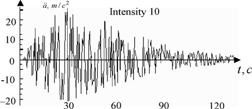
Fig. 2Synthetic accelerogram of a 10 intensity earthquake

The Seismic stresses in the finishing and in the mass are found with the help of potentials Фlj(zlj) (j=1, 2, 3; l=1, 2), having form as at Eq. (5) in Eq. (6) and Eq. (7) excluding time t. The constants Bj and Cj are expressed through the basic seismic stresses Eq. (11). Further way of solution of quasi-statics is to the problem of the previous chapter.
4. Conclusions
Consideration of seismic oscillations of underground cavities comes upon difficulties due to spatial character of calculation schemes, lack of information about kinematic parameters of destructive earthquakes, complexity of dynamic interaction with surrounding soil mass, and in homogeneity of engineering and geologic conditions of building site. The mechanism of dynamic work of underground cavities can be studied on the basis of account of instrumentally recorded kinematic characteristics of an actual earthquake, indicating a complex structure of the bulk of rock. Analytical methods appear to be powerless here. In this aspect the finite elements method is the only working tool for research of free and forced oscillations of underground structures in the laminated trans tropic bulk of rock, that are situated either in conditions of generalized plane strain, or spatial position. The eight-joint isoperimetric elements have been used. Dimensions of calculated domain have been defined from assumption that existence of a cavity does not effect on a period of a normal mode of vibration of mass. The effect of the angles φ and ψ, the depth of the cavity H location, the section form, and its driving technique on modes of vibration has been clarified. Forced oscillations of extended and three-dimensional underground cavities in a laminated mass under strong 9-10 magnitude earthquakes have been studied by finite elements method. The most intensive parts of the Gazli earthquake accelerogram (17.05.1976) have been used by tabulating with the Δt=0.23 sec. At first the resolving system of differential equations of dynamic balance of finite elements with masses in joints have been derived taking the damping matrix after Remyu. The main system is solved by two methods: the method of displacements decomposition in modes of normal vibration, and of the direct integration by time steps. The advantages and disadvantages of these method for computer calculation have been pointed. In general, the results of calculation by both methods appeared to be close however the second method gives underrated values.
References
-
Lehnitsky S. G. Theoretical research of stresses in elastic anisotropic mass near underground working of elliptic section. Proceedings of VNIMI, Vol. 44, 1962, p. 124-130.
-
Savin G. N. Some Problems of Elasticity Theory of Anisotropic Medium DAN USSR. Vol. 5, 1939, p. 27-35.
-
Cosmodamiansky A. S. Determination of Stressed of State of a Mass Near Horizontal Mountain Workings. Research of Mountain Pressure, M. Gosgortechizdat, Vol. 4, 1962, p. 75-85.
-
Cosmodamiansky A. S. Approximate Method for Determination of Stressed State of Anisotropic Mass with two Identical Elliptic Workings. Vol. 3, 1962, p. 97-115.
-
Erzhanov Zh. S., Aitaliyev Sh. M., Masanov Zh. K. Stability of Horizontal Workings in Inclined Laminated Mass. Alma-Ata, Nauka, Vol. 15, 1971, p. 71-85.
-
Erzhanov Zh. S., Aitaliyev Sh. M., Masanov Zh. K. Seismic-Stressed State of Underground Structures in Anisotropic Laminated Mass. Alma-Ata, Nauka, Vol. 52, 1980, p. 27-36.
-
Tursinbay Turymbetov The stress-strain state of the two shtreks of cros-sectional shape and the depth of a weighty obliquely layered mas if system with slits in terms of elastic deformation of rocks. International Journal of Latest Research in Science and Technology, Vol. 3, Issue 6, 2014, p. 29-32.
