Abstract
In this paper, the static bifurcation and dynamic bifurcation of rolling mill system with torsional-horizontal coupling vibration are studied. Firstly, the dynamic equation of torsional-horizontal coupled vibration of rolling mill main drive system is established. Rolling mill is driven by the gear pair, so the torsional vibration of the gear pair, the horizontal vibration and the friction factor are considered in the dynamic equation. Then the equivalent low-dimensional bifurcation equation, which can reveal the system nonlinear characteristics, is obtained using Lyapunov-Schmidt method, and the system static bifurcation characteristics are studied using singularity theory. Lastly, the bifurcation condition and stability of the system with dynamic Hopf bifurcation are studied using Hopf bifurcation theorem. Numerical simulation of the actual parameter values confirms the analytical results.
1. Introduction
With the development of modern steel rolling industry, rolling mill is required to have high precision and high dynamic performance. However, unstable vibration has been recognized as a major restriction in rolling productivity [1], so many scholars have been devoted to the study of rolling mill vibration. A large number of researchers have studied rolling mill system from the perspective of the torsional vibration. Liu H. [2] established a dynamic torsional vibration equation of a rotary nonlinear dynamic system and discussed the dynamic stability by the Hopf bifurcation theory. Scholars have made great achievements in the study of the mechanical systems dynamics. Shen Y. J. [3, 4] used singularity theory to analyze the dynamic response of a semi-active control system. Yang S. P. [5, 6] analyzed a vehicle suspension system’s singularity completely and studied the effects of system parameters on the bifurcation parameters and unfold parameters in detail. By theoretical analysis, it is shown that the design of parameters has a close relation with the system’s stability. According to the situation of bifurcation parameters, the reasonable parameters can achieve system stability [7, 8]. Li X. [9] studied the bursting phenomenon in a piecewise mechanical system with different time scales and provided important theoretical basis on the mechanical manufacturing and engineering practice. Shi P. [10], Liu G. [11] and Liu S. [12] established a nonlinear torsional vibration model of rolling mill system, respectively.
At the same time, some scholars have studied the dynamic behavior of rolling mill from the perspective of vertical and horizontal vibration. Yang X. [13] presented a vertical vibration model based on lubrication and friction theory. Hou D. [14, 15] established a vertical-horizontal coupling vibration dynamic model of rolling mill. It was found that the reasonable parameters can effectively restrain the bifurcation of system. Xu Y. [16] established a dynamic coupling model of the four-roll mill in horizontal and vertical. The stability of cold rolling mill system is discussed under different working conditions. Considering the friction between the roller and the workpiece, Zhang R. [17] derived a horizontal motion non-linear equation of the single-roll driving mill and analyzed the effect of the stiffness fluctuation on the horizontal nonlinear resonance of rolling mill.
The purpose of this paper is to study horizontal-torsional coupled vibration characteristics of rolling mill system. As far as we know, rolling mill vibration is influenced by several coupling factors, which should be taken into account as much as possible. It was found that the rolling speed, the nonlinear friction and the thickness of the strip have strong influences on the stability of rolling mill [18-20]. The research also found that there are a lot of horizontal-torsional coupling vibration phenomena in rolling mill [21]. In the actual rolling process, the horizontal vibration and torsional vibration are closely related to the change of friction force. Under certain conditions, these vibrations are coupled with each other. Therefore, it is necessary to study these two kinds of coupling vibration characteristics of rolling mill. In this paper, the influence of variable friction factors is considered and a horizontal-torsional coupled vibration model of rolling mill is established. Based on this model, dynamic behavior of system is researched and simulated. Besides, it reveals the characteristics and rules in instability of vibration system, and promotes the development of the research on rolling mill coupled vibration system.
The paper is organized as follows. Section 2 establishes a torsional-horizontal coupling vibration dynamic model of rolling mill system. The static bifurcation of the system is studied, and the topological structure of the static bifurcation is obtained in Sections 3. Section 4 studies the system dynamic Hopf bifurcation, and verifies dynamic behavior by numerical simulation. Section 5 concludes this paper.
2. The coupling vibration model with friction of rolling mill
In the study of rolling mill driven by the motor, in order to simplify the model and conform to actual physical meaning, rolling mill drive system is usually abstracted into two parts, which are the motor terminal and the roller terminal according to lumped mass method. In rolling mill drive system, the motor and the roller are connected through the driving system, which consist of gearwheel box, universal couplings, arc-gear synchronous belt and so on. For reflecting main influencing factors of the actual process, the connecting part can be regarded as a gear pair system, which is composed of the active gear and the passive gear. Because the motor and the driving gear, the roller and the passive gear are connected through a rigid shaft, the motor and the driving gear, the roller and the passive gear can be regarded as a concentrated mass, respectively. The model of rolling mill main drive system with the gear pair is as follows.
Fig. 1The model of rolling mill main drive system with the gear pair
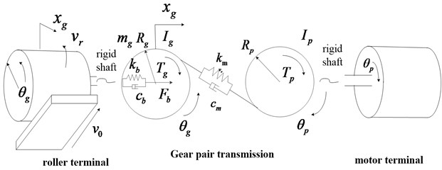
Ip, Ig are the rotational inertia of the input and the load after centralized mass, respectively. Tp, Tg are the input torque and the load torque, respectively. Since the input torque is volatile, its general form is Tp=Ta+Tbcos(ωˉt). θp, θg are the vibratory angular displacements of the input and the load, respectively. cm, km are the meshing damping coefficient, the meshing stiffness, respectively. Rp, Rg are the base radius of the input and the load, respectively. cb, kb are the bearing damping and the bearing stiffness on the driven shaft, respectively. Fb is the force between the bearing and the driven gear on the drive shaft mg, xg are the mass of driven gear, the horizontal displacement of the load center, respectively vr, v0 are the roller linear speed, the stable workpiece speed, respectively. Ff is the friction between the roller and the workpiece.
In the actual working process of rolling mill, the roller is not often in contact with the workpiece directly, and it is necessary to do some lubrication. So, there is a lubricant film between the roller and the workpiece, and the friction force is a kind of lubrication friction force. Studies have shown that there is a correspondence between the friction coefficient and the thickness of the oil film. It can be affected by a variety of factors, such as the rolling speed, cold reduction ratio, the rolling out entry tension and so on. Base on the theory of fluid mechanics and Hill's formula, simplified the dynamics process and emphasized the influence of the lubricant viscosity coefficient η and the speed of the roll line vr, the model of oil film thickness under certain conditions can be simplified as:
Among them, b0, c0 are the corresponding coefficients.
In the rolling process, the corresponding data of film thickness and friction factor can be obtained through appropriate measuring and calculating, and the expression of the friction factor can be acquired by fitting the data. Expressing the friction coefficient in the form of index, the friction coefficient can be described as:
where, a0, a, b are the liquid friction coefficient, the dry friction coefficient, the corresponding coefficient of the friction, respectively. When the roller is in horizontal vibration, the linear speed of the roller vr can be expressed as:
where v0 is the stable workpiece speed; ˙xg is the horizontal vibration speed. Substituting Eq. (3) into Eq. (2) and performing Taylor expansion, expanding retention in first several items have:
where d=bη, and μ0=ae-dv0+c is the coefficient of friction when the rolling speed is v0. At this point the friction between the roller and the workpiece is:
where Fl represents the rolling force.
According to the Newton’s law, the dynamic equation of the system is:
The transmission error of the linear displacement is defined as:
Substituting Eq. (6) with the linear displacement transfer error z, and considering the friction force Ff in the formula, further simplified results can be expressed as:
where me=IpIg/(IpR2g+IgR2p), F1=Ta/Rp=Tg/Rg, F2=meRpTb/Ip.
Eq. (8) is the dynamics equation of rolling mill main drive system, which takes horizontal-torsional coupled vibration, lubrication friction and other factors into account. The dynamic behavior of rolling mill is very complex. The research shows that there is obvious horizontal chatter in the rolling process, and source of horizontal vibration is a tribological behavior between the coexistence of fluid lubrication and dry friction motion in rolling interface. Thus, taking the roller horizontal vibration and torsion vibration coupling effect into account, the model is built. Then the friction factor between roller and workpiece is analyzed in detail. Regarding the friction as the main factor, the coupling vibration of rolling mill is analyzed and the influence of parameter variation on vibration buckling is given. It can provide relative guidance for the design of actual system. In the following, the friction coefficient d would be taken as the main research parameter to analyze dynamic behavior of rolling mill.
3. Static bifurcation analysis of high dimensional nonlinear rolling mill system
Selecting z0 as the nominal scale, and letting:
k1=1,P1=F1(z0meω21),P2=F2(z0meω21),ζ2=cb(2mgω1),ξ3=cm(2mgω1),
k2=ω22ω21,k3=km(mgω21),P3=Fb(mgz0ω21),,P4=Fl(a0+μ0)(mgz0ω21),
α1=dω1,α2=12d2ω21,α3=16d3ω13
Thus, the dimensionless system model can be expressed as:
Lettingx1=y1, x2=˙y1, x3=y2, x4=˙y2, and the state equation of the system can be expressed as:
=(x2-(k1+k3)x1-2(ζ1+ζ3)x2-k2x3-(2ζ2-α1P4)x4-α2P4x24+α3P4x34+P1+P2cos(Ωt)+P3-P4x4-k3x1-2ζ3x2-k2x3-(2ζ2-α1P4)x4-α2P4x24+α3P4x34+P3-P4),
where x=(x1,x2,x3,x4).
3.1. Lyapunov-Schmidt reduction
Ignoring the influence of the external excitation, Eq. (10) becomes autonomous system.
Let:
l1=-α2P4,l2=α3P4,l3=P3-P4,a2=-k3,b2=-2ζ3.
The equation of motion can be expressed as follows:
Then Eq. (11) can be expressed as:
where X=(x1,x2,x3,x4)T are the state variables of the dynamic system and f(X)=(f1,f2,f3,f4)T are the corresponding nonlinear vector functions.
At the equilibrium point ˉX, Eq. (12) satisfies:
Letting Df(ˉX) represent the Jacobian matrix of f(X) at the equilibrium point, the Lyapunov stability is dependent on the eigenvalues of the Jacobian matrix. The Jacobian matrix Df(ˉX) can be expressed as:
The value of the determinant is:
There is a zero eigenvalue when a1d1+2a1l1x4+3a1l2x24+a1c1-a2c1=0, and L is a singular matrix.
It can be known that dimN(L)=1. Letting v0 represent a basis vector of null space N(L), through calculating, v0=(-c1/a1,0,1,0). The adjoint operator of L is the conjugate transpose matrix L*. Since L is a real matrix, the conjugate transpose matrix L* is also a real matrix, and satisfies L*=LT, we can obtain that dimN(L*)=1 since L is a Fredholm operator with zero index. One basis vector v1=(a1b2/a2-b1,1,a1e/a2-a2e/a2,-a1/a2) of N(L*) is obtained by calculating, where e=d1+2l1x4+3l2x24. So, the four-dimensional Euclid space R4 can be decomposed as follows:
Defining the projection operator and the complementary projection operator as:
Then the equation can be expressed as:
Eq. (19) is equivalent to:
where v∈N(L)=span(v0), w∈M. According to the definition of inner product in Euclid space, (I-P)f(v+w,l2)=0 is equivalent to:
Then, the following equation is obtained:
Sincea1d1+2a1l1x4+3a1l2x24+a1c1-a2c1=0, rewriting this equation and substituting it into Eq. (22), we have:
where
C=8a21d1l1a2(a1-a2)-4a1l1a2+8c1l1,
D=F+b1+b2+6l3-a1b1+a1b2-a2b1-a1a2+a21b1a2-2a1d21a1-a2-2a1d1a2+2a21d21a2(a1-a2)+1.
Eq. (23) is a quartic algebraic equation and any univariate equation with a higher order can eliminate the second highest item by a proper transformation.
3.2. Singularity analysis
Define a new state variable m=x4, then the bifurcation equation can be written as:
where α, β are the open fold parameters of the bifurcation equation, m, n are the physical parameters of the system, respectively.
Selecting g0(m,n)=m4+n as the Golubitsky-Schaeffer normal form, according to recognition condition, the necessary and sufficient condition for G(m,n,α,β) to be a versal unfolding of g0(m,n)=m4+n is:
where A is, a matrix constructed by some partial derivatives of g and G, it can be expressed as:
Thus:
so g0(m,n)=m4+n is a 2-parameter unfolding and α, β are the unfolding parameter.
The topology of Eq. (24) and the effects of the open fold parameters on the bifurcation behavior will be studied by singularity theory.
The following point sets are obtained based on the definition of the transition set:
Ⅰ: Bifurcation point set:
Ⅱ: Lag point sets:
H2={(α,β)|G=Gm=Gmm=0}={(α,β)|α+43β√-β6=0,β≤0}.
Ⅲ: Double limits point set:
Ⅳ: Transition set:
The transition set Σ is shown in Fig. 2.
Fig. 2Transition set
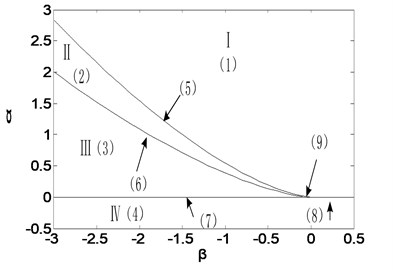
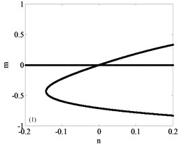
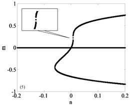
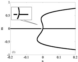
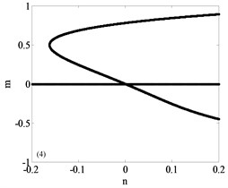
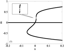
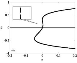
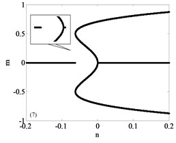
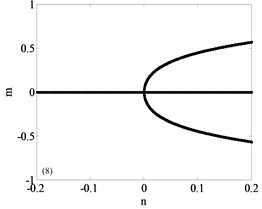
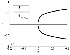
It can be seen that the unfolding parametric space α-β is divided into four sub regions by Σ. The bifurcation diagrams of each subregion and its boundary are shown in Fig. 3, a total of nine parts with Fig. 3(a)-(i) including the boundary. Among them, Fig. 3(a)-(d) are four different bifurcation regions divided by the transition set and Fig. 3(e)-(i) are bifurcation curves in the transition set. The topology of each sub region and its boundary are shown in Fig. 3. It can be seen from Fig. 3 that each sub region and its boundary have different bifurcation forms, and the system vibration mode will change when the unfolding parameters pass by the transition set.
Fig. 3Bifurcation diagram
a)
b)
c)
d)
e)
f)
g)
h)
i)
4. Hopf bifurcation analysis of high dimensional nonlinear rolling mill system
4.1. The equilibrium point analysis
In last section, the main drive system of rolling mill can be expressed as:
The equilibrium point of the Eq. (27) can be transferred to the coordinate origin by simple linear transformation. Coordinate translation does not change the dynamic characteristics, so it is of significance to study the dynamic characteristics of the system equilibrium point at the origin point. When the equilibrium point is transformed to the coordinate origin, the Eq. (13) can be turned into the following equation:
After linearizing, the Jacobian matrix at the origin can be expressed as
The characteristic equation of the J(x0,α2) is:
where:
+a1d1-a2d1p4=a1c1-a2c1.
It is easy to verify that the characteristic polynomial of Eq. (30) is equivalent to:
where:
Therefore, the Eq. (31) can be written as the following two equations:
Further, letting:
Fixing other system parameters as constants, when the friction coefficient d changes, the characteristic root of Eq. (30) has two important distributions:
Situation 1: when Δ1<0, r1>0, r2=0, s2>0, Eq. (36) has a pair of conjugate complex roots with negative real parts, and Eq. (37) has a pair of pure imaginary roots.
Situation 2: when Δ2<0, r2>0, r1=0, s1>0, Eq. (36) has a pair of pure imaginary roots, and Eq. (37) has a pair of conjugate complex roots with negative real parts.
4.2. Hopf bifurcation analysis
The friction condition has great influence on the dynamic behavior of rolling mill system. So, friction coefficient d is selected as a major parameter to analyze dynamic characteristics. The Situation 1 and Situation 2 all show that characteristic Eq. (30) has a pair of pure imaginary roots and a pair of conjugate complex roots with negative real parts. When the roots satisfy the two situations mentioned above, Hopf bifurcation is very likely to occur.
In order to find the Hopf bifurcation point and prove the existence of limit cycles, in general, we can calculate all the eigenvalues of Jacobian matrix J(x0,d), and then judge whether characteristic roots pass through the imaginary axis with the change of parameters. But the amount of calculations is very large and it is difficult to write the analytic expression of characteristic roots. Thus, the Hurwitz determinant is used to determine the existence of the Hopf bifurcation.
The characteristic equation of matrix J(x0,d) is:
where:
where Δ'i are the Hurwitz determinants. Select d=d* as a Hopf bifurcation point, the conditions of Hopf bifurcation are:
Take k1=1, k2=1, k3=0.6, ζ1=0.38, ζ2=0.38, ζ3=0.09, P3=1, P4=1. Hopf bifurcation occurs at d*=1.2324.
Supposing that the pure imaginary roots are ±ω0i, U and W are left and right normalized characteristic vectors of ω0i, respectively:
Letting:
+UfxxW*[A(0)-2iω0I]-1fxxWW),
where W* is conjugate complex of W, A(0)=A(x0,d)|d=d*:
The stability of bifurcating periodic solutions is decided by the sign of ρ. With d*=1.2324, ρ=-0.0900<0 can be obtained by calculation. Bifurcating periodic solutions aren’t asymptotical stable when ρ<0. The results show that it is a subcritical bifurcation point.
4.3. Numerical simulation
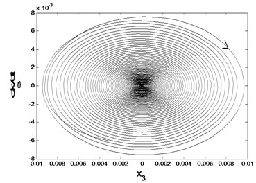
Numerical Simulation of the dynamical behavior is made near the bifurcation point. For subcritical bifurcation, when d=1.2100<d*. It can be known that the equilibrium point is asymptotically stable from Fig. 4. The unstable periodic motion may occur in the region of d=1.2280.
Fig. 4Asymptotic stability of the equilibrium point
a) The phase diagram
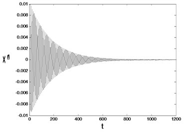
b) The time history
Fig. 5Time history responses and phase diagram with d=1.2280 and initial values are a) [0.01 0.01 0.01 0.01], b) [0.12 0.12 0.12 0.12]
![Time history responses and phase diagram with d=1.2280 and initial values are a) [0.01 0.01 0.01 0.01], b) [0.12 0.12 0.12 0.12]](https://static-01.extrica.com/articles/17493/17493-img14.jpg)
a1) The phase diagram
![Time history responses and phase diagram with d=1.2280 and initial values are a) [0.01 0.01 0.01 0.01], b) [0.12 0.12 0.12 0.12]](https://static-01.extrica.com/articles/17493/17493-img15.jpg)
a2) The time history
![Time history responses and phase diagram with d=1.2280 and initial values are a) [0.01 0.01 0.01 0.01], b) [0.12 0.12 0.12 0.12]](https://static-01.extrica.com/articles/17493/17493-img16.jpg)
b1) The phase diagram
![Time history responses and phase diagram with d=1.2280 and initial values are a) [0.01 0.01 0.01 0.01], b) [0.12 0.12 0.12 0.12]](https://static-01.extrica.com/articles/17493/17493-img17.jpg)
b2) The time history
Initial values have a certain influence on the trajectory. When initial point is [0.01 0.01 0.01 0.01], which is close to the equilibrium point, Fig. 5(a1), (a2) show that time history responses are stable and phase diagram is stable focus. When initial point is [0.12 0.12 0.12 0.12], which is far away from the equilibrium point, Fig. 5(b1), (b2) show that time history responses are unstable and phase diagram gradually expands away from a certain limit cycle. Region of attraction on initial point can be obtained by numerical simulation. In the current parameter system, when initial point exceeds [0.09 0.09 0.09 0.09], the time history responses will be unstable.
When d=1.2432>d*, the equilibrium point of the system is unstable as shown in Fig. 6, in which case the roller loses its stability and self-oscillation can be generated.
Fig. 6Asymptotic stability of the equilibrium point
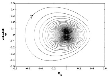
a) The phase diagram
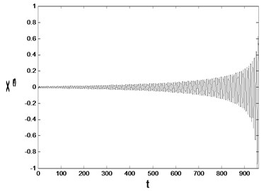
b) The time history
In summary, the system shows a complex dynamic behavior. It can be known that the friction coefficient d and the initial condition of the system are directly related to the stability of the system. When the value of friction coefficient d is much smaller than the bifurcation point, the system is asymptotically stable; when the friction coefficient d near the bifurcation point d*=1.2324, the stability of the system is mainly affected by the initial values. When the initial values are close to the equilibrium point, the system is stable; and the stability becomes worse when the initial value is far away from the equilibrium point. When the value of friction coefficient d is larger than the value of bifurcation parameter, the system is divergent, and the phenomenon of the self-excitation oscillation may occur. In the vicinity of the bifurcation point, the system may have a violent shock and even lead to complex dynamic phenomena. These phenomena should be avoided in the actual production process, so as to ensure the smooth running of the whole rolling mill system.
5. Conclusions
In this paper, a torsional-horizontal coupling vibration dynamic equation of rolling mill system is established to analyze the bifurcation characteristics. For the four-dimensional dynamic equation, firstly, the dimension is reduced by Lyapunov-Schmidt reduction method, the topological structure of the system static bifurcation is obtained by singularity analysis, and the parameter condition, which makes the system stable, is given. Then the friction coefficient d is selected as the bifurcation parameter, the dynamic Hopf bifurcation of the system is studied, and the dynamic behavior of the system is verified by numerical simulation. The results show that the system may be unstable when the friction coefficient d changes around the bifurcation point. These phenomena should be avoided in the actual production process to ensure the safe operation of the whole system. It provides a theoretical guide for the study of the horizontal-rotational coupling mechanical vibration.
References
-
Ali Heidari, Mohammad Forouzan R. Optimization of cold rolling process parameters in order to increasing rolling speed limited by chatter vibrations. Journal of Advanced Research, Vol. 4, Issue 1, 2013, p. 27-34.
-
Liu H., Zhu Z., Shi P. Stability analysis of a relative rotation time-delay nonlinear dynamic system. Acta Physica Sinica, Vol. 59, Issue 10, 2010, p. 6770-6777.
-
Shen Y., Yang S., Li C., et al. Dynamic analysis of a nonlinear system under semi-active control. Journal of Vibration Engineering, Vol. 18, Issue 2, 2005, p. 219-222.
-
Dong J., Shen Y., Yang S. Main resonance of duffing-van der pol system to multi-frequency excitations. Journal of Shijiazhuang Railway Institute, Vol. 19, Issue 1, 2006, p. 62-66.
-
Li S., Yang S. Sub-harmonic resonance and singularity of a nonlinear vehicle suspension system. Journal of Vibration Engineering, Vol. 20, Issue 2, 2007, p. 168-173.
-
Gao G., Yang S., Chen E., et al. One local bifurcation of nonlinear system based on magnetorheological damper. Acta Mechanica Sinica, Vol. 35, Issue 5, 2004, p. 564-568.
-
Shen Y., Yang S., Liu X. Nonlinear dynamics of a spur gear pair with time-varying stiffness and backlash based on incremental harmonic balance method. International Journal of Mechanical Sciences, Vol. 48, Issue 11, 2006, p. 1256-1263.
-
Shen Y., Yang S., Pan C., et al. Nonlinear dynamics of a spur gear pair with time-varying stiffness and backlash. Journal of Low Frequency Noise Vibration and Active Control, Vol. 23, Issue 3, 2004, p. 179-187.
-
Li X., Hou J. Bursting phenomenon in a piecewise mechanical system with parameter perturbation in stiffness. International Journal of Non-Linear Mechanics, Vol. 81, 2016, p. 165-176.
-
Shi P., Ji Z., Liu B., et al. Nonlinear dynamics of torsional vibration for rolling mill’s main drive system under parametric excitation. Journal of Iron and Steel Research International, Vol. 20, Issue 1, 2013, p. 7-12.
-
Liu G., Di H., Zhou C., et al. Tension and thickness control strategy analysis of two stands reversible cold rolling mill. Journal of Iron and Steel Research International, Vol. 19, Issue 10, 2012, p. 20-25.
-
Liu S., Liu B., Ye K., et al. Hopf bifurcation and stability of periodic solutions in a nonlinear relative rotation dynamical system with time delay. Acta Physica Sinica, Vol. 59, Issue 1, 2010, p. 38-43.
-
Yang X., Li Q., Tong C., et al. Vertical vibration model for unsteady lubrication in rolls-strip interface of cold rolling mills. Advances in Mechanical Engineering, Vol. 4, Issue 12, 2012, p. 1432-1437.
-
Hou D., Peng R., Liu H. Analysis of vertical-horizontal coupling vibration characteristics of rolling mill rolls based on strip dynamic deformation process. Shock and Vibration, Vol. 2014, Issue 2, 2014, p. 1-11.
-
Hou D., Zhu Y., Liu H., et al. Research on nonlinear vibration characteristics of cold rolling mill based on dynamic rolling force. Journal of Mechanical Engineering, Vol. 49, Issue 14, 2013, p. 45-50.
-
Xu Y., Tong C., Yue G., et al. Coupling Dynamic model of chatter for cold rolling. Journal of Iron and Steel Research International, Vol. 17, Issue 12, 2010, p. 30-34.
-
Zhang R., Chen Z., Wang F. Study on parametrically excited horizontal nonlinear vibration in single-roll driving mill system. Journal of Vibration and Shock, Vol. 29, Issue 6, 2010, p. 105-108.
-
Sun J., Yan P., Liu H. Non-linear vibration and stability of moving strip with time-dependent tension in rolling process. Journal of Iron and Steel Research International, Vol. 17, Issue 6, 2010, p. 11-15.
-
Zeng L., Zang Y., Gao Z. Effect of rolling process parameters on stability of rolling mill vibration with nonlinear friction. Journal of Vibroengineering, Vol. 18 Issue 2, 2016, p. 1288-1296.
-
Liu H., Zhang J., Mi K., et al. Simulation on hydraulic-mechanical coupling vibration of cold strip rolling mill vertical system. Advanced Materials Research, Vol. 694-697, 2013, p. 407-414.
-
Senjanović I., Ćatipović I., Tomašević Coupled horizontal and torsional vibrations of a flexible barge. Engineering Structures, Vol. 30, Issue 1, 2008, p. 93-109.
Cited by
About this article
Project supported by the National Natural Science Foundation of China (Grant No. 61673334, 51575472). and supported by the National Natural Science Foundation of Hebei Province (Grant No. E2017203144).

