Abstract
This paper aims at improving the performance of tracked ambulance nonlinear vibration reduction system by the structure optimization design. The structure optimization focuses on the stretcher base. Two structure optimization schemes are proposed based on the mechanism of dynamic vibration absorber (DVA), namely, the linear and nonlinear structure optimization schemes. The linear structure optimization scheme is finally adopted by comparison of two schemes under random vibration, and the performance of linear scheme is also validated under shock vibration. Then the global sensitivity analysis method is applied to calculate the parameter sensitivity of nonlinear vibration reduction system. At last, the nondominated sorting genetic algorithm II (NSGA-II) is used to optimize the performance of the nonlinear vibration reduction system. It shows the vibration energy of the supine human body on stretcher is reduced after above studies, which proves the validity and feasibility of the structure optimization schemes proposed, and the optimization studies applied in this paper.
1. Introduction
It is clear that the harsh vibration environment can cause the secondary injury to the sick and wounded in ambulance transit. To reduce the unnecessary injury, the vibration reduction system is usually installed on the ambulance, and this method is applied widely in engineering. The fine performance of vibration reduction system can reduce the unnecessary injury in transit. Therefore, the structure optimization for tracked ambulance nonlinear vibration reduction system has important practical significance. In the previous study, the performance of tracked ambulance nonlinear vibration reduction system has been studied and improved [1]. However, the structure improvement is not covered in the study. So the structure optimization of nonlinear vibration reduction system is carried out in this paper to improve its vibration reduction performance further.
Structure optimization is an advanced subject in engineering structure design at present and has a broad application in engineering practice. It can be divided into size optimization, shape optimization and topology optimization based on the type of design variable [2, 3]. Due to the significance of structure optimization, the depth and breadth of researches in this field have been continuously expanded, and many achievements have been made. Dong, Zhao et al. [4] discussed the theory, approach and present situation of modern mechanical optimization design from two aspects of setting up mathematical models and solving algorithm, and put forward several scientific questions that should be further studied in the modern mechanical optimization design. Liu, Ma et al. [5] optimized the structure of rubber absorber by using BP (Back Propagation) neural network and finite element method, and obtained the optimal design parameters of rubber absorber. Zhang, Kang [6] investigated the topology optimization of piezoelectric actuator/sensor coverage attached to a thin-shell structure, the result of which can be used for providing useful guidance to the layout design of the actuator/sensor layers attached to a thin-shell structure subject to dynamic excitations. Vicente, Picelli et al. [7] proposed a topology optimization method for the frequency response of a multiphysics system involving fluid-structure interaction and took several examples to demonstrate the validity of the method proposed. Caresta and Kessissoglou [8] investigated the reduction of far-field radiated sound pressure from a submarine using design modifications to the propeller-shafting system attachment to the hull. It showed that the structure improvement applied gave a significant reduction in the low frequency structure-borne radiated sound.
The structure of this paper is as follows: Section 2 is devoted to introduce tracked ambulance nonlinear vibration reduction system. Two structure optimization schemes based on the mechanism of DVA are proposed in Section 3, then in Section 4, the comparison of two optimization schemes is carried out under random vibration, and the linear optimization scheme is finally adopted. The performance of linear scheme is also validated under shock vibration. After structure optimization, the parameter sensitivity analysis and parameter optimization for nonlinear vibration reduction system are carried out in Section 5 and Section 6. It is shown that the performance of nonlinear vibration reduction system is improved by completing above studies. Finally, in Section 7, the basic findings of this work are summarized.
2. The introduction of tracked ambulance nonlinear vibration reduction system
We select the nonlinear vibration reduction system of a tracked ambulance [9] as the research object. The tracked ambulance is mainly used in harsh environment and consists of the front vehicle and rear vehicle. The front vehicle is the cab. The sick and wounded is placed in the rear vehicle. Because the motion of the rear vehicle plays a greater effect on the sick and wounded than that of the front vehicle, this paper will only study the vibration of rear vehicle. The rear vehicle of tracked ambulance is shown in Fig. 1.
Fig. 1The rear vehicle of tracked ambulance: (1) carriage, (2) stretcher base, (3) zero stiffness shock absorbers, (4) rubber damping shock absorbers, (5) chassis
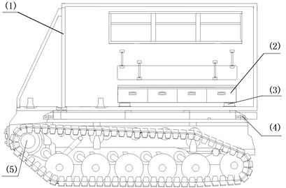
Fig. 2The power spectral density (PSD) of vertical vibration acceleration of stretcher base
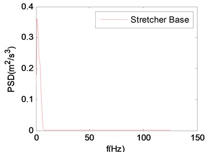
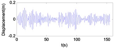
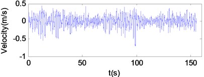
As shown in Fig. 1, the tracked ambulance nonlinear vibration reduction system is a two levels system. The first level is rubber damping shock absorbers which can reduce the vibration energy transmitted from chassis to carriage; the second level is zero stiffness shock absorbers which can reduce the vibration energy transmitted from carriage to stretcher base. In the previous study, we have already conducted a field vibration test on the tracked ambulance and obtained the vibration data of stretcher base, carriage and chassis [10]. The PSD of vertical vibration acceleration of the stretcher base on the rough road (15 km/h) is shown in Fig. 2. The vertical vibration displacement and speed of the chassis on the rough road (15 km/h) are shown in Fig. 3. All following studies are carried out in the condition of the rough road (15 km/h).
Fig. 3The vertical vibration displacement and speed of chassis.
3. The structure optimization schemes of nonlinear vibration reduction system
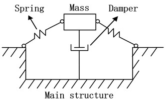
The novelty of this paper is to propose two structure optimization schemes, using the mechanism of DVA for reference. DVA [11-15] consists of mass-spring-damper systems attached to the main structure and is widely used in engineering for reducing vibrations. The mass that is attached to main structure by the spring and damper can absorb the vibration energy of main structure through the rational parameter setup of mass, spring and damper. Most often, the mass is lightweight. Fig. 4 is the structure of a nonlinear DVA.
Fig. 4The nonlinear DVA
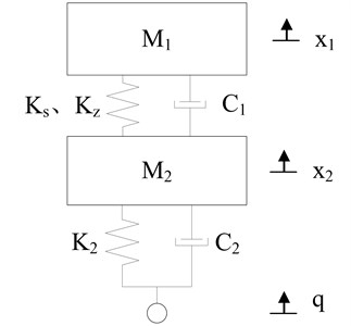
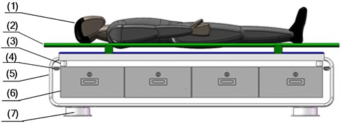
The structure optimization for nonlinear vibration reduction system focuses on the stretcher base which is comprised of stretcher and storage box. Before structure optimization, zero stiffness shock absorbers, stretcher base and supine human body are strung together as shown in Fig. 5. The supine human body is connected to the stretcher base with no spring and damper, so they can be considered as a whole which is simply referred to as “stretcher base” later. Due to the fact that vertical vibration has a greater impact on the comfort of human body, two horizontal directions are neglected and the model of nonlinear vibration reduction system is set up in Section 3.1, as shown in Fig. 6. By using the mechanism of DVA for reference, we separate the stretcher and storage box, and install a steel frame between zero stiffness shock absorbers and stretcher. The storage box is hung in the middle of steel frame by spring and damper, forming a “DVA”. The supine human body and steel frame are connected to the stretcher with no spring and damper, so they can be considered as a whole which is simply referred to as “stretcher” later.
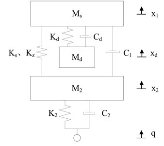
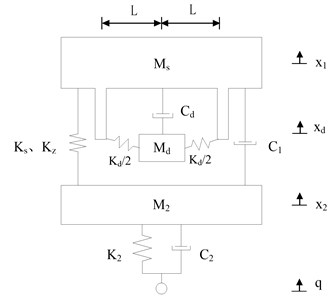
Based on this structure design, two structure optimization schemes are proposed in Section 3.2 and Section 3.3. In scheme 1, the storage box is hung in a linear manner as shown in Fig. 7; in scheme 2, the storage box is hung in a nonlinear manner as shown in Fig. 9. By also only retaining the vertical direction, the models of nonlinear vibration reduction system after structure optimization are set up as shown in Fig. 8 and Fig. 10. In addition, when setting up the kinetic differential equations of nonlinear vibration reduction system, we use the positive and negative stiffness parallel model, and linear model to represent the zero stiffness shock absorbers and rubber damping shock absorbers [9]. In this paper, all the models are considered as multiple-rigid-body model with no elasticity.
3.1. The stretcher base before structure optimization
The kinetic differential equations of the vibration model in Fig. 6 are as follows:
where M1 and M2 are the masses of stretcher base and carriage; Ks, Kz, C1 are the linear stiffness, cubic nonlinear stiffness and linear damper of zero stiffness shock absorbers; K2, C2 are the linear stiffness and damper of rubber damping shock absorbers; x1, x2, q are the vibration displacement of stretcher base, carriage and chassis. The values of above parameters are as follows: M1=180 kg, M2= 2000 kg, Ks=163499 N/m, Kz=15168.3 N/m, C1=1849.42 N·s/m, K2= 1586472 N/m, C2=28588.3 N·s/m.
Fig. 5The Stretcher base before structure optimization: (1) supine human body, (2) stretcher, (3) storage box, (4) zero stiffness shock absorbers
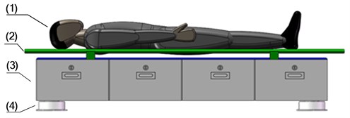
Fig. 6The model of nonlinear vibration reduction system before structure optimization
3.2. The structure optimization scheme 1
The kinetic differential equations of the vibration model in Fig. 8 are as follows:
Fig. 7The structure optimization scheme 1: (1) supine human body, (2) stretcher, (3) spring and damper, (4) steel frame, (5) storage box, (6) zero stiffness shock absorbers
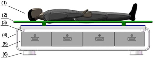
Fig. 8The model of nonlinear vibration reduction system after structure optimization (Scheme 1)
3.3. The structure optimization scheme 2
In Fig. 10, the two springs that carry the storage box produce an essentially nonlinear stiffness nonlinearity of the third degree [11]. So, the kinetic differential equations of the vibration model in Fig. 10 are as follows:
Fig. 9The structure optimization scheme 2: (1) supine human body, (2) stretcher, (3) damper, (4) spring, (5) steel frame, (6) storage box, (7) zero stiffness shock absorbers
In Fig. 8 and Fig. 10, Ms and Md are the masses of stretcher and storage box; Kd, Cd are the stiffness and damper by which the storage box and steel frame are connected; x1, xd, x2, q are the vibration displacement of stretcher, storage box, carriage and chassis. The original parameters of nonlinear vibration reduction system remain unchanged after structure optimization, namely M2, Ks, Kz, C1, K2, C2.
Because the stretcher and storage box are installed in a narrow carriage, their vertical installation size that is mainly determined by the vertical size of storage box should be as small as possible. However, installing steel frame will inevitably bring an increase in the vertical installation size of the stretcher and storage box. In order to offset the increase in the vertical installation size of the stretcher and storage box, we reduce the vertical size of storage box. This will bring a decrease in the mass of storage box. The mass of storage box reduces from 105 kg before structure optimization to 80 kg after structure optimization. The mass of steel frame is set to 45 kg. So the masses of stretcher and storage box after structure optimization are given out as follows: Ms= 120 kg, Md=80 kg. Kd and Cd are the undetermined parameters.
Fig. 10The model of nonlinear vibration reduction system after structure optimization (Scheme 2)
4. The comparison of structure optimization schemes
In the following, the weighted root mean square values of vertical vibration acceleration of stretcher and storage box after structure optimization, and stretcher base before structure optimization are represented by WRMSMs, WRMSMd and WRMSM1 respectively. In the following studies, the improved partitioning and dimensional increment precise integration method will be used many times to calculate the output of the vibration reduction system. The method is described in detail in reference [1] and needs not be repeated in this paper.
To determine the final structure optimization scheme, two schemes proposed in section 3 are compared in this section. First, the variation ranges of Kd and Cd are given in Table 1 according to the characteristics of each structure optimization scheme, and the uniform samplings of Kd and Cd are performed in variation ranges. Then, since the purpose of this paper is to reduce the vibration energy of the supine human body on stretcher, WRMSMs is taken as the optimization object which is calculated by the improved partitioning and dimensional increment precise integration method under different combinations of Kd and Cd. The value distributions of optimization objects of two structure optimization schemes are shown in Fig. 11 and Fig. 12, and compared. At last, the final structure optimization scheme is selected based on the result of comparison of two schemes.
Table 1The variation ranges of Kd and Cd
Optimization Schemes | Parameters | Lower limit | Upper limit |
Scheme 1 | Kd (N/m) | 16000 | 400000 |
Cd(N·s/m) | 100 | 40000 | |
Scheme 2 | Kd (N/m) | 1×10⁶ | 2×10⁹ |
Cd(N·s/m) | 100 | 40000 |
Fig. 11 shows that the minimum of WRMSMs can be found when Kd and Cd are small. As Kd and Cd get larger, WRMSMs becomes smooth and eventually close to WRMSM1 before structure optimization. Fig. 12 shows that the minimum of WRMSMs also can be found when Kd and Cd are small. When Cd is large, WRMSMs is close to WRMSM1 before structure optimization. Along with the decrease of Cd, WRMSMs decreases slowly at the beginning, and then increases markedly after Cd is smaller than a certain critical value. To observe the impact of each structure optimization scheme on the performance of nonlinear vibration reduction system more clearly, WRMSM1 before structure optimization, the minima of WRMSMs in Fig. 11 and Fig. 12 as well as the Kd and Cd of minima are shown in Table 2.
Fig. 11The structure optimization scheme 1
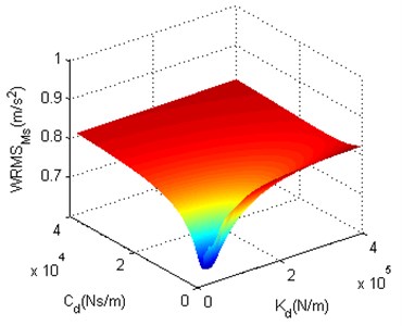
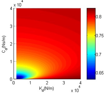
Fig. 12The structure optimization scheme 2
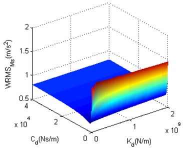
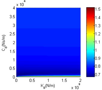
Table 2Calculation results
Optimization schemes | Kd(N/m) | Cd (N·s/m) | WRMSMs(m/s2) |
Before structure optimization | – | – | 0.8251 (WRMSM1) |
Scheme 1 | 31400 | 700 | 0.6328 |
Scheme 2 | 3000000 | 1100 | 0.6675 |
First, Table 2 shows that two structure optimization schemes have both achieved good results, and their WRMSMs are significantly decreased compared with WRMSM1 before structure optimization. The drop of scheme 1 is 23.3 % and obviously greater than 19.1 % of scheme 2, which proves that scheme 1 works better than scheme 2. Then, as can be seen from Table 2, the Kd of scheme 1 and scheme 2 are 31400 N/m and 3000000 N/m respectively. A linear spring of 31400 N/m with a static load of 80 kg can produces 25 mm deformation and a cubic nonlinear spring of 3000000 N/m with a static load of 80 kg can produce 64 mm deformation. The vertical installation size of scheme 2 is obviously greater than that of scheme 1. Due to the fact that the stretcher and storage box are installed in a narrow carriage, it is better to choose the scheme with a smaller installation size. Based on the two reasons above, scheme 1 is chosen as the final structure optimization scheme. Moreover, the Kd and Cd of scheme 1 are taken into the model to calculate WRMSMd whose value is 0.9811 m/s2. WRMSMd is obviously greater than WRMSMs and WRMSM1. This indicates that the reduced vibration energy of stretcher is transferred to the storage box, which proves the validity of the structure optimization scheme proposed in this paper. The PSDs of stretcher base before structure optimization and stretcher after structure optimization are shown in Fig. 13, where the stretcher is installed in the form of scheme 1, and the PSD of ASO is calculated by using the Kd and Cd of scheme 1. In Fig. 13, ASO and BSO stand for “After Structure Optimization” and “Before Structure Optimization” respectively.
Due to the fact that the tracked ambulance is mainly used in harsh environment and often excited by the potholes and bumps, the sick and wounded often suffer from shock vibration in transit. Thus it is necessary to compare the performances of the vibration reduction system before and after structure optimization under shock vibration. In this paper, the acceleration pulse is taken as the systematic excitation and the half sine wave is used to represent the vibration acceleration of chassis. According to the wording condition of tracked ambulance, the peak and duration of the half sine wave are 5 g and 0.01 s respectively. The calculation equation of the vibration acceleration of chassis is as follows:
By introducing new variables x1q=x1-q, x2q=x2-q and substituting x1q, x2q into Eq. (1) and Eq. (2), Eq. (1) and Eq. (2) are changed into the following form:
By introducing new variables xdq=xd-q and substituting xdq, x1q, x2q into Eq. (3) Eq. (4) and Eq. (5), Eq. (3), Eq. (4) and Eq. (5) are changed into the following form:
+Cd(˙x1q-˙xdq)=-M1¨q,
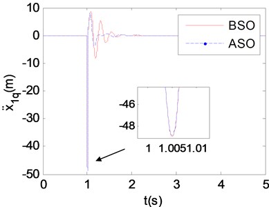
In Eq. (10) to Eq. (14), xdq, x1q and x2q represent the relative displacements between storage box and chassis, stretcher/stretcher base and chassis, carriage and chassis respectively. Then the improved partitioning and dimensional increment precise integration method is used to calculate the response of vibration reduction system before and after structure optimization. The relative displacements and accelerations between stretcher/stretcher base and chassis are shown in Fig. 14 and Fig. 15.
Fig. 13 shows that the vibration energy of stretcher within 2-7 Hz is obviously decreased after structure optimization (See detail view), and human body is precisely sensitive to the vibration in this frequency range. Fig. 14 shows that the biggest relative displacement after structure optimization is smaller than that before structure optimization (See detail view), and the amplitude of relative displacement after structure optimization decreases more rapidly than that before structure optimization. Fig. 15 shows that the biggest relative accelerations before and after structure optimization are almost the same (See detail view), but the amplitude of relative acceleration after structure optimization decreases more rapidly than that before structure optimization. The above studies prove that the structure optimization scheme proposed in this paper is effective and of great significance to reduce the vibration energy of supine human body on stretcher.
Fig. 13The PSDs of stretcher base and stretcher
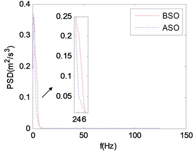
Fig. 14The relative displacement
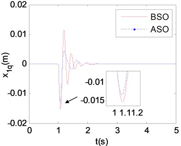
Fig. 15The relative acceleration
5. The parameter sensitivity analysis of nonlinear vibration reduction system after structure optimization
The major task of parameter sensitivity analysis is to calculate the value of parameter sensitivity and thereby obtain the importance ranking of parameters. We can filter the compute variables based on the importance ranking of parameters, hence reducing the computational effort for the following analyses. This paper chooses the Sobol method to calculate the global parameter sensitivity of the nonlinear vibration reduction system with respect to WRMSMs. There are two reasons. The first one is that the stiffness of zero stiffness shock absorbers is cubic nonlinear stiffness, and many sensitivity analysis methods cannot calculate the sensitivity of nonlinear term. The second one is that the differences of system parameters are one or more orders of magnitude. Because the vertical vibration acceleration has a great effect on the comfort of human body, this paper chooses the Sobol method as the sensitivity analysis method. The computational equation of the weighted root mean square value of vibration acceleration is:
in which f is the frequency; Sz(f) is the PSD of vibration acceleration; ω(f) is the weighted frequency function. The computational equation of ω(f) is:
The variation ranges and probability distributions of parameters must be first given out when we use the Sobol method to calculate the global parameter sensitivity. For the nonlinear vibration reduction system after structure optimization, the variations of parameters are assumed to follow the uniform distribution [16] and the variation ranges of parameters are shown in Table 3.
Table 3The variation ranges of parameters
Parameters | Lower limit | Upper limit |
Ks(N/m) | 130798.8 | 196198.4 |
Kz(N/m) | 12149.1 | 18223.6 |
C1(N·s/m) | 1479.5 | 2219.3 |
K2(N/m) | 1269177.6 | 1903766.4 |
C2(N·s/m) | 22870.6 | 34305.9 |
Kd(N/m) | 25120 | 37680 |
Cd(N·s/m) | 560 | 840 |
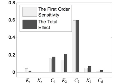
Then the Sobol method [17, 18] is applied to calculate the global parameter sensitivity of nonlinear vibration reduction system after structure optimization. Before calculating the global sensitivity indices, we must first calculate WRMSMs under random vibration, and this will be done by the improved partitioning and dimensional increment precise integration method. In calculation, the Sobol sequence sampling method [19] is applied to sample the system parameters. We conduct 10 times global sensitivity calculation whose mean is taken as the result. The detailed calculation results are shown in Table 4. For showing the results in Table 4 more intuitively, the results in Table 4 are presented in the histogram, as shown in Fig. 16.
Table 4The results of global sensitivity calculation
Parameters | Sobol method | |
First order sensitivity indices | Total effect indices | |
Ks | 0.0474 | 0.017483 |
Kz | –3×10⁻⁸ | –8.3×10⁻⁸ |
C1 | 0.15995 | 0.180941 |
K2 | 0.13439 | 0.212504 |
C2 | 0.59399 | 0.601551 |
Kd | 0.05247 | 0.069887 |
Cd | 0.01319 | 0.025465 |
The first order sensitivity index is used to evaluate the influence extent of a parameter change alone on the system output; the total effect index is used to evaluate the influence extent of a parameter change alone as well as the interaction with other parameters on the system output. The obvious difference between two indices indicates that the interaction with other parameters is great. Fig. 16 shows that the differences between two indices are all small. It indicates that no significant interactions exist among system parameters. After global sensitivity analysis, the parameters are ranked in order of the greatest importance to the least as follows: C2, C1, K2, Kd, Ks, Cd, Kz. Table 4 shows that the change of Kz has little effect on WRMSMs, so its value will not be changed in the following analyses.
Fig. 16The global parameter sensitivities of the nonlinear vibration reduction system after structure optimization
6. The parameter optimization of nonlinear vibration reduction system after structure optimization
In this paper, the nonlinear vibration reduction system is optimized regarding two object functions:
(1) WRMSMs. WRMSMs is an important index to evaluate the ride comfort of supine human body on the stretcher and should be minimized. So WRMSMs is taken as one optimization object and its calculation equation is the same with Eq. (15), namely:
(2) The relative displacement between stretcher and storage box. The relative displacement between stretcher and storage box has a great effect on the vertical installation size of stretcher and storage box. If the relative displacement is great, the vertical dimension of the steel frame that supports the stretcher and storage box also must be great. As described earlier, the carriage is relative narrow. Thus the relative displacement between stretcher and storage box should be also minimized. The root mean square value (RMS) of the relative displacement between stretcher and storage box is taken as another optimization object. Its calculation equation is as follows:
where x1d=x1-xd. After choosing the optimization objects, the NSGA-II [20] is taken as the optimization algorithm. When we use the NSGA-II to optimize two optimization objects, the variation ranges of system parameters must be first given out. The optimization parameters include the original system parameters, such as Ks, C1, K2, C2, and parameters added after structure optimization, such as Kd, Cd. Then the values of two optimization objects are calculated by the improved partitioning and dimensional increment precise integration method. Finally, the NSGA-II is applied to optimize the values of two optimization objects. For the vibration reduction system after structure optimization, the variation ranges of system parameters are shown in Table 5. Before the calculation, some required parameters for NSGA-II are given out as follows: the optimal front individual coefficient is 0.1; the size of population is 300; the maximum number of iterations is 200; the stall generation limit is 200; the tolerance of fitness function is 1×10⁻⁶. By completing the above settings, the parameter optimization is carried out.
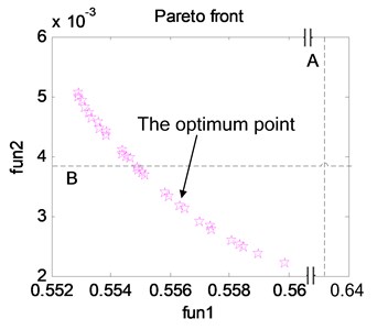
The first front individual distribution is shown in Fig. 17, and the Pareto solution set is shown in Appendix. To optimize two object functions, the point in Fig. 17 is selected as the optimum point. In Fig. 17, line A stands for the WRMSMs (Object 1) before parameter optimization whose value is 0.6328 m/s2 and line B stands for the RMS of the relative displacement between stretcher and storage box (Object 2) before parameter optimization whose value is 0.0038 m. In the Appendix, the line in bold is the results of the optimum point.
Table 5The variation ranges of parameters
Parameters | Lower limit | Upper limit |
Ks(N/m) | 100000 | 450000 |
C1(N·s/m) | 850 | 3500 |
K2(N/m) | 1000000 | 3000000 |
C2 (N·s/m) | 10000 | 45000 |
Kd(N/m) | 10000 | 50000 |
Cd (N·s/m) | 100 | 1000 |
Fig. 17The first front individual distribution.
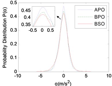
After optimization calculation, the parameters before and after parameter optimization are compared in Table 6. Then the PSDs and probability distributions of vertical vibration accelerations of the stretcher before and after parameter optimization and the stretcher base before structure optimization are compared to validate the effectiveness of parameter optimization, as shown in Fig. 18 and Fig. 19, where APO and BPO stand for “After Parameter Optimization” and “Before Parameter Optimization”. Actually, the curves of BPO and ASO are the same.
Table 6The parameters before and after parameter optimization
Parameters | Before parameter optimization | After parameter optimization |
Ks(N/m) | 163499 | 308033 |
C1(N·s/m) | 1849.42 | 3151.94 |
K2(N/m) | 1586472 | 1103289 |
C2(N·s/m) | 28588.3 | 44381.4 |
Kd(N/m) | 31400 | 32936 |
Cd(N·s/m) | 700 | 813.34 |
fun1 (m2/s) | 0.6328 | 0.5563 |
fun2 (m) | 0.0038 | 0.00316 |
Table 6 shows that WRMSMs reduces from 0.6328 m/s2 before parameter optimization to 0.5563 m/s2 after parameter optimization with a 12.1 % drop. WRMSMs after parameter optimization falls by 32.6 % compared with WRMSM1(0.8251 m/s2) before structure optimization. Table 6 also shows that the RMS of relative displacement between stretcher and storage box reduces from 0.0038m before parameter optimization to 0.00316m after parameter optimization with a 16.8 % drop. The greatest relative displacement also reduces from 0.0217 m before parameter optimization to 0.0137m with a 36.9 % drop.
Fig. 18 shows that the PSD within 2-7 Hz after parameter optimization are obviously decreased compared with those before parameter optimization and structure optimization, as shown in the detail view. More vibration accelerations after parameter optimization are concentrated near 0 m/s2 compared with those before parameter optimization and structure optimization, as shown in the detail view of Fig. 19. The probability of vertical vibration acceleration of the stretcher within –0.12 m/s2 to 0.12 m/s2 is 0.1125, increased by 8.4 % and 11.7 % compared with 0.104 before parameter optimization and 0.1007 before structure optimization. According to the above results obtained, the vibration energy of supine human body on stretcher is reduced significantly, which demonstrates the validity of parameter optimization calculation.
Fig. 18The comparison of PSDs
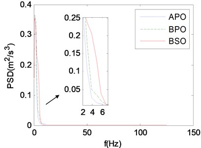
Fig. 19The comparison of probability distributions
7. Conclusions
This paper mainly accomplished three aspects of work as follows:
(1) Two structure optimization schemes were proposed based on the mechanism of DVA, and the comparison of two schemes under random vibration and shock vibration was carried out to choose the final scheme;
(2) The parameter sensitivity analysis of the nonlinear vibration reduction system after structure optimization was carried out, and the importance ranking of the system parameters was obtained;
(3) The performance of nonlinear vibration reduction system was optimized by the NSGA-II, and the vibration energy of supine human body on stretcher was reduced.
In this paper, the novelty lies in proposing two structure optimization schemes for nonlinear vibration reduction system based on the mechanism of DVA, and comparing them under different excitation conditions. By adopting and optimizing the final structure optimization scheme, WRMSMs has been decreased and the performance of tracked ambulance nonlinear vibration reduction system was further improved, which demonstrates the feasibility and validity of the structure optimization schemes. The structure optimization schemes proposed in this paper give a solution to the structure optimization for all sorts of platform with a bigger attached mass, in particular, it has a high requirement for the vibration environment.
References
-
Yang M., Xu X. X., Su W. H., et al. The dynamic performance optimization for nonlinear vibration-reduction system of the tracked ambulance. Proceedings of IMechE Part C: Journal of Mechanical Engineering Science, Vol. 229, Issue 15, 2015, p. 2719-2729.
-
Chen J. J., Che J. W., Cui M. T., et al. A review on structural dynamic optimum design. Advances in Mechanics, Vol. 31, Issue 2, 2001, p. 181-192.
-
Li F., Ling D. S. Survey of the developing in engineering structural optimization design. Journal of Engineering Design, Vol. 9, Issue 5, 2002, p. 229-235.
-
Dong L. L., Zhao Y. P., Liang L. Q., et al. Review on theory and approach of mechanical optimization design. Machine Tool and Hydraulics, Vol. 38, Issue 15, 2010, p. 114-119.
-
Liu J. R., Ma Y. M., Huang W. Optimization of an absorber based BP neural network and genetic algorithm. Mechanical Science and Technology for Aerospace Engineering, Vol. 30, Issue 8, 2011, p. 1267-1271.
-
Zhang X. P., Kang Z. Dynamic topology optimization of piezoelectric structures with active control for reducing transient response. Computer Methods in Applied Mechanics and Engineering, Vol. 281, 2014, p. 200-219.
-
Vicente W. M., Picelli R., Pavanello R., et al. Topology optimization of frequency responses of fluid-structure interaction systems. Finite Elements in Analysis and Design, Vol. 98, 2015, p. 1-13.
-
Caresta M., Kessissoglou N. J. Reduction of hull-radiated noise using vibroacoustic optimization of the propulsion system. Journal of Ship Research, Vol. 55, Issue 3, 2011, p. 149-162.
-
Yang M., Xu X. X., Su C. A study on vibration characteristics and stability of the ambulance nonlinear damping system. Abstract and Applied Analysis, DOI 10.1155/2013/501081, 2013.
-
Su C., Xu X. X., Gao Z. H., et al. Analysis on two level damping efficiency and recumbent comfort for tracked emergency ambulance. Journal of Vibration, Measurement and Diagnosis, Vol. 32, Issue 5, 2012, p. 854-869.
-
Andersen D., Starosvetsky Y., Vakakis A., et al. Dynamic instabilities in coupled oscillators induced by geometrically nonlinear damping. Nonlinear Dynamics, Vol. 67, Issue 1, 2012, p. 807-827.
-
Mohammad A., Al-Shudeifat Highly efficient nonlinear energy sink. Nonlinear Dynamics, Vol. 76, Issue 4, 2014, p. 1905-1920.
-
Samani F. S., Pellicano F., Masoumi A. Performances of dynamic vibration absorbers for beams subjected to moving loads. Nonlinear Dynamics, Vol. 73, Issues 1-2, 2013, p. 1065-1079.
-
Samani F. S., Pellicano F. Vibration reduction of beams under successive traveling loads by means of linear and nonlinear dynamic absorbers. Journal of Sound and Vibration, Vol. 331, Issue 10, 2012, p. 2272-2290.
-
Sapsis T. P., Quinn D. D., Vakakis A. F., et al. Effective stiffening and damping enhancement of structures with strongly nonlinear local attachments. Journal of Vibration and Acoustics – Transactions of the ASME, Vol. 134, Issue 1, 2012, p. 011016.
-
Akmar A. B. I., Lahmer T., Bordas S. P. A., et al. Uncertainty quantification of dry woven fabrics: a sensitivity analysis on material properties. Composite Structures, Vol. 116, 2014, p. 1-17.
-
Stephen J., Frances Y. K. Constructing Sobol sequences with better two-dimensional projections. SIAM Journal on Scientific Computing, Vol. 30, Issue 5, 2008, p. 2635-2654.
-
Salttelli A., Ratto M., Andres T., et al. Global Sensitivity Analysis. The Primer. First Edition, John Wiley and Sons Ltd., Chichester, 2008.
-
Stephen J., Frances Y. K. Constructing Sobol sequences with better two-dimensional projections. SIAM Journal on Scientific Computing, Vol. 30, Issue 5, 2008, p. 2635-2654.
-
Kalyanmoy D., Amrit P., Sameer A., et al. A fast and elitist multi-objective genetic algorithm: NSGA-II. IEEE Transactions on Evolutionary Computation, Vol. 6, Issue 2, 2002, p. 182-197.

