Abstract
In this work, some theoretical analyses, numerical simulations and experimental results on synchronization of a dual-rotors exciter are given. The exciter is made up of two rotors with eccentric masses (REMs) respectively driven by two DC motors with common axis. By adjusting the phase difference between two REMs to change the response amplitude, the decoupling between response amplitude and exciting frequency can be realized. The motion equations of the vibration system are established by using Lagrange equation, and the dimensionless coupling equations of that are obtained by applying the average method of small parameter. According to the existence condition of the zero solution of the dimensionless coupling equations, the synchronization condition of the vibration system is obtained. The stability condition of the vibration system implementing synchronization motion is acquired based on the principle of Hamilton. Through the comparison between numerical simulations and experimental results, the validity of theoretical analyses is proved, which helps the design of the dual-rotors exciter.
1. Introduction
Synchronization is a motion form which objectively exists in the natural world and the human society, as well as the fields of engineering and technology [1].
Huygens [2] is the first person who found the synchronization phenomenon in pendulum clock system. Blekhman [3-7] studied motion stability of double exciters by using the method of Poincare-Lyapunov small parameter, and first proposed the synchronization theory of exciters. Wen [1, 8-11] considered the effect of system damping on the basis of the former, and converted the motion equations of REMs into the equations of phase differences of REMs after average integral. Balthazar [12, 13] gave some comments on self-synchronization mechanisms of two non-identical exciters and four non-ideal exciters by numerical simulations. Quinn [14] studied the dynamics and synchronization under resonance case. Nijmeijer [15] studied dynamic control on synchronization from a control theory perspective. Yamapi [16, 17] studied the dynamics and synchronization of two coupled self-excited devices. Perlikowski [18] described the relation between the complete, phase and generalized synchronization of the mechanical oscillators driven by the chaotic signal generated by the driven system. Acebron [19, 20] applied the Kuramoto model to explain synchronization phenomenon in large population of phase oscillators. Tanaka [21] analyzed a large system of nonlinear phase oscillators with sinusoidal nonlinearity, uniformly distributed natural frequencies and global all-to-all coupling, which is an extension of Kuramotor’s model to second-order system.
Further research on vibration synchronization theory and broaden its application domain, in order to satisfy the demands of practical engineering, is one of the current research hotspots in the field of synchronization.
When the phase difference between two REMs in the vibration system is stable in a certain value, it will make the system work in a particular motion form [8-11]. We can apply this principle to design vibration machines, which satisfy various demands such as motion trajectory and amplitude. The rotation axes of two REMs in many articles are parallel, there is not the case that the rotation axes of two REMs are common. A novel design for small vibrotactors called the dual-rotors exciter is first presented by Miklos [22, 23], which makes it possible to produce vibrations with independently adjustable frequency and amplitude. However, for vibration equipment, synchronization is the result that vibration system automatically selects energy distribution by itself. In engineering, whatever kind of synchronization is adopted, only understand the coupling dynamic characteristic of the vibration system can reasonable limit the phase difference between two REMs.
This paper discusses the coupling dynamic characteristic of the dual-rotors exciter based on synchronization theory, and it contains the following elements: First, the motion equations of the dual-rotors exciter are established. Second, the synchronization condition and the stability condition of synchronization state are deduced. Third, numerical discussions are provided. Fourth, experiments are given. Finally, concludes this paper.
2. Dynamic model of the dual-rotors exciter
Fig. 1 illustrates the dynamic model of the dual-rotors exciter, in which springs are connected to a rigid frame. The two DC motors are installed in the rigid frame with the common axis, which drive two REMs rotating in the same direction to excite the vibration system. The frame oxy is a fixed frame, and its origin o is the equilibrium point of centroid of the rigid frame, meanwhile the frame Gx'y' is a non-rotation moving frame. The motions of the rigid frame are vibrations in x- and y- directions, denoted by x and y. Each REM rotates about its rotation axis, denoted by φ1 and φ2. m is the mass of the rigid frame. m1 and m2 are the masses of two REMs. r1 and r2 are the eccentric radiuses of two REMs. ω1 and ω2 are the angular velocities of two REMs. kx and ky are the constants of springs, fx and fy are the damping constants in x-and y- directions, respectively.
Fig. 1Dynamic model of the dual-rotors exciter
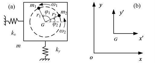
Using Lagrange equation, and letting the x, y, φ1 and φ2 as the generalized coordinates, we obtain motion equations of the vibration system described by the forms [8-11]:
M¨y+fy˙y+kyy=m1r1(˙φ21sinφ1-¨φ1cosφ1)+m2r2(˙φ22sinφ2-¨φ2cosφ2),
J1¨φ1+f1˙φ1=Te1-m1r1[¨ycosφ1-¨xsinφ1],
J2¨φ2+f2˙φ2=Te2-m2r2[¨ycosφ2-¨xsinφ2].
where M=m+m1+m2 is the vibration mass; Ji≈mir2i is the moment of inertia; fi is the damping coefficients; Te1 and Te2 are the electromagnetic torques of two motors; (˙⦁) and (¨⦁) denote d⦁/dt and d2⦁/dt2, respectively; Above mentioned, i=1, 2.
3. Synchronization condition and stability condition of synchronization state
We assume the average phase between two REMs and their phase difference are φ and 2α, respectively [8-11], then we obtain, φ1=φ+α, φ2=φ-α. Since the periodical vibration of the vibration system, the changes of mechanical angular velocities of two motors are periodic as well. The average value of their average velocities over the least common multiple period between two REMs must be constant, ω0=constant. Assuming the instantaneous change coefficients of ˙φand ˙α to be ε1 and ε2, we obtain ˙φ1=(1+ε1+ε2)ω0, ˙φ2=(1+ε1-ε2)ω0.
According to the previous works [8-11], and selecting m1=m2=m0, r1=r2=r, the responses of Eq. (1) can be approximately expressed in the forms:
y=-rmrμy[sin(φ+α+γy)+sin(φ-α+γy)],
where:
nβ=ω0ωnβ,γβ=arctan2ξβnβn2β-1,
and π-γβ is the phase angle, (β=x,y).
Differentiating x and y in Eq. (2) with respect to time t, we obtain ¨x, and ¨y. Substituting them into the last two equations in Eq. (1), and integrating them over φ=0~2π, and neglecting the high-order terms of ε1 and ε2, the motion equations of two REMs are expressed in the forms:
J2(˙ˉε1-˙ˉε2)ω0+f2(1+ˉε1-ˉε2)ω0=Te1-(χ'21˙ˉε1+χ'22˙ˉε2+χ'21ˉε1+χ'22ˉε2+χf2+χa),
where:
χ'21=Tu(Wc+Wccos2ˉα+Wssin2ˉα)ω0,χ'22=Tu(-Wc+Wccos2ˉα+Wssin2ˉα)ω0,
χ11=2Tu(Ws+Wscos2ˉα+Wcsin2ˉα),χ12=2Tu(Ws-Wscos2ˉα-Wcsin2ˉα),
χ21=2Tu(Ws+Wscos2ˉα-Wcsin2ˉα),χ22=2Tu(-Ws+Wscos2ˉα-Wcsin2ˉα),
χf1=χf2=TuWs(1+cos2ˉα),χa=TuWcsin2ˉα,Tu=m0r2ω202,
Ws=rm(μxsinγx+μysinγy),Wc=-rm(μxcosγx+μycosγy).
Compared with the change of φ(˙φ=ω0) with respect to time t, those of α, ε1, ε2, ˙ε1 and ˙ε2 are very small. Therefore, they are considered to be slow-changing parameters, while the change of φ is considered as fast-changing parameter [8-11]. During the aforementioned integration over φ=0~2π, α, ε1, ε2, ˙ε1 and ˙ε2 can be assumed to be the middle valves of their integrations ˉα, ˉε1, ˉε2, ˙ˉε1 and ˙ˉε2, respectively.
If the variation coefficient of mechanical angular velocity of the REM is ε during the steady state operation of the vibration system, i.e., ω=(1+ε)ω0. Applying the first-order Taylor expression around ω0, the electromagnetic torque of the DC motor in the steady state can be obtained as follow [24]:
where:
and U is voltage, R is armature resistance, Φ is exciting flux, Ke is electromotive force constant, Km is torque constant, ω is rotational speed of the motor.
The electromagnetic torques of two motors in Eq. (4) can be expressed as follows:
We assume the parameters of two motors are the same, ke01=ke02=ke0, f1=f2=f0. Substituting Eq. (5) into Eq. (3), and writing Eq. (3) in matrix form that adding two formulas in equations to obtain the first row, and subtracting second formula from the first one to get the second row, then we obtain:
where:
μ=2+Wc,κ=(ke0+f0ω0)Tu+2Ws,
a11=μ+Wccos2ˉα,a12=Wssin2ˉα,a21=-Wssin2ˉα,a22=μ-Wccos2ˉα,
b11=κ+2Wscos2ˉα,b12=-2Wcsin2ˉα,b21=2Wcsin2ˉα,b22=κ-2Wscos2ˉα,
u1=ω0[(Te01+Te02)-2f0ω0-2TuWs(1+cos2ˉα)]2Tu,
u2=ω0[(Te01-Te02)-2WcTusin2ˉα]2Tu.
In Eq. (6), ˉε1 and ˉε2 represent the perturbation parameters that the average angular velocities of two motors and the phase difference between two REMs. Eq. (6) describes the coupling relation of two REMs and is referred to as the dimensionless coupling equation of those.
3.1. Synchronization condition
If the vibration system can implement synchronization motion of two REMs, the average values ε1 and ε2 during the interval of the single period T=2π/ω0 must be zero, i.e., ˉε1=0 and ˉε2=0. Then, we can obtain u1=0 and u2=0 from Eq. (6) as follows:
where the term Te01+Te02 is the sum of the electromagnetic torques of two motors; the term 2f0ω0 is the sum of the damping torques of two REMs. TL=2TuWs(1+cos2ˉα) is the sum of the load torques that the vibration system acts on two motors. So Eq. (7) is the torque balance equation that the vibration system operates in the steady state.
According to Eq. (8), the electromagnetic torque difference between two motors is defined as TD=Te01-Te02, the torque of frequency capture is defined as TC=2WcTu. Rearranging Eq. (8) as follow:
Since |sin2ˉα|≤1, the synchronization condition is that the torque of frequency capture must be greater than or equal to the absolute value of the electromagnetic torque difference between two motors, TC≥|TD|.
From Eq. (3), when the vibration system operates in steady synchronization state, the load torques that the vibration system acts on the two motors can be expressed as follows:
The adjusting torque is defined as Wcsin2ˉα. Assuming the phase of motor 1 leads that of motor 2, the adjusting torque acts on the motor of leading phase as load torque to decrease its angular velocity, and acts that of lagging phase as driving torque to increase its angular velocity, which ensure two REMs operate in synchronization state. If the voltages of two motors are different, their electromagnetic torques are also different. The load torques of two motor are different because the adjusting torque, which ensure there is a phase difference between two REMs. Applying this principle, this phase difference can change the response amplitude with satisfying the synchronization condition, which will be explained in the following chapter.
Under the condition of satisfying the synchronization condition, we define absolute ratio between the torque of frequency capture TC and the sum of the load torques TL as synchronization ability coefficient ζ, which represents the ability that the vibration system adjusts the load torque of each motor to implement synchronization motion of two REMs. The greater value of synchronization ability coefficient, the easier implementing synchronization motion:
where ζ is the nonlinear function of nβ. We will explain its nonlinear characteristic in the next section.
3.2. Stability condition of synchronization state
The kinetic energy T and potential energy V of the vibration system:
In one vibration periodic, Hamilton’s average action I can be expressed as:
According to Eq. (9), the solution of 2ˉα has two values, which correspond two different states, and using 2α* to represent the steady solution. Based on the principle of Hamilton, when the second-order derivative of Hamilton’s average action Iwith respect to α is greater than zero, the dynamic system is stable. Substituting Eq. (2), Eq. (12) and Eq. (13) into Eq. (14) and rearranging them, we can obtain the stability condition of synchronization state as follow:
where W≈Turmn2β/1-n2β, W is defined as the stability coefficient of synchronization state.
From the Eq. (15), we can know that only the product of stability ability coefficient and cosine function of the phase difference is greater than zero to ensure the stability of synchronization state. Namely when W>0, the stable domain of 2α* is (-π/2,π/2), and when W<0, the stable domain of 2α* is (π/2,3π/2).
4. Numeric discussions
The previous chapter has given some theoretical analyses in the simplified form on synchronization issue. This section will analyze quantitatively the numerical results of dynamical characteristics of the vibration system to verify the validity of the previous theoretical results. The parameters of the vibration system in this paper are: M=744 g, m= 23 g, r= 10 mm, kx=ky= 4930 N/m, fx=fy= 30N∙s/m, f0= 0.0001, KmΦ= 0.0043 Nm/A, KeΦ= 0.0409 Vs/rad, R= 5.5 Ω.
According to Eq. (2), when two REMs operate in synchronization state, we can deduce the max amplitude of response λβ in simply form with using the method of mathematical extreme solution as follow:
where:
According to Eq. (16), we can obtain the relation between the phase difference and the max amplitude of response as shown in Fig. 2. The dimensionless parameter Aα is decreasing with increasing the phase difference. This is show that the response amplitude of the vibration system changes with changing the phase difference, which can achieve the decoupling between the response amplitude and exciting frequency.
Fig. 2Comparison of Aα with 2α
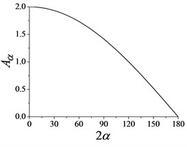
Fig. 3Synchronization ability coefficient
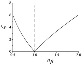
Fig. 4Stability coefficient of synchronization state
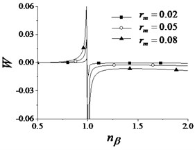
Fig. 3 shows synchronization ability coefficient changes with changing frequency ratio nβ. It should be noteworthy that, the vertical line ζ=1, which splits the domain in Fig. 3 into two parts. One is sub-resonant domain (ω0<ωnβ) on the left hand side, and another is super-resonant domain (ω0>ωnβ) on the other side. As shown in Fig. 3, we can see that the closer resonance point, the smaller synchronization ability coefficient.
Fig. 4 shows the stable ability coefficient of synchronization state with different mass ratio. Its tendency is similar to Fig. 3 that there is a break point at nβ=1. When the vibration system operates in sub-resonant state, W>0 and the stable domain of 2α* is (-π/2,π/2), and when it operates in super-resonant state, W<0 and the stable domain of 2α* is (π/2,3π/2).
5. Numerical simulation
In this section, there are two simulation results are carried out, one case is two REMs operate in sub-resonant domain and another is two REMs operate in super-resonant domain. For the convenience of observing the initial state, we put the record time of data delay two seconds in post-processing, and below no longer explain it.
Fig. 5 shows the case that two REMs operate in a sub-resonant domain. During the starting process in Fig. 5(a), the angular velocities of two motors are equal to each other because their physical parameters are same. When time at about 10 s, the phase of motor 2 adds a disturbance of π/6 in Fig. 5(b), after that, the state of the vibration system gradually returns to the previous one, which indicate that the stability of synchronization motion is very strong. In this stage, the synchronization angular velocity nears to 758 r/min, the phase difference is equal to zero. Later, the voltage of motor 2 is subtracted 0.1 V, 0.1 V, 0.15 V, 0.05 V, after those two REMs are de-synchronization. Before de-synchronization of two REMs, the phase difference reaches 70.3°, which satisfies synchronization condition. From the above process of changing voltage of motor 1, it is seen that the phase difference increases gradually, and the amplitude of response in vertical direction decreases gradually in Fig. 5(c), which accord with Fig. 2.
Fig. 5Dynamic characteristic of the vibration system with the sub-resonant state: a) angular velocities, b) the phase difference, c) the response amplitude in y-direction

Fig. 6Dynamic characteristic of the vibration system with the super-resonant state: a) angular velocities, b) the phase difference, c) the response amplitude in y-direction

In Fig. 6, two REMs operate in a super-resonant domain. The same as Fig. 5, at about 10 s, a disturbance of π/6 is also added to the phase of motor 1, after about 5 s, the state of the vibration system gradually return to the previous one. In this stage, the synchronization angular velocity nears to 1654 r/min in Fig. 6(a), the phase difference is equal to 180° in Fig. 6(b). Later, the voltage of motor 1 is added 0.2 V every 10 s until de-synchronization of two REMs. Comparing the results in Fig. 5, two REMs stably operate in the super-resonant with opposite phase. As shown in Fig. 6(c), the response amplitude of y-direction is very small because the phase difference leads to decrease the sum exciting forces of two REMs.
From these analyses, these dynamic characteristic accord with the theoretical results in previous sections. We can know that the work point of the vibration system has better select at sub-near-resonant to acquire big enough amplitude.
6. Experiments
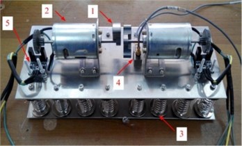
Fig. 7 shows the mechanical composition of the dual-rotors exciter, which consists of two DC vibration motors, the vibration rigid, the springs and the support base. No. 1 represents REMs, No. 2 represents DC motors, No. 3 represents the suspension system, No. 4 represents the acceleration sensors, and No. 5 represents photoelectric rotation velocity sensors. The signals of the vibrations in the horizontal and vertical directions, and the rotation velocities of two REMs are collected by 3650D measurement frontends of B&K. While the powers of the two motors are supplied by GPD-3303S of Good Will Instrument.
Fig. 7The dual-rotors exciter
The experiment schemes according to simulation ones are achieved in Fig. 5 and Fig. 6.
Fig. 8 shows the case that two REMs operate in a sub-resonant state. When time at about 10 s, the power of motor 2 is cut during 1 s, the angular velocity of motor 2 quickly descend, the phase difference exhibits non-periodicity behavior, and the response amplitude of y-direction also changes.
In Fig. 9, two REMs operate in a super-resonant domain. Since the physical parameters of two motors and the structure symmetry of the vibration system, etc., the response amplitude is not equal to zero when the phase difference closes to 180°.
The results of matching between numerical simulations and experimental results show they are very good consistency. Through the comparison between numerical simulations and experimental results, the validity of theoretical analyses is proved, which helps the design of the dual-rotors exciter.
Fig. 8Experiment results of the vibration system with the sub-resonant state: a) angular velocities, b) the phase difference, c) the response amplitude in y-direction

Fig. 9Experiment results of the vibration system with the super-resonant state: a) angular velocities, b) the phase difference, c) the response amplitude in y-direction

7. Conclusions
From the theoretical analyses, numerical simulations and experimental results in the present paper, the following remarks should be stressed:
This paper proposes an analytical approach to investigate synchronization and coupling dynamic characteristic of a dual-rotors exciter. By introducing the average method of small parameters, the dimensionless coupling equation of the vibration system is deduced, which describes the coupling dynamic characteristics of the REMs.
The synchronization condition of two REMs operated in synchronous state is derived, which is that the torque of frequency capture is equal to greater than the absolute value of the difference between the residual torques of two motors. With the adjustment of the phase difference between two REMs to change response amplitude, the decoupling between response amplitude and exciting frequency can be realized under the synchronization condition.
According to the principle of Hamilton, the stability condition of the vibration system implementing synchronization is acquired. The coupling dynamic characteristic that the vibration system has selecting motion is discussed. For a dual-rotors exciter system with small damping, the phase difference between two REMs is stabilized at (-π/2,π/2) with a sub-resonant state, while it is stabilized at (π/2,3π/2) with a super-resonant state.
By the comparison of numerical simulations and experimental results, the feasibility of theory method is proved. The synchronization condition and stability condition of synchronous state can help to the design of a dual-rotors exciter.
References
-
Wen B. C., Fan J., Zhao C. Y., et al. Vibration Synchronization and Controlled Synchronization in Engineering. Science Press, Beijing, 2009.
-
Huygens C. Horologium Oscilatorium. Paris, France, 1673.
-
Blekhman I. I. Self-synchronization of vibrators in some types of vibrational machines. Inzhenerny Sbornik, Vol. 16, 1953, p. 49-72, (in Russian).
-
Blekhman I. I. Synchronization in Science and Technology. ASME Press, New York, 1988.
-
Blekhman I. I., Fradkov A. L., Nijmeijier H., et al. On self-synchronization and controlled synchronization. System and Control Letters, Vol. 31, 1997, p. 299-305.
-
Blekhman I. I., Fradkov A. L., Tomchina O. P., et al. Self-synchronization and controlled synchronization: general definition and example design. Mathematics and Computers in Simulation, Vol. 58, 2002, p. 367-384.
-
Blekhman I. I., Sorokin V. S. On the separation of fast and slow motions in mechanical systems with high-frequency modulation of the dissipation coefficient. Journal of Sound and Vibration, Vol. 329, 2010, p. 4936-4949.
-
Zhao C. Y., Zhu H. T., Wang R. Z., et al. Synchronization of two non-identical coupled exciters in a non-resonant vibration system of linear motion, Part I: Theoretical analysis. Shock and Vibration, Vol. 16, Issue 5, 2009, p. 505-516.
-
Zhao C. Y., Zhao Q. H., Zhang Y. M., et al. Synchronization of two non-identical coupled exciters in a non-resonant vibration system of plane motion. Journal of Mechanical Science Technology, Vol. 25, Issue 1, 2011, p. 49-60.
-
Zhang X. L., Zhao C. Y., Wen B. C. Theoretical and experimental study on synchronization of the two homodromy exciters in a non-resonant vibrating system. Shock and Vibration, Vol. 20, 2013, p. 327-340.
-
Zhang X. L., Wen B. C., Zhao C. Y. Vibratory synchronization transmission of two exciters in a super-resonant vibrating system. Journal of Mechanical Science and Technology, Vol. 28, Issue 6, 2014, p. 2049-2058.
-
Balthazar J. M., Palacios J. L., Reyolando M. B. Some comments on the numerical simulation of self-synchronization of four non-ideal exciters. Applied Mathematics and Computation, Vol. 164, 2005, p. 615-625.
-
Balthazar J. M., Palacios J. L., Reyolando M. B. Short comments on self-synchronization of two non-ideal sources supported by a flexible portal frame structure. Journal of Vibration and Control, Vol. 10, 2004, p. 1739-1748.
-
Quinn D., Rand R., Bridge J. The dynamics of resonance capture. Nonlinear Dynamics, Vol. 8, 1995, p. 1-20.
-
Nijmeijer H. A dynamical control view on synchronization. Physica D: Nonlinear Phenomena, Vol. 154, Issue 3, 2001, p. 219-228.
-
Yamapi R., Woafo P. Dynamics and synchronization of coupled self-sustained electromechanical devices. Journal of Sound and Vibration, Vol. 285, 2005, p. 1151-1170.
-
Yamapi R., Filatrella G. Strange attractors and synchronization dynamics of coupled Van der Pol-Duffing oscillators. Communications in Nonlinear Science and Numerical Simulation, Vol. 13, 2008, p. 1121-1130.
-
Perlikowski P., Stefański A., Kapitaniak T. 1:1 Mode locking and generalized synchronization in mechanical oscillators. Journal of Sound and Vibration, Vol. 318, 2008, p. 329-340.
-
Acebrón J. A., Bonilla L. L., Perez V. C. J., et al. The Kuramoto Simple paradigm for synchronization phenomena. Reviews of Modern Physics, Vol. 77, 2005, p. 137-185.
-
Acebrón J. A., Bonilla L. L., Perez V. C. J., Ritort F., et al. The Kuramoto model: a simple paradigm for synchronization phenomena. Reviews of Modern Physics, Vol. 77, 2005, p. 137-185.
-
Tanaka H. A., Lichtenberg A. J., Oishi S. Self-synchronization of coupled oscillators with hysteretic responses. Physica D: Nonlinear Phenomena, Vol. 100, 1997, p. 279-300.
-
Miklos A., Szabo Z. Mechanical synchronization in dual-rotor vibroactuator. Applied Mathematics and Mechanics, Vol. 13, 2013, p. 41-42.
-
Miklos A., Szabo Z. Simulation and experimental validation of the dynamical model of a dual-rotor vibrotactor. Journal of Sound and Vibration, Vol. 334, 2015, p. 98-107.
-
Ruan Y., Chen B. S. Control Systems of Electric Derives-Motion Control Systems. China Machine Press, Beijing, 2010, (in Chinese).
About this article
This study was supported by National Natural Science Foundation of China 51375080.

