Abstract
The MBC (calibration model-based) toolbox in MATLAB software and Ricardo Wave were used to optimize the power performance of a gasoline engine. In the calibration process, Firstly, the wave simulation model of the engine was established and validated; then, engine operating points were determined by using the design of experiments (DOE) method, and parameters and performance (torque, fuel consumption, power and the cylinder maximum pressure, etc.) of the engine at these operating points were calculated by the simulation model. Finally, the engine mathematical statistical model was established and calibration optimization. The engine ignition advance angle, air-fuel ratio and the torque of the engine were obtained. The results show that the method combined with the modern DoE test design theory and automatic calibration technology not only makes the engine torque from 198 Nm to 215 Nm, but also greatly reduces the test time and improve the calibration efficiency
1. Introduction
With the market for automobile power, economy, comfortable and safety performance requirements continue to increase, and state of the automotive emissions increasingly strict control, how to calibrate the engine electronic control parameters is particularly critical. To this end, the number of electronic control parameters of the engine is increasing year by year. Automotive electronic control engine parameters have to be calibrated by the 2 in 1988 to the 7 to 10 in 2016 and calibration work for engineers have been increased from 8 map in 1980 to over 1000 map in 2016. With the increasing complexity of the gasoline engine, it is expected that the parameters of next generation engine will rise to 10000 to 15000. In recent years, many scholars and experts have done a lot of research on the control strategy and calibration method of the engine electronic control system. However, most of the research process is that the engine electronic control hardware system is identified, then the engine bench test and calibration optimization. According to the process, the engine calibration workload is quite large and the cost is high.
A calibration technique based on engine model is introduced in this paper. It is a kind of optimization method which combines the mathematical optimization theory and the engine calibration technology. It uses the MBC toolbox in the MATLAB software on engine the calibration and optimization, mainly including experiment design to obtain effective working point, establishment and validation of the engine simulation model, the establishment of engine statistical model and calibration of the control parameters. Different experimental design methods and statistical models have a great influence on the quality of final calibration. This paper adopts Design of Experiment (DoE) test design method.
2. The method of model-based calibration
2.1. Model-based calibration
This is an offline optimization technique based on the Design of Experiments (DoE) and statistical tools to construct the response between decision variables (such as ignition advance ignition, air-fuel ratio) and the optimization objectives (such as maximizing torque and power, minimizing emissions and fuel economy or trade-off between these objectives) of an engine. The DoE includes the design planning of the engine test points and region, modeling methodology and optimization strategy. The planning of engine test points and its corresponding decision variable solutions can be accomplished using different statistical tools such as Latin Hypercube Sampling, Centre Composite Design, V-optimal design, and D-optimal design. The response surface can be constructed using different approximation modeling techniques such as polynomials, radial basis function, ANNs, etc. or a hybrid of these above-mentioned models. The typical engine calibration procedures using model-based calibration methodology are described below:
1) Determine the engine-operating region and points based on the engine speed and load.
2) Determine the control parameters of the studied engine, based on DoE.
3) Measure engine performances output data using control parameters.
4) Use different approximation modeling techniques to build the response surface.
5) Optimize response surfaces offline with different desired objectives by altering the control parameters.
6) Validate the optimal control parameters and desired objectives with real engine testing and then go back to step 1, if it is required.
2.2. Optimization objectives and constraints
The maximum torque of the engine is not the same as the maximum torque of the engine under the condition of constant intake and rotating speed for different ignition advance angle and air-fuel ratio. Therefore, when calibrating the ignition advance angle and the air-fuel ratio, the optimization of the dynamic performance is a single objective optimization problem. In this article, the calibration target model is defined as:
Tex≤limTex,
Ppeak≤limPpeak,
where Ttq is engine torque, S is ignition advance angle, N is engine speed, L is throttle position, A is air-fuel ratio, Tex is exhaust temperature, Ppeak is the maximum cylinder pressure.
In this paper, the optimization objective is to optimize the engine torque, and the optimization variables are ignition advance angle and air-fuel ratio. That is to say, by calibrating the ignition advance angle and the air fuel ratio, the engine is to meet the limit conditions of the exhaust temperature and the maximum pressure in the cylinder, and the maximum torque can reach the optimum.
3. Development of model based calibration
3.1. Process of experimental design
With the increase of ECU control parameters, the intrinsic relationship and interaction between parameters are more closely. Therefore, it is difficult to use the traditional calibration method of multi variable cross combination to carry out the engine test. At present, design of experiment (DoE) has been widely used in the engine calibration process. It its basic idea is to make the engine system equivalent to a mathematical model. Under different conditions, the control variables of the engine, such as the ignition advance angle, is the input variable of the mathematical model, the torque of the engine is the response variable of the mathematical model. The MBC Toolbox provides 3 design methods, namely the classical design method, the space filling method, and the optimal design method. Space filling method is a kind of experimental design method based on probability distribution. The principle can be shown that assign a predetermined set of experimental points according to different rules which based on the principle of maximizing the minimum distance and minimizing maximum distance in a test space with multiple input parameters, so that the experimental points can be filled in the whole experimental space. When facing a new engine, the principle of engine unfamiliar and has less experience of the calibration object, calibration workers is more suitable for this method. In this paper, the space filling method is used for the experimental design.
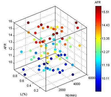
First, the ignition advance angle is regarded as the local variable, the speed, the throttle position and the air-fuel ratio are global variables, then, the external characteristics of the engine are used as the limit. The 80 test points are finally determined after the experimental design, as shown in Fig. 1.
Fig. 1Test points after experiment design
3.2. Engine simulation model
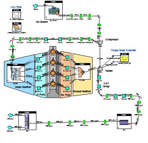
Ricardo Wave is a abundant function engine simulation software with rich combustion model, it has a powerful auxiliary modeling tool and wealth of control functions. A four cylinder, four stroke engine model is built with Wave Ricardo, as shown in Fig. 2.
Table 1Main parameters of gasoline engine
Type | Inline 4-cylinder,4-stroke |
Intake | Turbocharger |
Displacement | 2.0 L |
Bore | 82.5 mm |
Stroke | 92.8 mm |
Compression ratio | 9.6 |
Rated power | 76 kW/4000 r/min |
Maximum torque | 280 Nm/2500-3500 r/min |
Table 2Part of the test data of gasoline engine
Load | AFR | Speed | Spark | BTQ |
% | Ratio | r / min | CA | Nm |
0.825 | 13.02 | 2588 | 5 | 172.1 |
0.825 | 13.02 | 2588 | 9 | 175.1 |
0.825 | 13.02 | 2588 | 13 | 173.8 |
0.825 | 13.02 | 2588 | 17 | 168.7 |
0.825 | 13.02 | 2588 | 21 | 160.5 |
0.825 | 13.02 | 2588 | 25 | 170 |
0.825 | 13.02 | 2588 | 29 | 157.8 |
0.825 | 13.02 | 2588 | 33 | 124.5 |
0.825 | 13.02 | 2588 | 37 | 113.6 |
0.825 | 13.02 | 2588 | 41 | 106.4 |
Table 1 shows the main parameters of the engine. The model is a cylinder direct injection engine with Turbo-charging system and use woschni heat transfer model and Webb function analysis cylinder heat release rate, which can be depicted as follows:
where xα is the percentage of burned fuel, a is crank angle, aβ is combustion start angle, az is duration angle of combustion, m is combustion index.
Experimental design operating point one by one sequentially scans the ignition advance angle regard as local variables nodes. Each operating point scanning 10 times, a total of scan is 80∙10 =800 times. Then, the Wave model is used to calculate the torque, the power, exhaust temperature and the maximum cylinder pressure at the 800 points. Table 2 shows the part of the data obtained.
Fig. 2Wave model of 4 stroke gasoline engine
3.3. Build engine statistical model
The input parameters of the engine interact with each other and the relationship of a variety of input parameters and performance index are very complex. Therefore, a two-stage statistical model of gasoline engine is built under the condition of the ignition advance angle as a local variable, speed, throttle position and air-fuel ratio as global variables, torque as response variables, as shown in Fig. 3. In order to make statistical model is closer to the actual engine, you need to add some constraints, such as the maximum cylinder pressure Ppeak is less than or equal to 8 MPa (Ppeak≤8 MPa), to limit the engine cylinder pressure is too high. The two-stage statistical model can reflect the mapping relationship between local variables and global variables. In the local model, piecewise quadratic polynomial regression model of the ignition advance angle is established, which can be depicted as follow:
where c1, c2, k, max are regression coefficients, k is local optimum ignition advance angle, max is local maximum torque, c1 is second-order coefficient of the quadric polynomial regression model on the right of the local maximum torque point. c2 is second-order coefficient of the quadric polynomial regression model on the left of the local maximum torque point. And the regression coefficient is a function of the global variables (N, L, A) in the statistical model, which using radial basis function (Hybrid RBF) to describe. The expression of Hybrid RBF is depicted as follow:
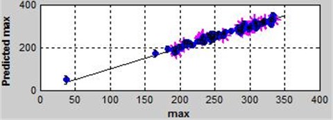
where Uk is output value of the transfer function, x is input sample, c is the center value, σ is a deviation, y is the network predicted output values, N is the number of hidden layer nodes, W is the connection weights, and θ is a threshold, the subscript k is the kth unit.After building the model, it is needed to check the local model’s data and determine whether the global model is reasonable by the root mean square error. If the root mean square error is larger, a point in a data set or entire data set can be removed without affecting the entire curve fitting trend. The accurate fitting results can be obtained by checking and removing the data back and forth, such as the regression coefficient (max). Fig. 4 is the distribution map of the max predictive value and the observed value. You can see clearly that most of the points are close to a straight line, and the model error is less than 3 %.
Fig. 3Two-stage statistical model
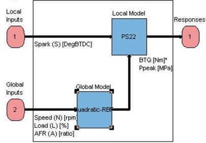
Fig. 4Prediction and observation of max in the function of Hybrid RBF
4. Calibration results and discussion
4.1. Optimization
In this paper, the optimization goal is the maximum torque of the engine while the constraint is the exhaust temperature and the maximum pressure in the cylinder and variables is the ignition advance angle and the air fuel ratio. Three algorithms (foptcon, NBI and Worked example) is provided by CAGE of MATLAB toolbox using the single objective function. The foptcon algorithm is suitable for the model with arbitrary number of free variables, single target and constrained model, so the foptcon is used. The above statistical model is imported into CAGE to optimize. Fig. 5 is the optimization model.
Fig. 5The optimization model of torque
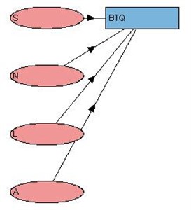
Fig. 6The map of air-fuel
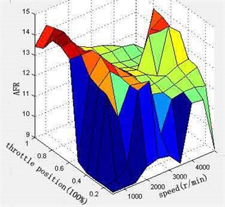
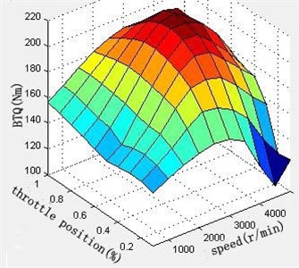
Set the ignition advance angle (S) and the air-fuel ratio (A) as Free Variable (can be optimized value), the rotational speed (N) and the throttle position (L) as Fixed Variable (horizontal and vertical value of map). The calibration table is set up while the interval of the rotational speed is 500r/min and the throttle position is 0.1. In this paper, the ignition advance angle and the air-fuel ratio are optimized, and their MAP and torque are obtained. As shown in Figs. 6-8. It can be seen from the figure that the curves of ignition advance angle and air -fuel ratio is relatively smooth. Under full load, when speed is 1000 r/min-2500 r/min, the engine torque increases with the increase of the speed; speed is 2500 r/min-5000 r/min, torque decreases with the increase of rotational speed, and the maximum torque is 215 N∙m.
Fig. 7The map of spark angle
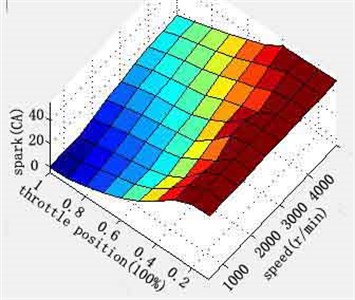
Fig. 8The map of torque
4.2. Discussion
The size of ignition advance angle directly affects the whole combustion process in the cylinder, and then directly affects the power performance, economy and emission performance of the engine. The principle of ignition advance angle calibration is that engine running smoothly is the most important, followed by the economy in idle condition. At the low and medium speed condition, the ignition advance angle calibration must first ensure enough low speed torque and performance of dynamic response. In the medium and high speed conditions, target of the engine ignition advance angle calibration is maximum output power under the condition of no knock and misfire. Namely, the engine's economic performance is excellent. In general, the ignition advance angle is increased with the increase of the rotating speed, and decreases with the increase of the load.
The air-fuel ratio has a great influence on the combustion of the engine cylinder, which directly affects the power, economy, emission and reliability of the engine. Calibration principle is in low speed conditions, under the premise of ensuring the calibration target, in order to meet the engine’s low speed dynamic response, concentration of the mixed gas should be increased; in high speed condition, the calibration of air-fuel ratio mainly considers economic performance. Under low load condition, the mixed gas is concentrated, but the degree of concentration should be decreased with the increase of the load. Most of the time of the engine is in the medium load condition. At the condition, the throttle valve position is enough, and the effect of exhaust gas dilution already no longer exists. Therefore, in order to obtain the best fuel economy, dilute mixture gas is supplied. At high load, the throttle opening has more than three-quarters. At this stage, in order to meet the requirements of the engine power, with the increase of the opening of the throttle valve air-fuel ratio decreased.
There will be some sites that engine cannot physically achieve such as high speed (8000 rpm) at low load (10 % throttle position). The statistical model has considered the boundary operating region for normal operating conditions to be calibrated and did not concentrated on the unrealistic engine operating conditions. Future calibration could need to set or modify manually for neatness.
5. Conclusion
1) A method for calibration of control parameters based on engine model is established. Combining the simulation software Ricardo Wave and toolbox MBC of MATLAB to calibrate and optimize engine, including determination of the experimental design, generation of the engine test points, establishment of wave simulation model, establishment of engine statistical model and optimization. At last, the map of ignition advance angle, fuel-air ratio and engine torque is generated.
2) The method of DoE test design can not only optimize the engine, improve the power of the engine, but greatly reduces the calibration cost, Shortens the calibration time. The maximum torque is 215 Nm while 198 Nm before optimized.
References
-
Fontana G., Galloni E. Variable valve timing for fuel economy improvement in a small spark-ignition engine. Applied Energy, Vol. 86, Issue 1, 2009, p. 96-105.
-
Kianifar M. R., Campean L. F., Richardson D. Sequential DoE framework for steady state model based calibration. SAE International Journal of Engines, Vol. 6, Issue 2, 2013, p. 843-855.
-
Li Yunqing, Wang Haiying, Cheng Chuansong, Wang Yan-Hua Simulation and investigation of model-based calibration of gasoline engine in boost and Matlab Environment. Internal Combustion Engine Engineering, Vol. 31, Issue 4, 2010, p. 78-82.
-
Ni Ji-min, Yang Ting-ran, Yang Jian Internal Combustion Engine Engineering. Optimizing Electrical Control Parameters of Common Rail Diesel Engine by Model-based Method, Vol. 29, Issue 1, 2008, p. 6-10.
-
Ho T., Karri V. Optimizing the sum performances of ignition timing and air to fuel ratio on torque of hydrogen powered car. The 15th Asia Pacific Automotive Engineering Conference, Hanoi, Vietnam, 2009.
-
Kaji H. Automotive Engine Calibration with Experiment Based Evolutionary Multi-Objective Optimization. Kyoto University, Graduate School of Informatics, Kyoto, 2008.
-
Watanabe K., Tumer M. An automotive engine calibration system using microcomputer. IEEE Transactions on Vehicular Technology, Vol. 33, Issue 2, 1984, p. 45-50.
