Abstract
To address the ricochet problem in penetration process, the mathematical model of projectile penetrating into concrete target is established according to the basic kinetic equation and surface layer mechanism. The motion trajectory of projectile nose is obtained. Experimental studies on projectiles with different nose penetrating into concrete targets are conducted to explain the ricochet problem. These studies analyze fifty-four penetration conditions under different initial velocities and oblique angles when the projectiles have flat, hemispherical, ogive noses and conical noses. The regularity and critical angles of ricochet are analyzed with different nose shapes at different velocities. Results show that the ricochet angle increases depending on nose sharp and penetration velocity. The factors affecting the ricochet from big to small were analyzed via orthogonal test. The results show that with increasing the velocity from 652 m/s to 1022 m/s, the critical angle increases from 44° to 66°. The order of factors affecting the ricochet from big to small is the shape of the nose, the material of the projectiles and the penetrating velocity respectively.
1. Introduction
Research on impact resistance of concrete materials began in the 1940s and developed rapidly in the military field. This research emphasized the nuclear power plant protection shell, underground military bases, and other projects to consider the impact of the demand for the accident. Many new problems need to be solved given the development of new high-speed kinetic energy weapons and anti-impact tests of concrete. Concrete materials are complex and multi-phased. The penetration of projectile into concrete is a transient and complex process that is related to the mechanical properties of concrete materials (i.e., plastic flow, hardening softening, damage, fracture). The force of a projectile is not symmetrical given the initial angle of the attack, the actual angle of attack, the velocity, the shape of the warhead, and the material. Research of ricochet mainly concentrated on improving projectile penetrating attack ability to improving the penetration effect [1] and the corresponding capability of the military in anti-missile protection via ricochet. Goldsmith [2] summarized the theory, numerical simulation, and experimental studies on non-ideal impact of projectile penetration into a steel target. Chen [3] proposed an analysis model of a rigid projectile that penetrates a metal target to predict the critical conditions of the ricochet. Li [4] found that the ricochet angle of a flat-nosed projectile is smaller than that of a spire-shaped projectile; the ricochet of a slip ring pointed projectile ricocheted off a critical angle is greater. Segletes [5] analyzed the ricochet of a long rod projectile. Yu [6] and Wu [7] studied ricochet with the effect of initial conditions on the target. Guo [8] proposed a semi-cutting ring projectile to improve anti-penetration performance and subsequent ricochet. Hu [9] attained ricochet rule and the critical angle range of ricochet by simulation bullets with different head shapes penetrating a steel target.
This paper established the mathematical model and carried out experiments to study ricochet rules in consideration of the nose shape and velocity of the projectiles penetrating into concrete. It analyzed the ricochet critical angle of projectiles with different nose shapes on the basis of simulation results. The influence factors of ricochet are obtained through orthogonal analysis, which provides the basis for the study of large-angle oblique penetration into a target subjected to projectile.
2. Mathematical model of ricochet
2.1. Spalling mechanism
The stress wave is inclined to free surface of concrete in penetration process. The incident wave is reflected to expansion wave and shear wave in the free surface. The intensity distribution of these reflective waves is related to oblique angle.
Compression waves are obliquely incident to the free surface of concrete. The incident compression waves arrive and reflect as reflection waves. While the incident compression waves follow the front arriving wave and reflect as the reflection waves. The incidence and reflection waves are conducting on the position of the free surface. Fig. 1 is the process of wave incident and reflection at a free surface at a certain time. MN is a free surface.
Fig. 1Reflection of plane wave
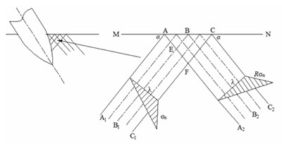
Fig. 2Superposition of waves
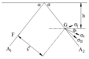
Referring to Ning [10], the wavelength of incident wave is λ, the intensity of wave is σn, the incident angle is α. According to the relationship between reflection waves and incident waves, the wavelength of reflection wave is λ, the reflection angle is α, the intensity is Rσn. The reflection coefficient R, which is associated with the incident angle and the material Poisson’s ratio υ, is defined as:
The stress state is the superposition of the incident wave and the reflected wave intensity at the specific point of view in the area of the incident wave and the reflected wave. In Fig. 1, the stress is superposition by the intensity of the reflected wave and the intensity of the incident wave at the 1/2 wavelength at E point. The stress is reflected by the intensity of reflected plane wave at F point. Point G is in the line intersect of the reflected wave and the incident plane wave (Fig. 2). The distance of G point from the incident plane wave surface is ξ. The intensity of incident plane wave is σI=(1-ξ/λ)σn at G-spot, the direction along the incident plane wave front surface normal direction. The intensity of reflection plane wave is σII=Rσn at G-spot, the direction along the reflection plane wave front in the direction normal. The angle between two plane waves is 180°. With wave superposition principal stress formula, the superposition principal stress is [10]:
The direction of the main stress is added, the angle line of two stresses is parallel to the free surface. The angle of the main stress and the parallel line, which is also the angle between the main stress and the free surface, is defined as:
Then Eq. (3) is simplified to:
According to Eq. (4), the main stress is tensile stress, and the maximum tensile stress is greater than the tensile strength of concrete, then there will be a layer of crack in the concrete, and the direction of the crack is perpendicular to the direction of maximum tensile stress. The distance from the free surface to the layer is:
2.2. The governing equation of motion
The coordinate system of projectile oblique penetration is established, and the moving coordinate systems and the coordinate system are shown in Figs. 3 and 4. In order to simplify the problems, the following assumptions are given: the projectile is regarded as a rigid body, the crater diameter is the same with the diameter of projectile; concrete material is compressible material, ignoring the crushing caving concrete penetration process, the concrete target is regarded as semi-infinite target without boundary effect; azimuth invariant angle and yawed angle always in the shooting plane in the penetration process; not considering projectile axis rotation on the shoot plane and the influence of yawed angle and oblique angle; ignoring projectile gravity; ignoring the influence of rotation resistance and resistance moment in the penetration process.
Fig. 3Coordinate system
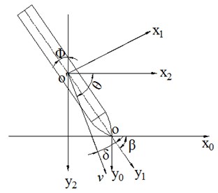
Fig. 4Force diagram
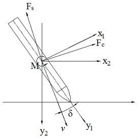
The initial attitude and force of the projectile penetration into concrete are shown in Fig. 3 and Fig. 4, the falling angle is , the oblique angle is , and the yawed angle is , and . Penetration resistances along and perpendicular to the axis of projectile center are and . Penetration resistance along the horizontal direction is and along the vertical direction is . The moment of inertia of the center of mass of the center of the incident plane perpendicular to the incident plane is . The angular acceleration is . The torque perpendicular to the incident plane quality spindle is .
In coordinate system , the motion equation of the center of mass is:
The axial component of velocity in the coordinate system is:
Differential the upper type and obtain:
At last we can give:
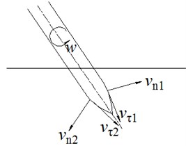
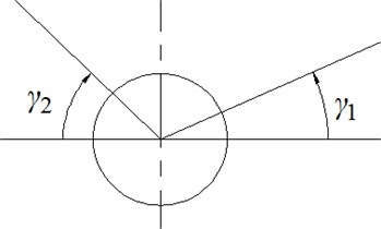
The rotational angular velocity of projectile on the mass axis is . The normal velocity and tangential velocity are respectively:
where , clockwise is negative; is the angle between the normal direction of concrete and the projectile axis; is the angle between normal direction and the plane, range in –90°-90°; “±” express the upper and lower surfaces of projectile, “+” is the upper surface, shown in Fig. 5.
Fig. 5Velocity distribution on contact surface
2.3. Surface normal stress
The normal stress is [11]:
where, . . Cavity expansion velocity is , and ρ is the destiny of concrete, and is wave propagation velocity. is modulus of elasticity in shear, is shear yield strength, and is the residual strength of fractured medium.
2.4. Penetration resistance analysis
According to surface spalling mechanism and force decomposition, normal force and tangential force in any element are:
The normal force and tangential force are projected to -axis and -axis are:
Take Eq. (18) and (19) into the Eq. (20) and (21):
The resistance moment in -axis is:
The resistance moment in -axis is:
where is radius of projectile circumference:
where is radius of projectile;is curvature radius of projectile nose; is length of projectile nose; is length between nose tip and mass center.
The ricochet process is divided into four stages as shown in Fig. 6: first stage, only part of the projectile nose into the target; second stage, some parts of projectile nose and rod penetrating into target; third stage, projectile nose completely penetrating into the concrete target, and part of rod into target; last the projectile jumps out. In order to facilitate the calculation of the resistance, the surface of the target body is projected into the center of mass of the projectile. The black dots stand for the mass center of projectile, just a sign, no meaning.
The surface element is defined in -axis:
can be defined as:
Fig. 6Ricochet process
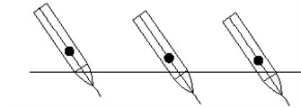
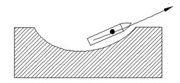
Fig. 7Geometric shape
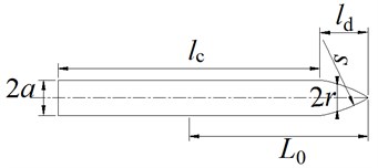
The geometrical relationship of projectile can be gotten by the Fig. 7:
The normal velocity and tangential velocity are respectively:
The resistances and torques in -axis and -axis.
When :
When , :
At last the resistance and torques are:
2.5. Solution and analysis of motion equation
The resistance torque in the mass center is:
The projectile’s penetration resistances are obtained by projection and to the center of projectile:
The differential equation of motion of the projectile nose:
where and are the horizontal displacement and vertical displacement.
2.6. Analysis of the calculation results
The projectile and concrete material coefficients are used from Chen [3], the weight of projectile is 5.9 kg, the diameter is 76.2 mm, and the curvature ratio was 4. The shear yield strength of concrete is 95 MPa, the density is 2240 kg/m3, the locking compression volume strain is 0.04. Calculation of rigid projectile oblique penetration into concrete target is taken by MATLAB program, which is shown in Fig. 8.
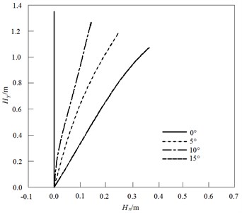
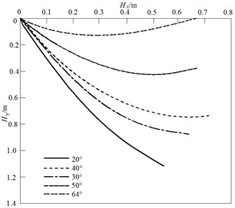
In Fig. 9, with the increase of the oblique angle, the nose trajectory is also more curvature. When the angle reaches a certain value, the ricochet occurs. The fundamental reason of ricochet is the deflection moment. The projectile cannot penetrate into concrete to a certain depth when the oblique angle is large. The resistance direction has not been swept through the center of the projectile. At this time, the projectile will ricochet in overturning moment under the action of (Fig. 10). If the projectile velocity is large, the bullet is not too late to turn a large angle on the concrete depth of the intrusion into concrete. At this point, the direction of the target's resistance is turned on the direction of the target’s resistance to the projectile. Target resistance force make decreased gradually. When the direction () changes, the moment of projectile into concrete become positive. Ricochet is mutual restriction of the initial incident velocity and initial angle of incidence. The initial specific incident angle in the 64° is not within the ricochet phenomenon, when the incident angle is greater than certain 64°, with the increasing of the initial oblique angle, ricochet phenomena are more likely, for initial specific incident angle, initial velocity is smaller, more prone to ricochet phenomenon.
Fig. 8Program flow diagram
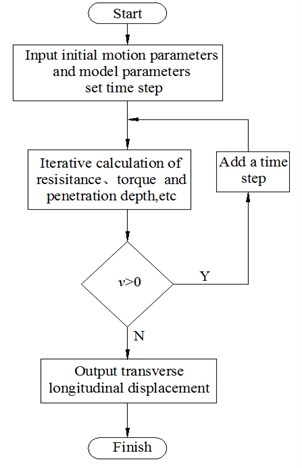
Fig. 9Trace of the tip of the projectile
3. Experimental research
Two kinds of projectile structure with different internal depths, flat nose and ogive nose are designed in the experiment to ensure equivalent quality (Fig. 11). The projectiles have a diameter of 10 mm, and a weight of 80 g. The shell material is 35CrMnSiA high-strength alloy steel, with yield strength of 1500 MPa. The hardness value is 45 after quenching. C40 concrete is used as target. The coarse aggregate is limestone aggregate, with an average particle size of 5 mm. The grade of the ordinary porland cement that was used in the experiment is PO42.5. Fine aggregate includes quartz sand. The quality ratios of cement, sand, coarse aggregate and water are 1:1.2:2.2:0.4. The diameter of the target is 500 mm, which is 50 times the diameter of the projectile, to reduce the influence of the side effect of the target body. The thickness of the target is 300 mm to approximate a semi-infinite thick target. The target plate periphery has a 3 mm thick steel plate to ensure convenient pouring of the concrete target and penetration. Three test pieces with dimensions of 150 mm×150 mm×150 mm are made in process of pouring the concrete target. Casting and maintenance are performed according to standard specification. The concrete targets meet the C40 requirement after the maintenance and static mechanical performance test (Fig. 12). A 25 mm caliber smoothbore gun is used as the launch platform for the projectile penetrating concrete target test. The field test arrangement is shown in Fig. 13. The propellant uses 5/7 powder. The velocity of the projectile is charge controlled, and measured by tinfoil target and double channel test instrument.
Fig. 10Deflection torque versus time
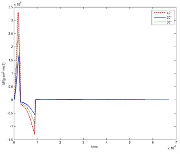
Fig. 11Photo of projectiles
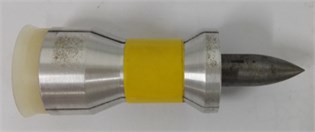
a) Ogive nose
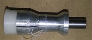
b) Flat nose
Fig. 12Concrete target
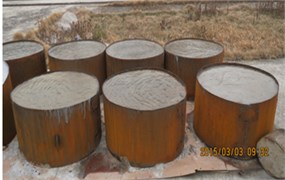
Fig. 13Experiment layout
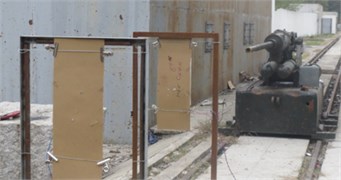
The oblique experimental results are also taken and the results are shown Fig. 14. The target marks can be seen from the paper, which indicate that the projectile is perpendicular to the concrete target. There is no obvious crack on the back of the concrete plate, which can be approximated to a semi-infinite target. The projectiles have no obvious plastic deformation except the nose, so it can be used to analyze the assumption of rigid projectile. The target plate is formed in the inlet funnel pit, which is about two times the size of the projectile.
The direction of resistance and the body movement are inconsistent, when the projectile suffers the resistance of the target in the process of oblique penetration into concrete. This inconsistency leads to constant changing of the body. The movement direction of the body deviates from the direction of the target surface. The projectile flies out of the target surface, and then ricochets. The ricochet occurs when the oblique angle of the flat projectile is 51°, reaching a speed of 805 m/s. Experimental data of the projectile ricochet is shown in Fig. 15, which shows that the projectile intrudes into the target after ballistic deflection from outside the target surface. The included angles of ricochet trajectory and target surface normal are large. Concrete materials after ballistic deflection in the local impact region are shed because of free surface tension action, and elliptical craters begin to occur.
Fig. 14Oblique penetration results
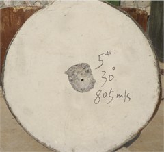
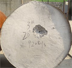
Fig. 15Ricochet
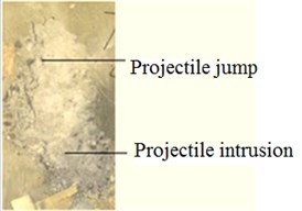
a) Photo of ricochet experiment
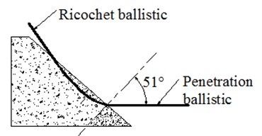
b) Diagram of ricochet
Experimental results of projectile penetrating into concrete target with different nose shapes are shown in Table 1.
Table 1Ricochet angle of projectiles with different nose shapes
Nose shape | 805 m/s | 925 m/s | 1020 m/s |
Flat | 51° | 57° | 64° |
Ogive | 58° | 64° | 69° |
4. Finite element model
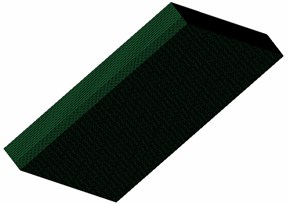
The calculation models of projectiles with different noses penetrating a concrete target are established (Fig. 16); the unit is mm. The 1/2 model is used in the calculation to save computation time and use of the symmetry of the structure. The target plate is set to a fixed constraint, and the projectiles and the target body are used for symmetric boundary conditions in the fourth week. The calculation was performed using Lagrange algorithm with hexahedral elements of the model grid, projectile nose, and target plate by impact regional grid refinement. Single point integral and hourglass controls are also used to reflect the nonlinear problems such as large deformation and material failure. The contact type in the model is surface-to-surface contact, adding failure criteria in contact algorithm. The static and dynamic friction coefficient of the contact is 0.15 and 0.1. The finite element model is shown in Fig. 17. The projectile and concrete targets are meshed by eight node hexahedron solid element (3D-Solid164). The shell of projectile is divided by sweeping method, and the internal loading and target are divided by mapping method. The area of the concrete passed by the projectile carries on grid encryption processing. The concrete grid mesh should close as possible mesh.
Fig. 16Diagram of projectiles with different nose shapes
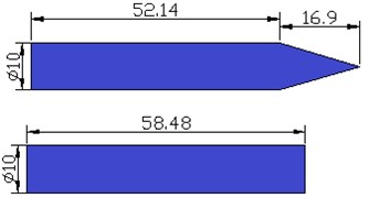
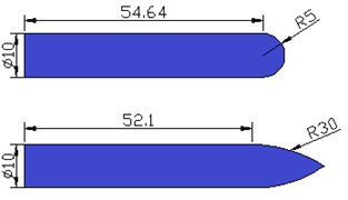
Fig. 17Finite element model

The projectiles apply the ideal elastoplastic model and parameters are shown in Table 2. The concrete target applies HJC strength model and Gruneisen state equation. The normalized equivalent stress is defined as:
where defines the actual equivalent stress, and is the quasi-static uniaxial compressive strength. The expression is defined as:
where is the damage parameter, is the normalized pressure and is the dimensionless strain rate. The model accumulates damage from equivalent plastic strain and plastic volumetric strain, and is expressed as:
where and are the equivalent plastic strain and plastic volumetric strain, respectively, and are material constants and is the normalized maximum tensile hydrostatic pressure.
The pressure for fully dense material is expressed as:
where , , and are material constants. The modified volumetric strain is defined as:
where defines the locking volumetric strain.
The Gruneisen equation of state with cubic shock velocity-particle velocity defines pressure for compressed materials as:
where is the intercept of the - curve, is the Gruneisen gamma, and is the first-order volume correction to .
The material parameters [12] are shown in Table 3.
Table 2Parameters of projectile material model
/ GPa | / kg/m3 | / MPa | / MPa | / (%) | |
204 | 0.33 | 7850 | 1900 | 15000 | 2.15 |
Table 3Parameters of concrete material model
/ (g/cm3) | A | B | N | C | / GPa | / GPa | |||
2.4 | 0.79 | 1.6 | 0.61 | 0.007 | 0.048 | 7 | 14.86 | 0.04 | 1 |
/ GPa | / GPa | / GPa | / GPa | / GPa | / GPa | / GPa | |||
0.01 | 0.016 | 0.0011 | 85 | –171 | 208 | 0.8 | 0.1 | 0.004 | |
5. Analysis of experiment and simulation results
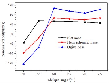
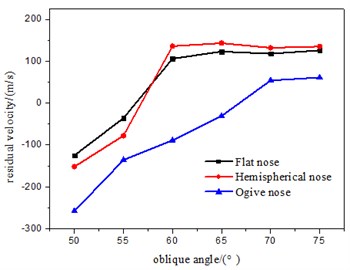
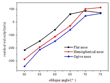
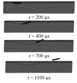
LS-DYNA software is used to calculate the ricochet with three different head shapes. Fifty-four cases of calculation for analysis of ricochet phenomenon in the penetration process are carried out with speeds of 800, 900, and 1000 m/s; the angles are 50°, 55°, 60°, 65°, 70°, and 75°. Fig. 18 shows the relationship between the velocity of the projectile and the angle of the initial surface of the concrete target at 800 μs. The target surface is vertical and pointed upwards, and the velocity component is positive. The component of the residual velocity in the vertical direction reverses if ricochet occurs, and velocity components turn from negative to positive. Fig. 18 indicates that the flathead bouncing bomb has a critical angle at approximately 50° when the speed is 800 m/s. The ricochet phenomena occur in flat-nosed projectiles when the oblique angles are from 50° to 70°. The critical angles of ricochet with hemispherical and ogive heads was 51° to 56° and 56° to 61°. The speed is 900 m/s, the critical angles of projectiles with flat, hemispherical, and ogive noses are 53° to 58°, 55° to 60°, 60° to 65° respectively. The speed is 1000 m/s, the ricochet critical angles with three kinds of projectiles head shapes are 60° to 65°, 65° to 70°, 65° to 70°. Fig. 18 shows that the flat-nosed projectile is embedded under some working conditions, and the residual velocity is positive. Moreover, the flat-nosed projectiles have residual velocity, the direction of velocity changes, and the movement direction jumps.
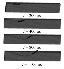
The simulation calculation and experiment results are consistent. The critical angle range of different head shapes of a projectile ricochet is shown in Table 4, which indicates that the ricochet critical angles of the projectiles with different head shape gradually increase gradually as speed increases, and the ricochet critical angle of the flat-nosed projectile is smaller than that of the hemispherical projectile. The pointed projectile achieves a large ricochet critical angle. Fig. 19 is maps of penetration and ricochet at different velocity. When the initial velocity is ensured, the greater the oblique angle, initial penetration time corresponds to the time course of the time between ricochet is shorter, the more prone to ricochet phenomenon. The displacement curve changes with time indicate the incident angle increases, the vertical displacement of projectile decreases corresponding ricochet phenomenon time, the lateral displacement increases. Also the smaller the oblique angle, kinetic energy by mechanical power consumption is bigger, so the residual velocity of the projectile.
Fig. 18Relation between residual velocity and oblique angle
a)800 m/s
b)900 m/s
c)1000 m/s
Fig. 19Ricochet of flat-nosed projectiles
a) 900 m/s, 65°
b) 1000m/s, 70°
Table 4Ricochet angle range of projectiles with different noses at different velocities
Nose shape | 800 m/s | 900 m/s | 1000 m/s |
Flat | About 50° | 53°-58° | 60°-65° |
Hemispherical | 51°-56° | 55°-60° | 65°-70° |
Ogive | 56°-61° | 60°-65° | 65°-70° |
Conical | 53°-57° | 57°-63° | 64°-70° |
6. Orthogonal test analysis of factors that influence ricochet
The variance analysis of the results of multi factor orthogonal test, usually first calculating the difference between the factors and the error of the square sum, and then calculate the factors and the degree of freedom, the mean square, F-measure, backward F test, analysis of significant. The above analysis presents that nose shape and speed affect the process of penetration and ricochet. The orthogonal test analyzes the specific indicators of primary and secondary relations in the three affecting factors. Ogive, hemispherical and conical nosed are selected. The materials are aluminum alloy, 35CrMnSi, and tungsten alloy. The material yield strength and hardness increase. The orthogonal design test analyzes the effects of nose shape, material, and speed on ricochet angle . Ricochet angle () is considered for indicators, and the investigated factors are nose shape, material, and velocity. Each factor has three levels, which are shown in Table 5.
Table 5Factors and value of each factor for orthogonal test
Level | Factors | ||
Nose A | Material B | Velocity C | |
1 | Conical | Aluminum alloy | 800 |
2 | Hemispherical | 35CrMnSi | 900 |
3 | Ogive | Tungsten alloy | 1000 |
Table 6Orthogonal experimental scheme and experimental results
Project | A | B | C | / (°) |
1 | 1 | 1 | 1 | 51 |
2 | 1 | 2 | 2 | 57 |
3 | 1 | 3 | 3 | 63 |
4 | 2 | 1 | 2 | 53 |
5 | 2 | 2 | 3 | 59 |
6 | 2 | 3 | 1 | 67 |
7 | 3 | 1 | 3 | 65 |
8 | 3 | 2 | 1 | 68 |
9 | 3 | 3 | 2 | 69 |
Sum I | 171 | 172 | 179 | |
Sum II | 179 | 181 | 183 | |
Sum III | 202 | 199 | 190 | |
Average I | 57 | 57.3 | 59.6 | |
Average II | 59.6 | 60.3 | 61 | |
Average III | 67.3 | 66.3 | 63.3 | |
Range R | 10.3 | 9 | 3.7 |
The factors and levels of Table 5 indicate that this experiment is a three-factor and three-level orthogonal test; thus L9 (34) orthogonal table is chosen. The model parameters show that the parameters are filled in L9 (34) table. The three-factor and three-level orthogonal design table is shown in Table 5. The above analysis indicates that the range analysis can be obtained by the different factors of the impact of the index. Table 6 presents the range analysis of the A, B, and C factors at different conditions. The range of various factors is the difference between mean value and minimum value.
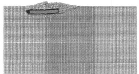
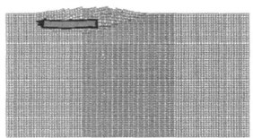
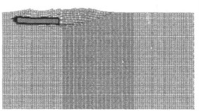
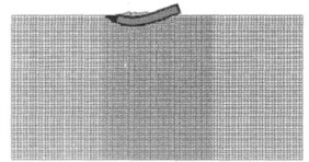
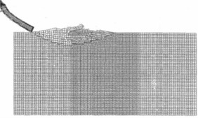
Range is large, thereby indicating a high influence degree of the factors. The primary and secondary order of factors is A, B, C. Factor A (nose shape) has the maximum effect on ricochet. B (material) has a secondary influence, and factor C (velocity) has a minimal effect on projectile ricochet angle. Index changes are shown in Table 6. The ricochet process are shown in Fig. 20 and Fig. 21, it indicates that the ricochet angle increase with the velocity increasing.
The nose shape of the projectile is ogive, the material is tungsten alloy, and the speed is 1000 m/s. The ricochet angle is the biggest, thereby indicating the strongest anti-ricochet ability. The experiment and simulation results have good agreement and illustrate the feasibility of the orthogonal experiment results.
The ricochet angle calculation of the projectile with ogive nose is calculated, and materials for 35CrMnSi penetrating a concrete target is carried out at medium velocity. Results are shown in Table 7. The fitting curve shown in Fig. 22 is based on the calculation performed by using by quadratic polynomial fitting in Table 7.
Fig. 20Ricochet (800 m/s)
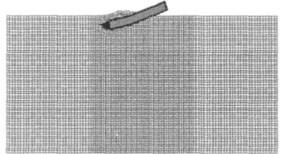
a) Time = 594 ms
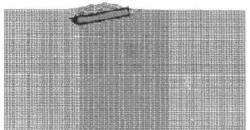
b) Time = 875 ms
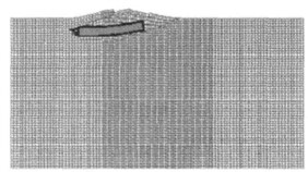
c) Time = 1128 ms
d) Time = 1374 ms
e) Time = 1589 ms
f) Time = 1978 ms
Fig. 21Ricochet (1000 m/s)
a) Time = 355 ms
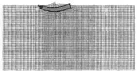
b) Time = 689 ms
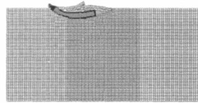
c) Time = 835 ms
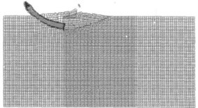
d) Time = 1025 ms
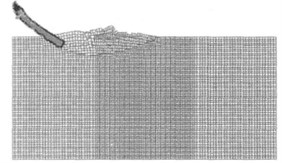
e) Time = 1343 ms
f) Time = 1501 ms
The variation function relationship between ricochet angle and penetration velocity is:
The law of ricochet angle and penetration velocity indicates a high penetration velocity, a strong anti-ricochet ability, and a large ricochet angle of projectile.
Fig. 22Ricochet angle and velocity
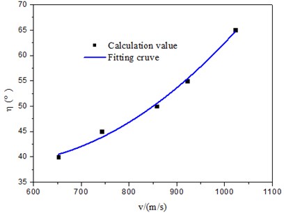
Table 7Ricochet angle at different velocities
/ (m/s) | 652 | 743 | 858 | 922 | 1022 |
/ (°) | 40 | 45 | 50 | 55 | 66 |
7. Conclusions
The mathematical model of ricochet is established according to the kinetic and surface layer mechanism; the ricochet trajectory of projectile is obtained. Flat-, hemispherical-, conical-, and ogive-nosed projectiles that penetrate a concrete target are studied based on experimental results. The ricochet rules of different materials, nose shapes and velocities are analyzed. The main conclusions are as follows:
1) The projectile produces a deflection torque leading to ricochet in the penetration process, which is caused by the oblique penetration and the asymmetric force of the projectile. The penetration depth increases with the increase of initial angle, and the deflection degree of the projectile is also increased. The emergence of ricochet phenomena is evidently restricted by penetration velocity and oblique angle. With the increase of oblique angle, ricochet phenomena are also more likely to occur at a certain angle. A smaller initial velocity corresponds to a higher likelihood of ricochet phenomenon.
2) The variation laws of the critical angle of ricochet are obtained via analyzing residual velocity according to different nose shapes of projectiles. The ricochet critical angles of different projectiles increase gradually as speed increases. The ricochet critical angle of a flat-nosed projectile is smaller than that of a hemispherical-nosed projectile. The ricochet critical angle of an ogive-nosed projectile is the smallest. The velocity is high, the anti-ricochet ability is strong, and the ricochet projectile angle is large.
3) The ricochet laws of factors, such as nose shape, material, and velocity, are given by orthogonal method. Significant influence ranking is based on nose shape, material and velocity.
This paper mainly discusses the influence of different nose shapes of projectile on the penetration rules. The scope of the critical angle of ricochet is presented. The nose shape of projectiles will be optimized in the future to improve penetration ability.
References
-
Qian Weizhang Mechanics of Perforation. Nation Defense Industry Press, Beijing, 1984.
-
Goldsmith W. Non-ideal projectile impact on targets: review. International Journal of Impact Engineering, Vol. 22, Issue 2, 1999, p. 95-395.
-
Chen X.-W., Li. Q.-M. Deep penetration of a non-deformable projectile with different geometrical characteristics. International Journal of Impact Engineering, Vol. 27, Issue 6, 2002, p. 619-637.
-
Li Jinghai Semi-armor-piercing blast of anti-ship missile warhead damage effects. Cruise Missile, Vol. 7, 2005, p. 52-55, (in Chinese).
-
Segletes S. B. A model for rod ricochet. International Journal of Impact Engineering, Vol. 32, 2006, p. 1403-1439.
-
Yu Wenli, Wang Tao, Dong Liang Computation of ricochet angle for oblique penetration of warhead into concrete targets. Journal of Projectiles, Rockets, Missiles and Guidance, Vol. 28, Issue 5, 2008, p. 109-112, (in Chinese).
-
Wu Rongbo, Chen Zhigang, Wang Qinghua Numerical simulation on the impact effect of incidence angle impacting ricochet. Design and Research, Vol. 10, 2011, p. 18-20, (in Chinese).
-
Guo Liuwei, Tan Duowang Numerical studies on the oblique penetration behavior of the projectile with cutting mechanism into a steel target. Chinese Journal of High Pressure Physics, Vol. 27, Issue 6, 2013, p. 833-838, (in Chinese).
-
Hu Dean, Li Xia, Liang Chao Research on ricochet and its regularity of projectiles with different nose shapes penetrating steel target. Chinese Journal of Applied Mechanics, Vol. 29, Issue 6, 2012, p. 752-756, (in Chinese).
-
Ning Jianguo Explosion and Impact Mechanics. National Defense Industry Press, Beijing, 2010, (in Chinese).
-
Forrestal M. J., Altman B. S., Cargile J. D., et al. An empirical equation for penetration depth of ogive-nose projectiles into concrete targets. International Journal of Impact Engineering, Vol. 42, Issue 9, 1994, p. 395-405.
-
Zhang Fengguo, Li Enzuo A computational model for concrete subjected to large strains, high strain rates, and high pressures. Explosion and Shock Waves, Vol. 24, Issue 5, 2002, p. 198-202, (in Chinese).
About this article
We gratefully acknowledge Professor W. F. Guo (Shenyang Ligong University) for revising the manuscript and Professor Z. X. Huang (Nanjing University of Science and Technology) for the valuable advice and discussions.

