Abstract
A vibration-based method for damage identification was established based on the “weak” formulation of Pseudo-excitation (PE) technique. The method can be effectively conducted without any prior knowledge of structural baseline parameters, e.g., Young’s Modulus, and is capable of detecting multi-damage in both one- and two-dimensional structural components. Moreover, relying on point-wise examination of structural dynamic equilibrium conditions, the baseline parameters of inspected structure can be inversely estimated in a statistical way, showing promising potential in engineering practices. As a proof-of-concept investigation, multi-damage in a plane structure, containing both beam and plate components, were identified experimentally using the proposed method.
1. Introduction
In recent decades, vibration-based damage identification methods have been intensively studied and widely applied in engineering practices [1, 2]. The effectiveness of traditional vibration-based methods, however, largely depend on the obtainment of benchmark structures and baseline signals established numerically or even experimentally, largely hampering the accuracy and efficiency of damage identification. To circumvent such a drawback, Pseudoexcitation (PE) technique was proposed by the authors [3, 4]. Residing on local examination of structural dynamic equilibrium conditions, the PE technique can be used to detect damage with high accuracy, independent of any baseline signals and benchmark structures. However, the reliance on some baseline parameters of target structures (Young’s Modulus, density, and various geometric parameters, etc.) cannot be prevented.
The PE technique was modified in recent study by assuming point-wise satisfaction of dynamic equilibrium along beam structure [5]. With the assistance of advanced signal processing techniques, e.g., continuous wavelet transform (CWT), the location of structural damage can be clearly identified without the prior knowledge of structural baseline parameters. Moreover, the baseline parameters can be inversely estimated in a statistical way, showing valuable potential in engineering applications.
In this study, the application of the modified PE technique was extended, capable of characterizing multi-damage in two-dimensional structures. The two-dimensional damage index was established based on the “weak” formulation of traditional PE technique [6], relying on which damage feature can be largely highlighted with effectively reduced noise influence. As a proof-of-concept investigation, multi-damage in a plane structure, containing both beam and plate components, were identified experimentally using the proposed method. And the estimated value of the baseline parameter was compared with the exact value.
2. Modified PE technique based on “weak” formulation
The two-dimensional damage index of traditional PE technique can be expressed as [4]:
where:
In the above equations, w(x,y) is the vibration displacements; D is the bending stiffness equal to eh3/12(1-v2); E, ρ, v, h and ω are the Young’s Modulus, density, Poisson’s ratio, thickness and angular vibration frequency of the plate, respectively.
It is obvious that a variety of baseline parameters, including Young’s modulus and various geometric parameters, should be known in order to construct Eq. (1a). To eliminate the dependence on structural baseline information, Eq. (1a) is modified as:
where λ*=ρhω2/D. It can be seen that all the baseline parameters are include in λ*.
To reduce the influence from measurement noise in experimental circumstance, the “weak” formulation of PE technique was proposed in previous study [6], with two-dimensional expression written as:
where η(x,y) is a weighting function; Ξ is a two-dimensional region for the integration operation. Based on Eq. (2b), the noise influence can be effectively averaged within Ξ, leading to highlighted damage feature. By changing the size of Ξ, the effect of noise reduction and accuracy of damage identification can be adjusted.
3. Statistical estimation of structural baseline information
In practical applications, assuming there are m points on the inspected plate surface, where the vibration displacements are measured, and at a point of without damage existence, Eq. (2b) becomes:
And according to Eq. (2a), λ* can be derived according to:
At damaged regions, Eq. (3a) does not actually hold, and λ* will show fluctuated distribution along the plate. The values of λ* will converge to the exact value statistically. Thus, depending on Eq. (3b), λ* can be inversely estimated based on structural vibration displacements, and the damage index expressed in Eq. (2b) can be constructed.
4. Experimental validation
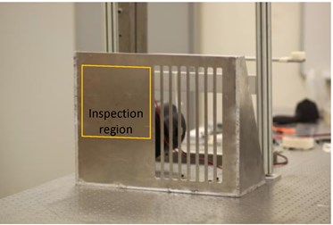
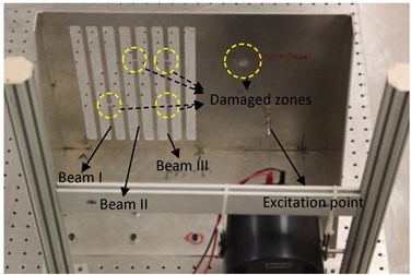
A plane structure containing both plate and beam components is shown in Fig. 1(a) and (b). All panels of the structure, with thickness of 3 mm, were made up of Aluminum 6061 with Young modulus of 6.89×10¹⁰ Pa, mass density of 2.7×10³ Kg/m3, and Poisson’s ratio of 0.27. It can be seen that there are five damage zones at the back side of the structure, including four notches (with lengths of 4 mm and depths of 1.3 mm) on three beam components and one square damaged zone on the plate component (with side length of 8 mm and depth of 1.3 mm). The surface of the structure was excited under vibration frequency of 1800 Hz, and a laser scanning vibrometer (Polytec® Scanning Vibrometer, PSV-400) was used to scan the vibration displacements of the front surface. A square inspection region (with side length of 0.21 m) was selected on the plate component to include the square damaged zone. And the vibration displacements of the inspection region were shown in Fig. 2(a), it can be calculated that the wavelength of the vibration of the plate component, defined as γ, is approximately 0.21 m.
Fig. 1a) Front and b) back view of the plane structures
a)
b)
Fig. 2Distributions of a) vibration displacements and b) damage index constructed using Eq. (1a), within the inspection region of the plate component
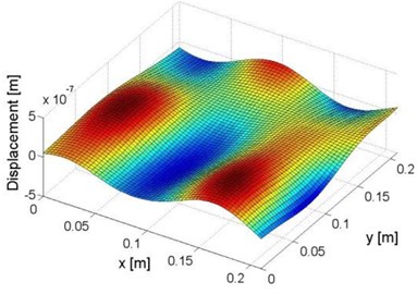
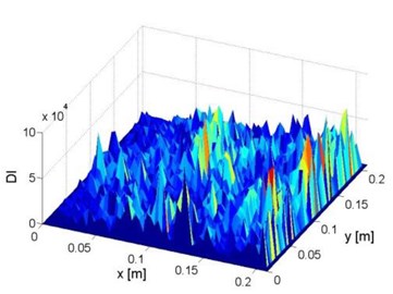
Using the measured vibration displacements in Fig. 2(a), the constructed damage index according to Eq. (1a) is shown in Fig. 2(b). It can be seen that even based on the baseline parameters of tested structure, the constructed signal is unable to reflect any feature related to the damaged zone because of the serious influence from measurement noise.
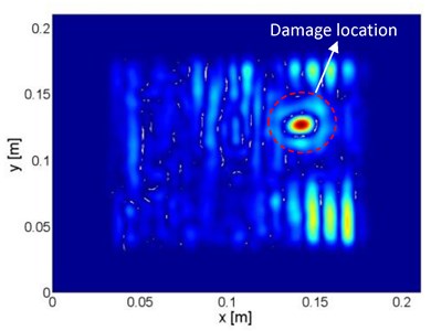
The modified PE technique based on “weak” formulation was then applied to identify the damage locations. Ξ in Eq. (2b) is set to be a square region, the side length of which is defined as d. the position of Ξ was adjusted along the plate surface. At every position, λ* was calculated according to Eq. (3b). Subject to d/γ= 0.4, the distributions of λ* are shown in Fig. 3. Some abnormal values are deemed as outliers distributing outside a pre-defined bandwidth (10 % of the standard deviation of the entire data), and were excluded. Then, λ* was estimated as the average value of the remaining data. The estimated λ* is 10 % larger than the exact value, the error of estimation comes from the influence of measurement noise. Finally, by using the estimated λ*, ˉI(x,y) was calculated according to Eq. (2b), as shown in Fig. 4(a). It can be seen that the location of the damaged zone on the plate component can be clearly identified.
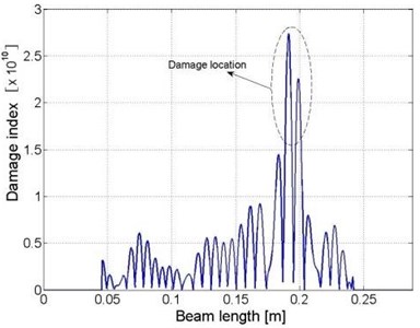
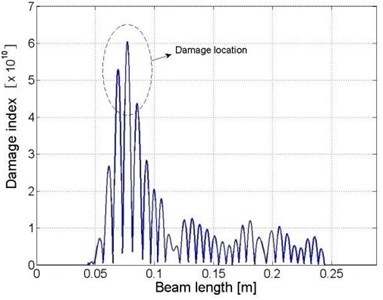
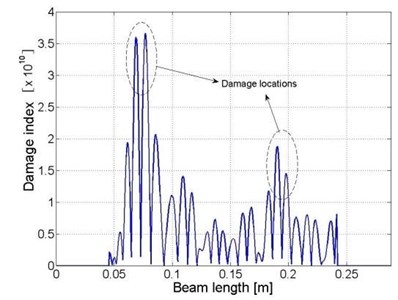
The locations of the damage zones in the beam components can be calculated similarly, according to the one-dimensional “weak” formulation for beam structure. The identification results are presented Fig. 4(b) to (d), respectively.
Fig. 3Distribution of λ* within the inspection region of the plate component
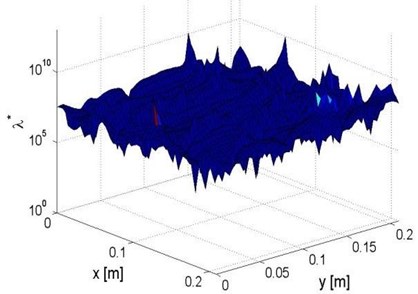
Fig. 4Distributions of damage indices within a) the plate component and b) beam I, c) beam II and d) beam III
a)
b)
c)
d)
5. Conclusions
It was demonstrated in the presented study that the PE technique, with its “weak” formulation, can be effectively used to detect damage in one- and two-dimensional structures without any prior knowledge of structural baseline information. By assuming the point-wise satisfaction of dynamic equilibrium conditions, the baseline parameters can be inversely estimated statistically. It can be observed from the experimental results that the method is able to reveal damage location with satisfactory accuracy. It is anticipated that based on multi-tests under different frequencies, the detection accuracy can be further improved by using data fusion scheme. Moreover, the error of estimating the baseline parameter is mainly attributed to measurement noise. Advanced signal processing technique should be adopted in further study aimed at increase the accuracy of parameter estimation.
References
-
Farrar C. R., Doebling S. W., Nix D. A. Vibration-based structural damage identification. Philosophical Transactions: Mathematical. Physical and Engineering Sciences, Vol. 359, Issue 1778, p. 131-149.
-
Fan W., Qiao P. Vibration-based damage identification methods: a review and comparative study. Structural Health Monitoring: an International Journal, Vol. 10, Issue 1, 2011, p. 83-111.
-
Xu H., Cheng L., Su Z., Guyader J.-L. Identification of damage in structural components based on locally perturbed dynamic equilibrium. Journal of Sound and Vibration, Vol. 330, 2011, p. 5963-5981.
-
Xu H., Cheng L., Su Z., Guyader J.-L. Damage visualization based on local dynamic perturbation: theory and application to characterization of multi-damage in a plane structure. Journal of Sound and Vibration, Vol. 332, 2013, p. 3438-3462.
-
Xu H., Su Z., Cao M. S. Dynamic perturbation characteristics for non-baseline structural damage diagnosis. Journal of Vibroengineering, Vol. 17, Issue 4, 2015, p. 1796-1804.
-
Xu H., Cheng L., Su Z., Guyader J.-L. A pseudo-excitation approach for damage identification: from “strong” to “weak” modality. Journal of Sound and Vibration, Vol. 337, 2015, p. 181-198.
About this article
This project is supported by the Hong Kong Research Grants Council via General Research Fund (GRF) (Nos. 15214414 and 523313).
