Abstract
Unreasonable trajectory is the main factor that limits the stable motion of the carrier of maypole braiding machine. The kinematical model of the carrier is established. The acute change of the load causes severe vibration of the carrier in the straight line segment of the “”-shape trajectory. Combination curve of modified trapezoid is used for optimizing trajectory. The result shows that the maximum dimensionless jerk of the carrier is decreased obviously. The trajectory of tangent equal circles (simplified TEC) is obtained in the optimization objective of minimum load fluctuation and leads to the vibration and noise of braiding machine be reduced notability. The design theory of machine has been provided in this research, which can improve the overall performance of the braiding machine.
1. Introduction
Maypole braiding machine is mainly used to manufacture braided rope, fiber bundle tube, insulation outsourcing yarn of wire and cable, reinforced layer of rubber tube, etc. The “”-shape trajectory limits the braiding speed, vibration and noise of the machine. The carrier of high speed braiding machine go along a circular trajectory. The braiding speed and performance are improved. However, the structure of the high speed braiding machine is complex. The parts of the high speed braiding machine have high requirements in dimensional accuracy and assembly accuracy, which lead to high cost [1]. Little research has been conducted in analyzing and optimizing the widely used maypole braiding machine. Ostermann provided synthetic plastic material at margins in the region of each sector, so as to reduce the noise resulting from engagement between the margins and the carrier [2]. Currently this sound-damping means is widely used in design of a passive damping noise reduction. Cimprich et al. invented the “sandwich” structure wherein a viscoelastic material is bonded to out plate members effectively reduces the noise in braiding machine [3]. Du et al. designed the interactive protruding track braiding machine, the seamless connection of the track is ensured, the impact force, friction force and noise can be reduced effectively [4]. Head et al. invented a braiding system which has a plurality of mobile carrier devices movable under its own power, and each of mobile carriers device is configured to determine its direction back to the virtual path altering course to avoid collision [5]. Jiao replaced traditional plane track with Centripetal disc track, reduced the oblique tension of the carrier produced by braided yarn in the braiding progress, and improved the braiding speed [6]. Tang applied magnetics suspension technology to reduce the wear between the carrier and the track [7].
The above researches neither analyze the kinematic characteristics of carriers thoroughly nor solve the big noise produced by unreasonable trajectory fundamentally. Maypole braiding machine is widely used in light industry. Optimizing unreasonable trajectory of carriers is beneficial to enhancing overall performance of the braiding machine.
2. Operation method of maypole braiding machine carrier
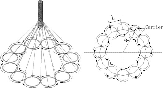
Maypole braiding machine carriers carry two groups of yarns running along a certain trajectory. One group of yarns (the warp yarns) move clockwise and another group of yarns (the weft yarns) move counter-clockwise, both of yarns have an equal angular velocity. The two groups of yarns interlock to form a hollow fabric as shown in Fig. 1. These trajectories are two generally circumferentially extending sinuous trajectories which crisscross each other.
Fig. 1Movement schematic diagram of carriers
3. Kinematics analysis of braiding machine carrier
3.1. Kinematics model of braiding machine carrier
1) Basic hypothesis:
(1) The mass of carrier components are equal.
(2) The trajectory units of carrier are same ignoring the machining error of track.
(3) The manufacture error, installation error and transmission error of parts are ignored.
(4) The friction coefficient between carriers and its track is constant.
(5) Horn gears have an equal angular velocity.
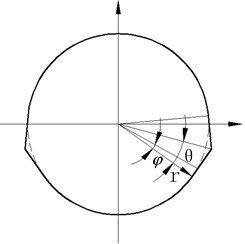
The trajectory units of the carrier are shown in Fig. 2. The carrier is regarded as a follower of cam mechanism. The cam rotates at a uniform speed, and the carriers move at nonuniform velocity along its trajectory at the same time.
Fig. 2Trajectory unit
2) Carrier displacement :
Carrier’s displacement is in the circular segment of trajectory. The displacement of the internal common tangent segment is:
where, is the radius of circle, is the angular displacement (rad) of the carrier in internal common tangent segment, which takes the tangent point as the starting point. The maximum is .
3) Carrier similar velocity is:
4) Carrier similar acceleration is:
5) Carrier similar jerk is:
When carriers move to the intersection point of the internal common tangent segment, its inertial acceleration is:
At the intersection point of internal common tangent segment variable quantity of the inertial force is:
where, is the mass of the carrier component, is the number of horn gears, is angular velocity of carriers.
3.2. Kinematics analysis of braiding machine carrier
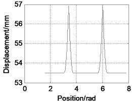
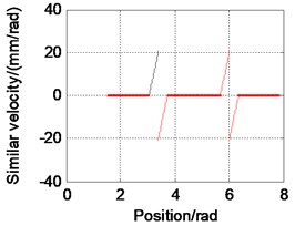
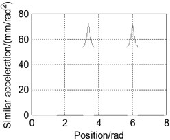
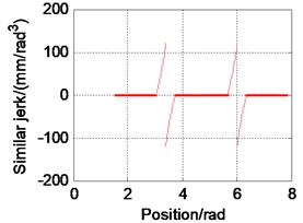
The kinematics analysis results of braiding machine carrier could be obtained from Eqs. (1)-(6), as shown in Fig. 3.
Fig. 3(a) shows the relationship between carrier displacement and different angle position. The carrier displacement is constant in the arc segment of trajectory and is nonlinear in the straight line segment of trajectory, and achieve the maxima at the intersection point of internal common tangent segment. Because of the symmetry of the carrier trajectory, displacement trend is symmetrical about the intersection point of the internal common tangent segment.
Fig. 3(b) shows the relationship between carrier similar velocity and different angle position. The value of the carrier similar velocity is zero in the arc segment of trajectory. Similar velocity trend of the straight line segment trajectory is symmetrical about the intersection point of the internal common tangent segment. According to the operation method of carriers, trajectory unit is formed by the movement of carriers which have oppositely direction. Then the direction of the similar velocity of carriers reversed when carriers move to the intersection point of the internal common tangent segment.
Fig. 3(c) shows the relationship between carrier similar acceleration and different angle position. The value of the carrier similar acceleration is zero in the arc segment of trajectory, which began to increase from the tangent point, and reach the maxima at the intersection point of the internal common tangent segment. Similar acceleration trend is symmetrical about the intersection point of the internal common tangent segment.
Fig. 3(d) shows the relationship between carrier similar jerk and different angle position. The value of the carrier similar jerk is zero in the arc segment of trajectory. Similar jerk trend is monotone nonlinear and also symmetrical about the intersection point of the internal common tangent segment in the straight line segment. Because of the symmetry of the carrier trajectory, the direction of similar velocity is reversed when carriers move to the intersection point of the internal common tangent segment.
Fig. 3Simulation result of carrier movement
a)
b)
c)
d)
4. Optimization of the trajectory
4.1. Kinematic characteristics of the trajectory for composite modified trapezoidal curve
Modified trapezoid curve can combine to form trajectory of carriers in that it can reduces the flexible impact on cam follower at the two ends of the constant acceleration movement and the junction of the positive and negative acceleration. Similar acceleration cure is modified trapezoid curve at the rise portion [8]. The division diagram of the rise and fall portion of the trajectory unit is shown in Fig. 4.
Fig. 4Trajectory unit combined by modified trapezoid curve
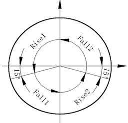
The waist of similar acceleration curve is a sine wave at the rise portion, and its motion angle takes up 1/8 of angle for rise portion. The motion angles of the constant acceleration and the constant deceleration all take up 1/4 of angle for rise portion. Therefore, the characteristic equations of rise movement are:
For :
where, is the displacement of the follower, is the angle of the rise portion.
For :
for :
For :
For :
Let the calculation datum of the fall movement equation is the same as the rise movement equation. Then characteristic equations of the fall movement are:
where, is the displacement of the rise movement, is the displacement of the fall movement. The rise movement equation can be substituted directly into the right of the equal sign of Eq. (12). Meanwhile, is replaced by and is replaced by . Therefore, characteristic equations of the fall movement are:
For :
For :
For :
For :
For :
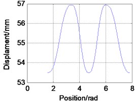
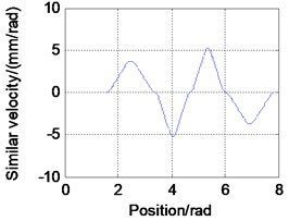
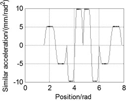
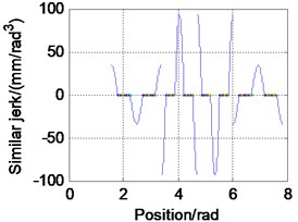
The kinematics analysis results of the braiding machine carrier could be obtained from Eqs. (7)-(17), as shown in Fig. 5.
Fig. 5(a) shows the relationship between carrier displacement and different angle position. According to the operation method of carriers, displacement curve is symmetrical about the initial point of Rise 1 (as shown in Fig. 4). The intersection point of the adjacent trajectory unit is the end point of the rise movement.
Fig. 5(b) shows the relationship between carrier similar velocity and different angle position. The value of the similar velocity is zero at the initial point and at the end point of rise movement, and its trend firstly increases and then decreases, and achieves maxima at the intersection point of the cycloid acceleration and the cycloid deceleration portion. The direction of similar velocity is positive at rise movement, and negative at fall movement.
Fig. 5(c) shows the relationship between carrier similar acceleration and different angle position. The value of the similar acceleration is zero when carriers move to the intersection point of the cycloid acceleration and the cycloid deceleration portion, the initial point and the end point of the rise movement. The similar acceleration trend is modified trapezoid curve, and its direction is positive at the rise movement, while negative at the fall movement.
Fig. 5(d) shows the relationship between carrier similar jerk and different angle position. The value of the similar jerk is zero at the constant acceleration and deceleration movement, and achieves the maxima when carriers move to the intersection point of the cycloid acceleration and cycloid deceleration portion and the initial point and the end point of the rise movement. The similar jerk direction is positive when the value similar acceleration rises up, and negative when the value similar acceleration falls down.
4.2. Kinematic characteristics comparison of the two trajectories
Evaluation parameters such as maximum dimensionless velocity , acceleration and jerk are always used to evaluate follower motion performance in the cam mechanism.
Trajectory of carrier is “”-shape curve:
where, is the angle of the rise portion, is the displacement of the rise portion.
Trajectory of carrier is modified trapezoid curve:
According to the related dimensions of the vertical braiding machine with 24 carriers, let the distance between mass center of the carrier and its rotation center equals 53.5 mm, the center distance of adjacent horn gears equals 110 mm, the distance between the center of horn gear and the center of track plate equals 220 mm, the value of is 9 rad, the number of horn gears is 12. The values of evaluation parameters of the two trajectories could be obtained by substituting the value of parameters into Eqs. (18)-(19). The results are shown in Table 1.
Table 1Performance parameters of the two trajectories
“”-shape trajectory | Modified trapezoid trajectory | |
11.0392 | 2 | |
±70.3092 | ±4.8881 | |
±214.8407 | ±61.4260 |
Safety production requires maximum momentum (product of and ) of the carrier be small. From Table 1, it is clear that the maximum momentum of modified trapezoid trajectory is smaller than that of the “”-shape trajectory. The additional load rate of carriers affects fatigue life of carriers and track plate. The additional load rate can be expressed as follows:
Eq. (20) indicates that additional load rate is positively correlated with similar jerk. Choosing the smaller value of can reduces the additional load rate. Table 1 shows that the additional load rate of the modified trapezoid trajectory is smaller than that of the “”-shaped trajectory.
Fig. 5Simulation result obtained by carrier movement
a)
b)
c)
d)
4.3. Trajectory optimization based on the minimum of the load fluctuation
The trajectory of carrier is shown in Fig. 6. The displacement can be written as:
where, is the radius of base circle, is the rotation angle of the carrier.
Fig. 6Trajectory diagrammatic sketch
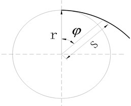
Then load fluctuation can be written as:
Mathematical model with the minimum load fluctuation optimization goal can be obtained as follows:
If is not varying with the change of the , the carriers will make uniform circular motion. Meanwhile, the theoretical value of the load fluctuation is zero. The tangent equal circles (simplified TEC) trajectory of the carrier is the most stable operation scheme.
5. Experimental research
The TEC trajectory is realized through using the carrier and the track plate as follows:
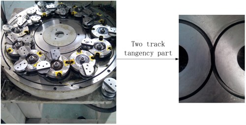
Both the deep track and the shallow track follow an “”-shaped curve which connect with each other ring array on the track plate. The center lines of tracks form the TEC trajectory. Guide pads respectively adapt to the two kinds of tracks. The track plate structure is shown in Fig. 7.
Fig. 7TEC trajectory braiding machine
The investigation method is used in the contrast test between the “”-shape track braiding machine of BFB24L-114B type and the tangent equal circles track braiding machine, under the condition of the same acoustic environment. The test point is located at the point of 1m just above the geometry center of the upper surface of the track plate. Noise levels are measured using a 1st class sound level meter (B&K2270) which performance parameters range are set as follows: Linear frequency response 4.2 Hz-22.4 kHz; A-weighted dynamic range 16.6-140 dB; Accuracy ±0.7 dB. The test results show that the average noise of single machine reduced from 83.5 dB to 82 dB when rated power is 1.1 kW and these carriers rotary speed is 45 r/min.
6. Conclusion
The kinematical model of the carrier is established in the research work. Modified trapezoid curve is used to optimize trajectory of carriers. The result shows that the load fluctuation of the carrier is decreased obviously. The TEC trajectory is obtained in the optimization objective of minimum load fluctuation, which is helpful to reducing the collision and wear between carriers and the track. The results of experiment show that the noise is decreased at the same rotary speed of the carrier. Therefore, the correctness of theoretical results is verified. However, the rotary speed of the carrier is restricted due to the serious local stress concentration of track plate showing in Fig. 7. The structure of track plate still needs to be further optimized.
References
-
Jiang J. B., Li J. P., Liu Y., et al. A comparison study of characteristics of performance of several steel braiders. Special Purpose Rubber Products, Vol. 33, Issue 6, 2012, p. 60-63.
-
Ostermann M. Braiding Machine. U.S. Patent 3,981,223, 1976.
-
Cimprich F. J., Boyd J. J., Wessner W. J. Jr. Braiding Machine. U.S. Patent 4,304,169, 1981.
-
Du B., Mao L. M., Hou C. J., et al. Interactive Protruding Rail Braiding Machine. China Patent CN201110165294.X, 2011.
-
Head A. A., Ivers V. M. Rapidly Configurable Braiding Machine. U.S. Patent 20140298768, 2014.
-
Jiao A. Q. Centripetal Disc Knitting Machine. China Patent CN201320664190.8, 2014.
-
Tang X. N. Coaxial Cable Maglev Flywheel No-Oil Low-Noise High Speed Braiding Machine. China Patent CN104376928A, 2015.
-
Peng G. X., Xiao Z. Y. The Design of Cam Mechanism of Automatic Machinery. Machine Industry Press, Beijing, 1990, (in Chinese).
About this article
This project was supported by a Grant from the Education Department Henan Province (Project serial number 14A460012). The authors also thank Xinchang Benfa Electromechica Co. Ltd. for the help in setting up the experiments and for the use of facilities. Work partially supported by Advanced Machinery and Equipment Manufacturing Collaborative Innovation Center in Henan Province.
