Abstract
Study of the rotating system dynamics by numerical methods requires an appropriate modeling of cooperation of shaft with bearings. The choice of method of modeling the bearing supports of shaft may have a significant impact both on the results obtained and the time needed to complete the simulation. The paper proposes a simplified way of modeling the bearing supports in rotating systems. The proposed modeling methodology is applied in the author’s library of Simulink blocks, which is dedicated to the research of simulation of rotating systems in transient states and in the presence of various types of non-linearity. The main purpose of applied simplifications is acceleration of simulation calculations while maintaining sufficient accuracy. The results of the simulation are presented on chosen example.
1. Introduction
In case of computer simulations of rotor dynamics phenomena an appropriate modeling of bearing supports is extremely important and affects obtained results. In real systems elastic bearing supports can alter the nature of vibrations. Same bearings (in particular slide) are also often source of motion instability, due to occurring damping phenomenon [1, 2]. Replacement of the bearings with perfectly rigid supports, in principle, is prohibited and may be a source of model mismatch to the test object.
The task of modeling the bearings in case of time-domain simulation also generates some numerical problems [3]. For rolling bearings, too accurate representation of bearings may adversely affect the length of the numerical integration step and increase simulation time. Low weight of the rolling elements and relatively high contact rigidity is such that in a typical case the frequency of vibration of the rolling elements may be up to several orders higher than the natural frequency of rigid rotors. Since the vibration of the rolling elements and the rotors are made at different time scales, it is difficult to effectively analyze both phenomena at the same time. If the purpose of simulation is to obtain information on the nature of the rotor vibrations, it is best to skip motion of the rolling elements even. Sometimes it is preferable also to block the relative motion of the inner race and the bearing housing. Sufficient then is to consider only vibrations of the housing with respect to elastic foundation. The housing typically has a larger mass in comparison to the mass of the rotating inner ring, and the foundation has a greater stiffness, which improves the matching frequency of vibration. For the same reason, not only the weight of the inner ring should be take into account in the dynamic model, but also weight of a shaft section mounted on the bearing.
In the literature many models of rolling bearings with varying degrees of complexity can be found, e.g. [4, 5]. Most of them replace bearing with the elastic damping elements of nonlinear or linearized characteristics [6]. There are also models highly complex, taking into account rolling elements vibration and nonlinearities resulting from elastohydrodynamic contact and internal clearances [7]. Also rich is the literature on sliding bearings and calculation methods of their parameters, for example [8]. Is also available the professional software that enables prediction of bearing dynamic parameters based on the assumed of geometrical characteristics [9].
In the FEM both types of rolling and sliding bearings are modeled mostly by supplementing dynamic equations of motion of the system with additional equations of the form [10]:
where K, D – are respectively matrices of stiffness and damping of the bearing defined in the global coordinate system, ui, fi – are displacement and generalized forces due to interaction of bearing in node number “i” of finite element mesh, transformed into the global coordinate system. Matrices K, D are included then in the aggregation process of the global stiffness matrix and damping.
It is known that contact phenomena are characterized by the relationship between the forces and the displacements of the form: F~√δ3. For this reason, the linearization of the contact stiffness is valid only when the bearing is fully operational (no clearances) and preloaded. In this case, the vibrations take place around a fixed position of the equilibrium and force-displacement relationship can be regarded as linear. However, stiffness matrix coefficients are depended on the nominal state of the bearing load.
Discussed below are two basic models of bearings, used in currently developed author’s Simulink library to study of nonlinear transient states of rotating systems of any configuration [11, 12]. These models are adapted to the proposed in [13] methodology for division of the rotating system into rigid and elastic-damping elements.
2. Modeling of the rotating system
The idea of division the rotating system into rigid and compliance elements, which is the basis of the above-mentioned library Simulink [9], is illustrated in Fig. 1.
Fig. 1Division of rotating system into rigid and elastic elements
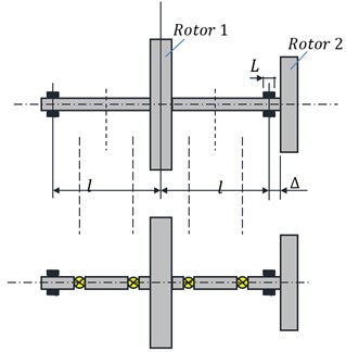
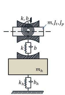
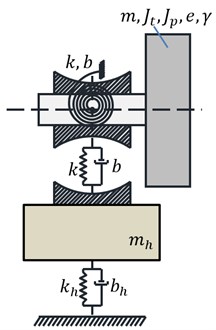
The library is built on the model of rigid rotor with six degrees of freedom with static and dynamic imbalance [10, 11]. The bearing is treated like a rigid rotor, with the difference that motion of rigid body representing the bearing is restricted by the contact forces resulting from the interaction of the bearing with housing. The general idea of constructing a dynamic model of the bearing is presented in Fig. 2. Depending on the distance of the bearing from the “big” inertial element (rotor) two cases of modeling are possible. In the first (left bearing in Fig. 1), the body representing movable part of the bearing can be treated as a rotor which is ideally balanced, and therefore use simplified equation of motion (the model on the left in Fig. 2). In the second (bearing on the right in Fig. 1) rotor is too close to the bearing. Dividing the shaft section between a lumped mass representing a bearing and a rotor number 2 introduces the elastic-damping element with a very high stiffness. This is a disadvantage, and better is to consider motion of body which is a combination of the shaft section and supported bearing with a rotor. However, in this case the more complex equations of motion of imbalanced rotor should be taken into account (model on the right in Fig. 2).
Fig. 2Two typical dynamic models of the bearing resulting from applied division of rotating system into stiff and elastic elements
a)
b)
3. Equations of motion of rigid body representing rotors
To describe the position of each body (inertial element of the rotating system), six generalized coordinates are necessary:
which corresponds to translational motion in the global coordinate system, the axis “z” coincides with the projected axis of rotation of the machine. On the axis “z” are geometric centers of rotors, shafts and other components of the rotating system, in an undeformed state, at rest. Rotating motion is described whereas in local systems ξ, η, ζ permanently associated with the inertial element using a set of Euler angles ψ, θ, φ, which form rotation 1-2-3. On each element act generalized forces generated by susceptible elements:
In many cases, it is more convenient to express these forces in the global coordinate system, for example when they are resulting from the elastic properties of the bearings.
The equations of motion of a rigid imbalanced rotor taking into account the coupling between the flexural, torsional and longitudinal vibration are quite complex, even after linearization. They are described together with a proposed method for their decoupling in the work of the author [10, 11]. The inertial decoupling procedure for such equations requires the calculation of coefficients of the respective matrix at each position – step of numerical integration.
When modeling the bearings, it is not always necessary to take into account imbalances. Typically, gyroscopic vibrations (an inclination of rotor’s plane described by angles ψ and θ) are very small. In such a case, one can use the equations of motion of the perfectly imbalanced rotor. The rotary equations of such a rotor, after linearization, replacing generalized forces by corresponding moments of force in the global coordinate system and rejection of terms containing products of ψθ take the form of [11]:
Jt¨θ-Jp˙φ˙ψ-Jp˙ψ2θ+Jt˙ψ2θ=My+ψMz,
Jp¨φ+Jp˙ψ˙θ-(J2pJt)˙φ˙θθ=Mz+Mxθ(1-JpJt)-Myψ,
where: Jt, Jp represent respectively transverse and polar moments of inertia.
4. Equations of bearing motion
On a rigid body obtained as a result of modeling, representing the movable part of the bearing, act forces related to the internal stiffness and damping in the bearing marked symbolically by FB. Other forces FL, FR come from shaft parts combined with the bearing. Symbols F determine in this case vectors of the six components expressed in the global coordinate system. If the bearing is sufficiently short, all these forces can concentrate directly in the center of the bearing B. Counter force to FB acts on the bearing housing. It is at once a dynamic response which can be significant when selecting the bearing.
Fig. 3Dynamic model of the bearing
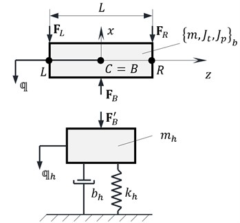
In order to simplify the model, it is assumed that housing motion takes place exclusively in lateral and is described by vector qh=[xh,yh,0,0,0,0]T.
If the Euler angles ψ, θ are infinitesimal small, they correspond to the respective angles of deflection in the global coordinate system. Then the dynamic response of the bearing can be calculated by the general formula:
where Kn is an optional matrix of nonlinear stiffness (usually n=3). Symbol (∙)n should be understood as “.^” in Matlab. Stiffness matrix of bearing can be adapted to the universal character of both types of bearings – sliding and rolling:
A similar structure is adopted for non-linear stiffness matrix and damping matrix. Coefficient kzz≠0 occurs only in resistive bearing. Stiffness of type kxy, kyx, occur only in sliding bearings, and then the stiffness matrix does not have to be symmetrical kxy≠kyx [8]. In the simplest case the rolling bearing K=diag(kxx,kyy,kzz,kϑxϑx,kϑyϑy,0).
Further, the dynamic forces may be complemented with a friction force, for example by using elementary friction model:
where μ, μt – friction coefficients, dB – the diameter of the inner race.
Excluding factors containing small angles ψ, θ, the equations of motion of the movable part of the bearing (Fig. 3) and the housing take an approximate form [11]:
¨θJt-˙φ˙ψJp=My,m¨y=Fy,
¨φJp+˙ψ˙θJp=Mz,m¨z=Fz,
mh¨xh+bhx˙xh+khxxh+knhxxnh=FBx,
mh¨yh+bhy˙yh+khyyh+knhyynh=FBy.
If the bearing is lying very close to the rotor as illustrated in Fig. 2(b), the equations of motion of imbalanced rotor should be applied instead of the first six Eq. (8).
5. Simplified method of modeling the bearing
The direct integration of equations of motion required during the study of transient states is very time consuming. Calculations can be accelerated by maximum simplification of the machine model and reducing the number of considered degrees of freedom. Therefore, frequently sections of the shaft are replaced by single massless elastic-damping elements, whose stiffness and damping matrices can be determined using, for example, a beam model used in the FEM. The approach adopted to the functioning of Simulink library [9] does not allow for support such elements or serial-to-parallel connecting with other elastic elements. In principle, each central bearing divides shaft into two parts and is an inertial element whose motion should be analyzed.
By replacing the bearings with corresponding forces of inertia and stiffness, which are reduced to the ends of the supported shaft (beam), one can mitigate this limitation and at the same time simplify the model. This corresponds to a reduction process of distributed loads applicable in FEM. A similar idea is used for modeling the shaft cooperating with a long bearing as a beam on elastic base. During the first tests of the proposed method only the forces associated with transverse motion of the housing were considered, which proved to be inadequate for the accuracy of the results. The postulate was to include additionally elastic and damping forces coming from gyroscopic effects [11].
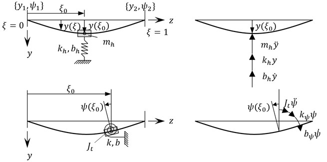
Below, it is assumed that the forces from the bearings operate pointwise (Fig. 4). In contrast to the bearing model described in Section 4, in a simplified model it is necessary to interlock transverse movements of the movable part of the bearing and the housing.
Displacements of beams ends representing the section of the shaft are already established, because they are known movements of the inertial elements with which the shaft is rigidly coupled. Euler angles ψ, θ, φ need to be transformed into the global system in order to calculate the angles of deflection and rotation ϑx, ϑy, ϑz of a beam. In the case of small enough ψ, θ it can be shown that the angles ϑx, ϑy, ϑz are approximately equal angles ψ, θ, φ [11].
The idea of a simplified model is explained for displacements associated with bending in the plane yz. Nodal displacements of a beam element can be written as a vector qe=[y1-ψ1y2-ψ2]T. On the basis of the nodal displacements can be calculated displacements and then velocity and acceleration of any point within an element:
where: Nij – shape functions of a beam, ξ dimensionless value from the scope 〈0,1〉. Eq. (9) can be rewritten in a form: q=Nqe and then calculate ˙q(ξ)=N˙qe.
The impact of the bearing in a yz plane can be replaced by distributed loads in a form (occur relationships: ξ=z/L and δ(z)=dH/dz, δ(z)=δ(ξ)/L):
where mh – mass of bearing housing; bh, kh – damping and stiffness of base; Jt moment of inertia of bearing, bψ, kψ – damping and stiffness of bearing, δ(ξ) – Dirac delta, H(ξ) – Heaviside function.
Fig. 4Sketch for the calculation of additional nodal forces caused by the bearing
Distributed inter nodal loads trigger additional forces focused in nodes of beam element Q=Kqe+Q0, where K is stiffness matrix in plane yz. These additional forces can be calculated by comparing the work prepared:
because: δq=Nδqe, z=Lξ, dz=Ldξ.
Distributed load Eq. (10) can be expressed by shape functions and nodal values:
Since the integral on the right side of Eq. (11) is equal to the value of the integrand at the point ξ0 is:
-NT(ξ0)[kh00kψ]N(ξ0)qe.
The matrix product of shape functions forms a symmetrical 4x4 matrices in a form of:
which can be calculated once at the beginning of the simulation based on the input defining the position of center of bearing with respect to the element. Finally, additional nodal forces can be calculated from the formula:
In a similar manner shall be calculated forces in a plane xz. There is also a possibility to take into account the friction forces. If the mass of the bearing housing is omitted, the case when the bearing acts on a longer section of the shaft as elastic foundation can be generalized as shown. It is then to modify the Eq. (10) for the distributed loads.
6. Numerical example
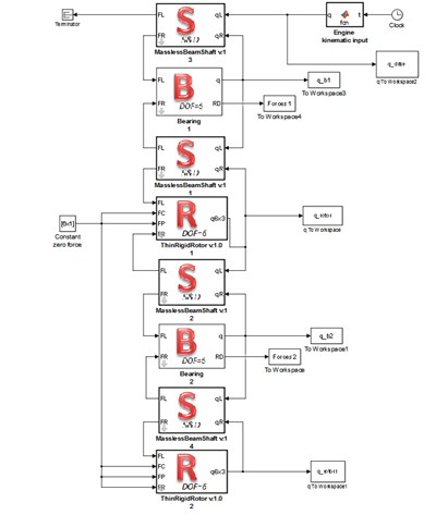
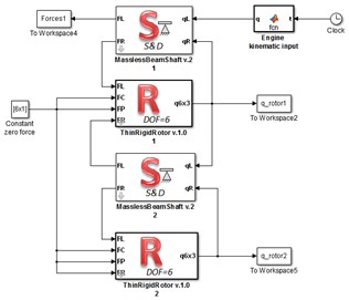
The Fig. 5 shows two dynamic models of an exemplary rotating system made in Simulink, using author’s library previously mentioned. The rotating system consists of two rigid rotors mounted on a shaft supported on two bearings. Both described dynamic models of bearings was used. Similarly, as shown in Fig. 1, rotor 1 has a greater mass, static and dynamic unbalance and is positioned centrally between the bearings. Rotor 2 is located at the end of the shaft near the bearing. In time of 2.5 s the start-up of the rotating machine and then motion with a constant speed 1000 rad/s was simulated.
Fig. 5Simulink models of an exemplary rotating system
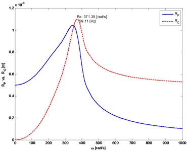
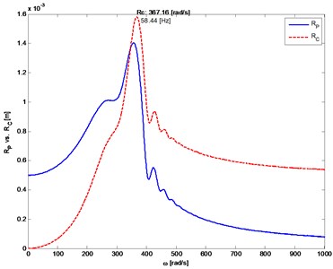
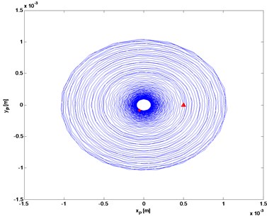
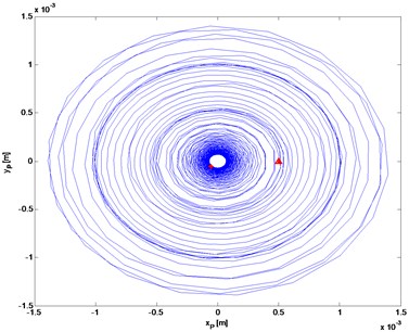
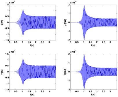
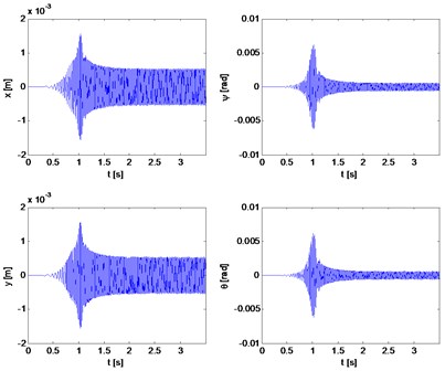
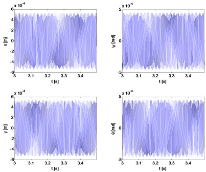
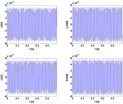
Figs. 6 to 11 show selected examples of the simulation results obtained with the use of the both bearings models: a) model described as first and b) the simplified model. Despite the use in models identical parameters of stiffness and damping, during passage through the critical states, the amplitudes of transverse and torsional vibrations are higher for the simplified bearing model. Simultaneously the rotor speeds at which the transverse vibration amplitude is the largest (critical speeds) are close to each other. However, consistency of results is very good in range of subcritical and supercritical speeds (Fig. 11). One should also emphasize that the in case of simplified model the simulation time was close to 50 % shorter.
Fig. 6The distance from the axis of rotation of the mass center (P) and the geometric center (C) of the rotor 1 depending on rotor’s angular velocity
a)
b)
Fig. 7The trajectory of rotor 1 center of mass (self-centering)
a)
b)
Fig. 8Transverse and gyroscopic vibrations of rotor 1
a)
b)
Fig. 9Torsional vibration velocity (rotor 1)
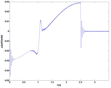
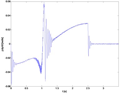
Fig. 10The distance from the axis of rotation of the mass (P) and the geometric center (C) of the rotor 2
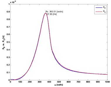
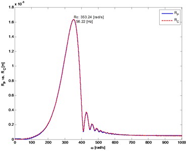
Fig. 11Transverse and gyroscopic vibrations of rotor 1 during movement of the fixed speed
7. Conclusions
Performed simulations showed that the modeling of bearings in rotating systems has a significant impact on the obtained results. The proposed simplified model of the bearing, in which the action of the bearing is replaced with statically equivalent concentrated forces, proved to be a low accurate when the system passes through the critical states. Despite the differences in amplitude, similar values of critical speeds were determined. Because the model with simplified bearings is almost 50 % faster, it can be used in the future for rough evaluation of basic parameters of the rotating system and, for example, in the case of pre-selection of the parameters of vibration dampers.
References
-
Vance J., Zeidan F., Murphy B. Machinery Vibration and Rotordynamics. John Wiley and Sons, New Jersey, 2010.
-
Burdzik R., Węgrzyn T., Konieczny Ł., Lisiecki A. Research on influence of fatigue metal damage of the inner race of bearing on vibration in different frequencies. Archives of Metallurgy and Materials, Vol. 59, Issue 4, 2014, p. 1281-1287.
-
Burdzik R. Implementation of multidimensional identification of signal characteristics in the analysis of vibration properties of an automotive vehicle’s floor panel. Eksploatacja i Niezawodność – Maintenance and Reliability, Vol. 16, Issue 3, 2014, p. 439-445.
-
Tadina M., Boltezar M. Improved model of a ball bearing for the simulation of vibration signals due to faults during run-up. Journal of Sound and Vibration, Vol. 300, Issue 17, 2011, p. 4287-4301.
-
Sopanen J., Mikkola A. Dynamic model of a deep-groove ball bearing including localized and distributed defects. Part 1: theory. Proceedings of the Institution of Mechanical Engineers, Part K: Journal of Multi-body Dynamics, Vol. 217, Issue 3, 2003, p. 201-211.
-
Lim T. C., Singh R. Vibration transmission through rolling element bearings, part 1: bearing stiffness formulation. Journal of Sound and Vibration, Vol. 139, Issue 2, 1990, p. 179-199.
-
Wensing J. A. On the Dynamics of Ball Bearings. Ph.D. Thesis. University of Twente, Enschede, The Netherlands, 1998.
-
Kiciński J. Rotor Dynamics. Print IMP PAN. Instytut Technologii Eksploatacji in Gdańsk, Radom. 2006.
-
MESYS Rolling Bearing Calculation Software. MESYS AG, Zurich.
-
Tiwari R., Chakravarthy V. Simultaneous identification of residual unbalances and bearing dynamic parameters from impulse responses of rotor-bearing systems. Mechanical Systems and Signal Processing, Vol. 20, Issue 7, 2006, p. 1590-1614.
-
Matyja T., Łazarz B. Modeling the coupled flexural and torsional vibrations in rotating machines in transient states. Journal of Vibroengineering, Vol. 16, Issue 4, 2014, p. 1911-1924.
-
Matyja T. Model of stiff rotor with six degrees of freedom. 20th International Congress on Sound and Vibration, Bangkok, Thailand, 2013.
-
Matyja T. The proposal of methodology for modeling coupled flexural-torsional vibrations in transient states of rotating systems. PIB, Radom, 2014, (in Polish).
