Abstract
In this study, we investigate the influence of the location of the counterweight on the flutter characteristics of an all-moving fin. The modal characteristics of the fin are obtained via the finite element method and sensitivity analysis. The supersonic unsteady aerodynamic loads are calculated by local piston theory. The flutter motion equations based on the modal coordinates are established by applying the Lagrange equation. The flutter boundary with respect to the mode characteristics, especially the nodal lines of the mode shapes, has been studied. The results show that different counterweight locations can result in different flutter boundaries. When the counterweight is located at the intersection of the leading edge and tip chord, the increase in the critical dynamic pressure is most obvious. In engineering design, the flutter suppression of an all-moving fin cannot be guided simply by the forward movement of the mass centroid or an increase in the frequency ratio of torsion relative to bending. When the counterweight is added around the leading edge of the root chord to move the mass centroid forward, the critical dynamic pressure can even decrease. The counterweight suppresses the flutter by weakening the coupling of different mode shapes. Thus, the counterweight should be placed at the location where the degree of bending-torsion coupling is reduced.
1. Introduction
Flutter is a common aeroelastic instability phenomenon. Flutter always results in the failure of flight, so it is an important engineering requirement and thus preventing, alleviating, or suppressing flutter is an active research topic. Active flutter suppression technology has developed rapidly in recent years, but few studies have applied active flutter suppression to actual complex vehicles compared with the vast number of studies that have applied this technology to simplified models or verification tests in wind tunnels. Livne [1] noted that the safety and cost of applying active control technology in actual airplanes and wind tunnel models to represent the complexity of real airplanes might be the main explanations for this discrepancy. In fact, rational changes in the mass and stiffness distribution are used widely to prevent and suppress flutter in actual vehicles at the design stage. Active control has only been used to prevent flutter in cases where changes in the mass and stiffness are either not effective and/or not practical [2, 3].
Mass balance has been employed most widely to prevent flutter from occurring at the fin, rudder, and control surface. This principle was introduced in many classical studies of aeroelasticity based on research using typical section models [4, 5]. The frequency ratio and mass centroid can be changed by adding a counterweight, so the flutter boundary characteristics with respect to these parameters can be discussed and summarized.
The aforementioned studies were performed in the context of a typical section, but in practice, it is not easy to achieve complete control in real vehicles. For example, a low aspect radio sweptback control fin has been used primarily in supersonic missiles and rockets. The mass centroid of this type of fin is always backward, especially in a highly sweptback fin. It is difficult to move the mass centroid forward sufficiently for this type of fin to achieve a large increase in the flutter boundary. One reason for this difficulty is that mass overbalance can occur when adding a counterweight to the fin, which results in excess weight in terms of mass and rotary inertia, and thus more load on the actuator.
To determine the structure modes, the finite element method (FEM) and ground vibration test are indispensable procedures during vehicle design. Thus, in real vehicle design, flutter analysis based on a truncated set of structure modes is used widely. However, the mode shapes of real flexible vehicles are more complex than those of typical section models. Obviously, the flutter characteristics are related to the mode shapes, but few studies have considered how the flutter boundary varies with the nodal lines of the mode shape.
The two main objectives of this study are as follows.
1) To investigate the influence of counterweight redistribution on the modal and flutter characteristics of an all-moving fin as a reference for real vehicle design.
2) To discuss and summarize the rule of bending-torsion at the flutter boundary with respect to the mode characteristics, especially the nodal lines of the mode shapes.
In the present study, the modal characteristics with respect to counterweight locations using FEM or sensitivity analysis are calculated. The supersonic unsteady aerodynamic loads are calculated using local piston theory. Flutter reanalysis based on the first two modes of the fin with different counterweight locations are also performed. The relationship between the critical flutter dynamic pressure and counterweight locations is discussed in terms of their frequencies and changes in the mode shape. This discussion is very useful for determining the location of a lighter counterweight, but with a large increase in the flutter dynamic pressure to prevent flutter occurring during the design stage for a real fin.
2. Analysis of normal modes
The normal modes of a real fin with a counterweight at different locations can be reanalyzed by Nastran. This process can also be performed more efficiently using sensitivity analysis provided that the changes in the mass and stiffness matrix due to the counterweight are not excessively large. The first order sensitivities of the eigenvalues and eigenvectors to the variable are [6]:
where λ is an eigenvalue, Φ is an eigenvector (orthonormal mode), θ is the variable, and K0 and M0 are the stiffness and mass matrices, respectively.
3. Unsteady aerodynamic loads and flutter analysis
In this study, unsteady pressure distributions are computed using computational fluid dynamics(CFD)-based local piston theory [7]. This method has been applied to the supersonic unsteady pressure computation of two-dimensional airfoils, three-dimensional rudders, and more complex wing–fuselage vehicles [7, 8].
The local flow of the fin is first calculated using an Euler method and the piston theory is then applied locally at each point on the surface with the downwash caused by the deviation of the moving surface relative to its mean location. Local piston theory is described by the following:
where Δp is the unsteady pressure; ρl, al, and W are the local fluid density, the speed of sound, and the downwash speed, respectively, caused by surface deformation Vlδn and vibration Vbn; and n0 and n are the outward normal unit vectors before and after deformation, respectively.
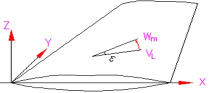
Considering the fin profile characteristics (Fig. 1), the unsteady pressure expression for the fin is given as:
where ±μw(x,y) indicates that μw(x,y) is added for the upper surface and subtracted for the lower surface; μw(x,y) is the direction cosine between the outward normal unit vector and z axis; VxL and VyL are the local flow velocity components parallel to the x and y axes, respectively, which are obtained from a steady flow solution using the CFD method.
Fig. 1Fin coordinates
Neglecting the structural damping, the flutter model is expressed by:
where M, K, and ξ are the generalized mass matrix, generalized stiffness matrix, and generalized coordinates, respectively, and Q is the generalized force vector:
where and are the aerodynamic damping and stiffness matrices, respectively.
By defining the state vector , the flutter equations in state space form are:
where , , and are the dynamic pressure, sonic speed, and Mach number, respectively. The flutter characteristics can be predicted by analyzing the eigenvalue root loci of matrix with increasing dynamic pressure.
4. Application case and discussion
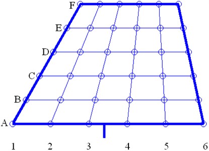
In order to study the influence of the counterweight on the flutter and modal characteristics, we consider a sweptback trapezoidal control fin, as shown in Fig. 2. The fin is divided uniformly into six strips (A → F) from the root chord to the tip chord along the span direction. Six points (1 → 6) are distributed uniformly from the leading edge to the trailing edge of every strip. Thus, there are 36 points, which support the lumped mass of 5 wt. % of the total weight of the fin to simulate the counterweight.
Fig. 2Locations of the counterweight
First, the fin modal without a counterweight is calculated by Nastran. A finite element model consists of 342 nodes and 300 shell elements is built using Nastran (Fig. 3). The actuator stiffness is simplified and represented by bending spring and torsion spring . Fig. 4 shows the first two modes for the fin without a counterweight, which are the bending and torsion modes. The other 36 sets of fin modals with counterweights are obtained by sensitivity analysis. The parameters of the first two modes for the 37 sets of control surface modals are used as the inputs for the flutter analysis.
Fig. 3Finite element model
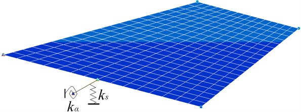
Fig. 4First two modes without a counterweight
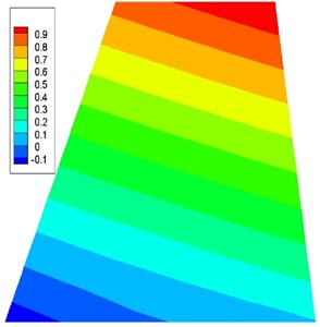
a) 133.15 Hz, bending
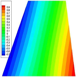
b) 253.01 Hz, torsion
The flutter boundaries are then calculated under the state where 3, 0.3362 kg/m3, and the angle of attack 0°. A finite volume-based unstructured Euler solver is used for the computation of air flow around the fin. Spatial discretization is accomplished by cell-centered finite volume formulation using a AUSM + up scheme. A second-order accurate, full implicit scheme is used to integrate the equations in time domain and a fourth Runge-Kutta time marching method is used in the pseudo time step. Details of aerodynamic mesh are shown in Fig. 5, consisting of 24,616 nodes and 94,950 tetrahedron elements. Pressure distribution is shown in Fig. 6.
Fig. 5Partial view of the CFD surface grid for the fin and the symmetry plane
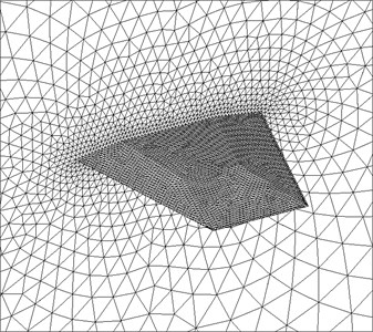
Fig. 6Pressure distribution
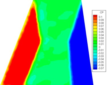
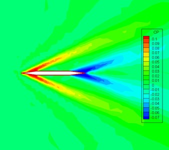
Fig. 7Complex eigenvalues versus the dynamic pressure without a counterweight
a) Real part
b) Imaginary part
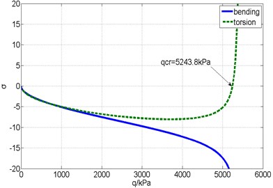
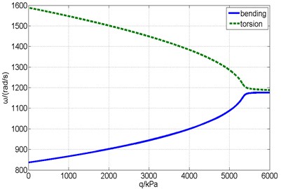
Fig. 7 shows the real and imaginary parts of the complex eigenvalues versus the dynamic pressure obtained from the flutter analysis of the fin without a counterweight. The flutter critical dynamic pressure is 5243.8 kPa, so the flutter modality is bending-torsional coupling. Fig. 8 shows the responses of the structural mode coordinates computed by time domain simulation method at different dynamic pressures ( 0.99, , 1.01).
Fig. 8Responses of the structural mode coordinates

a) 5191.3 kPa

b) 5243.8 kPa

c) 5296.2 kPa
The flutter critical dynamic pressures in the absence and presence of a counterweight are denoted as and , respectively. The dimensionless parameter can be defined as . The critical dynamic pressures of the fin modals corresponding to different counterweight locations are shown in Fig. 9, which is presented in the form of a cloud image. The black line in the image denotes the counterweight locations corresponding to 1. This line indicates that the critical dynamic pressure of the fin cannot be changed by adding a counterweight on this line. The critical dynamic pressure of the fin increases (region of a) or decreases (regions of b and c), respectively, on either side of the black line with a counterweight. In particular, the increase in the critical dynamic pressure is most obvious when the counterweight is added at the intersection of the leading edge and tip chord (F1), which can reach 61 %. When the counterweight is added at the ends of the root chord, the critical dynamic pressures are both decreased, i.e., 23 % and 25 % at the intersection of the root chord and leading edge (A1), and the root chord and trailing edge (A6), respectively.
The variable critical dynamic pressures obtained when the counterweight is added to regions a and c are consistent with the rule of the movement of a mass centroid forward or backward, thereby leading to increases or decreases on the flutter boundary, which allows the study of typical section models. Region b is located around the leading edge of the root chord, so the mass centroid can move forward with the counterweight, but the critical dynamic pressure decreases rather than increases. Thus, it is obvious that the sweptback all-moving fin is not completely consistent with these rules. In engineering design, if the mass centroid is moved forward aimlessly by adding a counterweight to the leading edge, the flutter boundary might not increase, or it could even decrease.
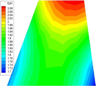
The counterweight also affects the flutter boundary by changing the structure mode. The different counterweight locations result in different variations in each mode frequency. The frequency ratios of torsion relative to bending corresponding to different counterweight locations are shown in Fig. 10, which are presented in the form of a cloud image. When the counterweight is added around the leading and trailing edge of the root chord, reaches the minimum, and the degree of bending and torsional modal coupling is highest. Therefore, the critical dynamic pressures corresponding to regions b and c in Fig. 9 decrease. When the counterweight is added around the tip chord, reaches the maximum, and the critical dynamic pressures corresponding to region a in Fig. 9 increase. However, when the counterweight is located at the leading edge of the tip chord, the critical dynamic pressure is obviously higher than that at the trailing edge, which is not completely consistent with the rule that an increase in the frequency ratio of torsion relative to bending can increase the flutter boundary.
Fig. 9Dynamic pressure versus counterweight location
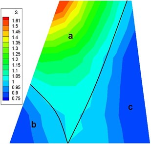
Fig. 10f2/f1 versus counterweight location
From the previous discussion, we may conclude that it is insufficient to explain the change in the rules for the flutter boundary based on the movement of the mass centroid and the variations in the frequency ratios in the first two modes caused by the counterweight. Thus, we consider the rule of bending-torsion at the flutter boundary with respect to the nodal lines of the mode shape.
The flutter modality of the all-moving fin is bending-torsion flutter. The first two natural modes are closer to the pure bending and pure torsion condition, and the degrees of bending and torsion coupling are smaller. Thus, a higher dynamic pressure is needed for the coupling of the two modes. The coupling between the bending and torsion modes of the fin can be determined by analyzing the positions of the nodal lines of the two modes. Fig. 11 shows the variations in the bending and torsion modes without and with the counterweight moving along the tip chord and leading edge. As the counterweight moves from the leading edge to the trailing edge along the tip chord (F1 → F6), the nodal lines of bending and torsion all rotate clockwise using the rudderpost as the pivot. The nodal lines of the bending and torsion modes without the counterweight are located between the nodal lines with the counterweight, i.e., between F1 and F6. From the perspective of the mode shape, when the counterweight is added to the intersection of the tip chord and leading edge (F1), the mode shape is closer to the pure bending and torsion condition, and the degree of bending and torsion coupling is weakest. As the counterweight moves gradually to the trailing edge, the degree of bending and torsion coupling is strengthened gradually. When the counterweight moves to the intersection of the tip chord and trailing edge (F6), the degree of bending and torsion coupling is highest. Therefore, as the counterweight moves from F1 to F6, the critical dynamic pressure is decreased gradually. Moreover, the critical dynamic pressures with the counterweight at the leading edge and trailing edge are higher and lower, respectively, than that without the counterweight. Similarly, as the counterweight moves along the leading edge (A1 → F1), the rules governing the change in the critical dynamic pressure can also be analyzed. It can be seen that the changes in the rules governing critical dynamic pressure can be explained sufficiently by analyzing the influence of the counterweight’s location on the mode shape. The counterweight should be placed at the location where the degree of bending-torsion coupling is reduced.
Fig. 11Nodal lines versus counterweight location
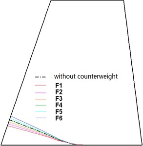
a) Bending mode (counterweight at tip chord)
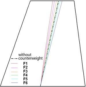
b) Torsion mode (counterweight at tip chord)
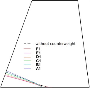
c) Bending mode (counterweight at leading edge)
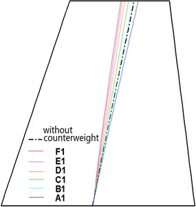
d) Torsion mode (counterweight at leading edge)
5. Conclusions
After analyzing the flutter of a sweptback trapezoidal all-moving fin with different counterweight locations, we give the following useful conclusions related to the design of real vehicles.
1) Different counterweight locations have variable effects on increases or decreases in the critical dynamic pressure. The most obvious effect occurs when the counterweight is located at the intersection of the leading edge and tip chord. The critical dynamic pressure can increase by 61 % when the added counterweight is 5 % of the total weight. When the counterweight is added at the intersections of the root chord and the leading or trailing edges, the critical dynamic pressures decrease by 23 % and 25 %, respectively.
2) It is not possible to ensure that the forward movement of the mass centroid and the increase in the frequency ratio of torsion relative to bending can always increase the critical dynamic pressure. Indeed, when the counterweight is added around the leading edge of root chord, the critical dynamic pressure can even decrease.
3) In engineering design, it is useful to analyze the variety of the nodal lines of mode shapes with different counterweight locations. The counterweight should be placed at the location where the degree of bending-torsion coupling is reduced.
References
-
Livne E. Future of airplane aeroelasticity. Journal of Aircraft, Vol. 40, Issue 6, 2003, p. 1066-1092.
-
Liu D. D., Sarhaddi D., Piolenc F. M. Flutter Prevention Handbook a Preliminary Collection Part A: Flutter Model Design and Ground Vibration Testing. NASA/TP-2006-212490/VOL2/PART2, 2006.
-
Liu D. D., Sarhaddi D., Piolenc F. M. Flutter Prevention Handbook a Preliminary Collection Part B: Aerodynamic and Mass Balance Effects on Control Surface Flutter. NASA/TP-2006-212490/VOL2/PART2, 2006.
-
Dowell E. H., Clark R., Cox D. A Modern Course in Aeroelasticity. 4th Ed., Kluwer Academic, Norwell, MA, 2004.
-
Hodges D. H., Pierce G. A. Introduction to Structural Dynamics and Aeroelasticity. Cambridge University Press, 2004.
-
Fox R. L., Kapoor M. P. Rates change of eigenvalues and eigenvectors. AIAA Journal, Vol. 6, Issue 2, 1968, p. 2426-2429.
-
Zhang W., Ye Z., Zhang C., Liu F. Supersonic flutter analysis based on a local piston theory. AIAA Journal, Vol. 47, Issue 10, 2009, p. 2321-2328.
-
Shi X., Tang G., Yang B., Li H. Supersonic flutter analysis of vehicles at incidence based on local piston theory. Journal of Aircraft, Vol. 49, Issue 1, 2012, p. 333-337.
About this article
This work was sponsored by Shanghai Rising-Star Program (14QB1402400).
