Abstract
This paper presents a hydraulic actuator and tendon drive system that was specifically designed for a lower-limb exoskeleton to provide high power and low inertia. The dynamics of the actuator-tendon system were analyzed based on the exoskeleton system and an adaptive sliding-mode trajectory tracking controller was designed for the drive system. The stability proof indicates that the controller is globally stable. The experimental results demonstrated that the controller provides high tracking accuracy and is robust to external disturbances and unmodeled nonlinearities. Moreover, the controller has less errors than the conventional PID controller. Further tests that included the joints of the exoskeleton were conducted to verify the performance of the controller.
1. Introduction
An exoskeleton is a wearable mechatronic device that provides improved functionality to the human body for various tasks, such as rehabilitation therapy, enabling individuals to carry heavy loads, and assisting the disabled and the elderly. These devices allow the wearer to perform certain tasks in daily life with less fatigue [1]. Currently, many researchers throughout the world are investigating exoskeletons. Exoskeleton research involves many aspects, including biomechanics, sensors, drive technology, and control [2]. The drive system of an exoskeleton, which includes motors and hydraulic or pneumatic actuators, is very important. Together, the drive system and the control system determine the performance of the exoskeleton and must be able to provide sufficient power. The hydraulic systems have higher ratios of force or torque to weight or size than electric systems. Thus, a hydraulic drive system is preferable for exoskeletons, which require high power. Such systems were used in the BLEEX [3] (Berkeley Lower Extremity Exoskeleton) and the XOS exoskeleton [4, 5]. Use of a hydraulic rather than electric drive system provides more power and decreases the joint inertia; both of these properties are desirable for providing assistance with walking. To obtain these desired properties, hydraulic actuators are installed on the back of exoskeleton, and tendons are installed on the front to connect the hydraulic actuators and the joints, thereby providing a lightweight and flexible transmission path.
One disadvantage of hydraulic systems is that they may leak hydraulic fluid, which is detrimental to the environment [6]. Additional challenges to precision control include nonlinearities that can arise from a loss of hydraulic fluid, changes in the effective bulk modulus of the hydraulic fluid with temperature, friction and other uncertainties. When designing a controller, we must consider the influence of uncertainties, external disturbances and other nonlinearities to achieve the desired tracking performance.
Conventional PID control techniques can provide good performance for hydraulic servo systems under nominal conditions, but the performance degrades when the operating conditions change because of external loads or disturbances. Some various advanced methods, including intelligent control methods, have been developed to solve this problem. An adaptive robust motion control algorithm was employed by Yao to improve the performance of hydraulic systems with double-rod hydraulic actuators in the presence of parameter uncertainties and nonlinearities [7, 8]. Yao also developed an adaptive robust controller for single-rod hydraulic actuators [9]. Similarly, variable-structure control, which is also known as sliding mode control, has been used for hydraulic systems [10, 11]. An improvement of the variable-structure control method is adaptive sliding mode control, which has been applied to an electro-hydraulic servo system with a double-rod actuator [12]. These control algorithms are robust to uncertainties and nonlinearities and exhibit better performance than standard control systems.
The use of tendons for position transmission complicates the control of the system. We therefore studied the tendon characteristics to eliminate the adverse effects and obtain the desired control performance. In addition, the nonlinearities in the hydraulic system were accounted for to ensure precise tracking of the exoskeleton joints.
In this paper, a power-assisting exoskeleton for carrying loads was developed, the dynamics of the hydraulic actuator and tendon position transmission system were analyzed based on the exoskeleton and an adaptive sliding mode trajectory tracking controller for a hydraulic actuator and tendon servo system of an exoskeleton is proposed. The stability of the controller is proved analytically. The controller can guarantee joint tracking performance and is robust with respect to uncertain external disturbances. Furthermore, the controller can achieve the desired results using a one-DOF (degree of freedom) hydraulic cylinder and joints control in the exoskeleton. The tracking performance is demonstrated through experiments.
This paper is organized as follows. Section 2 introduces the exoskeleton that we developed. The dynamics of the hydraulic control system are described in Section 3, and the tendon model is presented in Section 4. The adaptive sliding mode control algorithm and the stability analysis are presented in Section 5, and the tracking performance of the system with the proposed controller is demonstrated in Section 6. Our conclusions are presented in Section 7.
2. Background
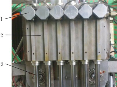
We developed a power-assisting exoskeleton for carrying loads; a diagram and a photograph of the system are shown in Fig. 1. Any healthy person between 165 and 185 cm in height can carry loads and walk easily wearing this exoskeleton. Fig. 1(a) shows a diagram of the exoskeleton system, and Fig. 1(b) shows a working prototype, which includes hip, knee and ankle joints. This exoskeleton has six degrees of freedom, which are shown in Fig. 2. Separate hydraulic actuators and tendons drive each joint. An integrated set of hydraulic cylinders was specifically designed for the exoskeleton and is shown in Fig. 3. The proximal end of tendon connects each rod of the cylinder and the distal end of tendon is fixed on the joint. The tendon can move freely in the sheath. The tendon is pulled by the hydraulic cylinder to produce the flexion and the extension in sagittal plane.
Fig. 1Exoskeleton: 1 – tendon, 2 – tension sensor, 3– attitude sensor, 4 – hydraulic actuator mounting panel, 5 – back panel, 6 – waist panel, 7 – hip joint, 8 – spring, 9 – knee joint, 10 – ankle joint
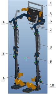
a) Ilustration of the exoskeleton
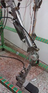
b) Prototype of the exoskeleton
Fig. 2Exoskeleton degrees of freedom
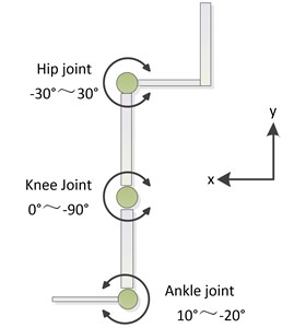
Fig. 3Integrated hydraulic cylinder set: 1 – electro-hydraulic servo valve, 2 – cylinder, 3 – piston rod
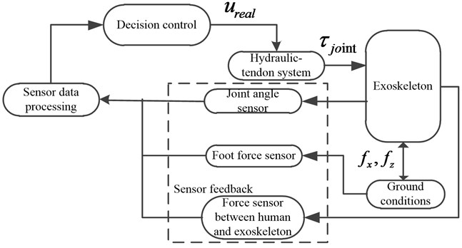
The architecture of the exoskeleton control system is shown in Fig. 4. The main components include the controller, sensors, data acquisition and processing system. The function of the sensor data acquisition system is to measure the state of the exoskeleton in real time using foot force sensors, joint angle sensors, and force sensors that are installed between the user and the exoskeleton and detect the intended motion of the user. Based on the sensor data, the controller generates commands to move the joints through the actuator-tendon drive system. The primary purpose of the controller is to coordinate each joint of the exoskeleton and enable the exoskeleton to follow the motion of the operator in real time. To ensure that the operator can walk comfortably while wearing the exoskeleton, it is very important that the control system moves the joints to follow the desired trajectory precisely.
Fig. 4Control system architecture of the exoskeleton
3. Dynamics of the hydraulic system
In this section, we present the dynamics of the hydraulic actuator which is the first step of the controller design process. The dynamics of the hydraulic actuator were presented previously [13]; thus, we present the state equation without details.
The displacement, velocity and acceleration of the actuator piston were chosen as the state variables, which are represented as x=[x1,x2,x3]T≜ were the displacement, velocity and acceleration of the actuator piston, respectively. The state equation can be expressed as follows:
where:
where:
is the discharge coefficient, is the servo spool valve displacement, is the servo spool valve area gradient, is the effective bulk modulus, is the spring stiffness coefficient, is an external disturbance force, and are cylinder chamber flows, is the supply pressure of the hydraulic fluid, and are the pressures of the working chambers, is the fluid density, is the load mass, is the viscous damping coefficient, and are the piston areas, is the total leakage coefficient, is the control input, is the displacement of the piston, and are the cylinder chamber volumes.
The state Eq. (1) is nonlinear. It is difficult to obtain accurate values for several of the parameters in this equation, such as m, , , and . Moreover, certain parameters, such as and are nonlinear and change with the hydraulic oil temperature. These uncertain or time-varying parameters may cause system nonlinearities that make it difficult to design a controller to track a desired trajectory.
4. Tendon model
The third author Chen presented the tendon model in a previous paper [14, 15]; thus, the position transmission model is presented here without a discussion of its development. The displacement of the distal end of a tendon at a joint is expressed as:
where:
imply the tendon stationary and imply that the tendon is moving. is the displacement of the tendon.
Where:
is the curvature at position , is the friction coefficient, is the time, is the length of the sheath, and are the elastic modulus and cross-sectional area of the tendon, respectively.
The transmission inverse model of the tendon can be easily obtained from Eq. (4) and is expressed as:
where, is the desired input and is the inverse output.
We can obtain the output trajectory for the actuator using the preceding equation and the desired tendon output trajectory.
5. Adaptive controller design
The control objective is to design a control law to enable to track the desired trajectory as closely as possible.
In the following, to simplify the notation, denotes the th component of the vector .
We make the following assumptions:
Assumption 1. The derivative of , which represents external disturbances, is bounded, and the following inequality is always satisfied:
where is a known positive constant.
Assumption 2. The desired trajectory is continuous and known. Furthermore, , where is a compact set [16].
With these assumptions, and the uncertain variables in the state-space equation are linearly parameterized [9], Eq. (1) can be simplified as follows:
where:
Because , , , are uncertain parameters, , , , and ( 1,…, 4) are also uncertain.
Fact 1., , and are bounded and always satisfy the following inequalities:
where , , , and are known positive constants.
Fact 2. , , , , and are positive; thus, is positive. Because , , the inequalities and are easily obtained. Thus:
The sliding hyperplane is defined as follows [17]:
where , , , and and satisfy the Hurwitz stability criterion [18]. Differentiating Eq. (13), the following equation is obtained:
where represents the estimate of (1, 2), and is the estimate of (1,…, 10). The errors in the estimates are as follows:
In general, sliding mode control consists of an equivalent control and a switching control [19-21]. The equivalent and switching control terms are combined, and the actual values of the parameters are substituted with the estimated values. The control law is expressed as follows:
where is a positive constant that satisfies:
A Lyapunov function is selected as follows:
where, (1,…, 12) are positive constants.
The time derivative of the Lyapunov function is:
Substituting Eq. (16) into Eq. (19), the following equation is obtained:
The following adaption laws are chosen:
where the constants (1,…, 12) determine the adaptation rates of each uncertain parameter.
Eq. (20) is transformed into:
From Eq. (17), we can obtain the following inequality:
where, is a positive constant.
By integrating both sides of the inequality in Eq. (23), the following inequality is obtained:
Eq. (24) implies is bounded and the function is uniformly continuous. According to Barbalat’s lemma, as , which guarantees that the system state moves forward and remains on the sliding surface .
The conditions and , i.e., is positive definite and is negative definite, guarantee that the system is globally, uniformly and asymptotically stable.
6. Experimental validation
6.1. Experiment preparation
The acceleration of the piston rod must be known for the feedback signal of the control system. The displacement of the piston can be obtained directly via a linear displacement sensor. We can obtain the velocity by differentiating the displacement signal and filtering the data. However, it is very difficult to obtain accurate values for the acceleration. In order to obtain relatively accurate values for the acceleration, we can evaluate them through the integral chain differentiators. The three-order integral chain differentiator is expressed as follows [22]:
where , , , and , , and satisfy the Hurwitz stability criterion. The variables , , and are the estimates of , , and , respectively.
A first-order low-pass filter is included at the output of the second differentiator to suppress noise.
6.2. Experiment setup
To test the proposed trajectory tracking controller, a hydraulic-actuator and tendon servo system was constructed. The system is composed of an integrated hydraulic station which is used to supply pressure oil, an electro-hydraulic servo valve, a hydraulic cylinder with a single piston rod, a sheath-tendon transmission system, a laser displacement sensor, two pressure sensors manufactured by GE (General Electric corporation), two control computers, and a digital-to-analog (D/A) and analog-to-digital (A/D) module (PCL-812PG) manufactured by Advantech Technology. The PCL-812PG module acquires the piston rod displacement and sends the control signal.
The controller was implemented in the MATLAB® Real-Time Workshop® (RTW) software package using the host/target computer mode. Fig. 5 shows the layout of the actuator-tendon system. The block diagram of the actuator-tendon system in the MATLAB/Simulink® environment is shown in Fig. 6. The host and target computers were connected via an Ethernet network. At the start of an experiment, the control program is compiled on the host computer and then transmitted to the target computer. When program execution is completed, the experimental data are transmitted to the host computer. The servo amplifier transforms the voltage signals to current signals to control the servo valve. The hydraulic valve receives the current signal from the servo amplifier to control the hydraulic oil flow. The displacement of the cylinder is measured by a laser sensor in real time and acquired by the PCL-812PG module.
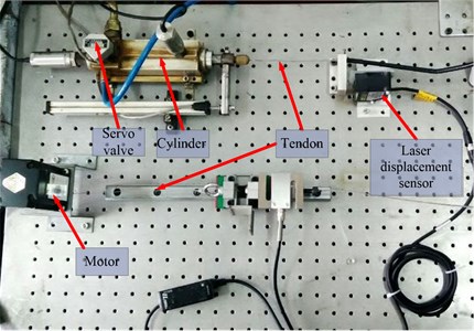
The experiment platform is shown in Fig. 7. A hydraulic cylinder is used to test the proposed controller. The electro-hydraulic servo valve and hydraulic cylinder are installed together. Commands are sent to the alternating-current motor to generate the variable load. One end of the tendon is connected to the hydraulic actuator, and the other end is connected to the motor.
Fig. 5Real-time control schematic
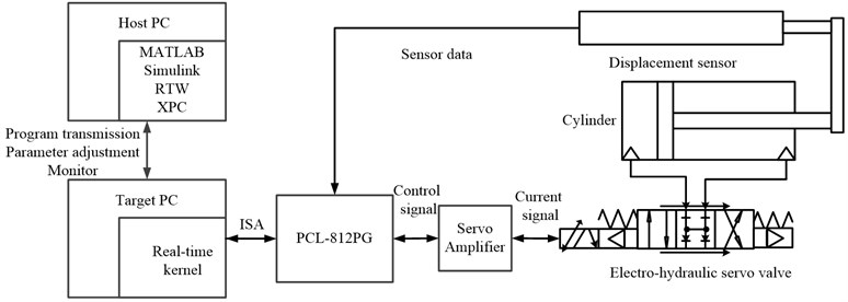
Fig. 6MATLAB/Simulink block diagram of the control system

Fig. 7Experiment platform
6.3. Uncertain parameters
The supply pressure of the hydraulic oil is 5 MPa. The working areas of the cylinders are 4.9×10⁻⁴ m2 and 2.9×10⁻⁴ m2. The stroke of the cylinders is 100 mm. Because the terms , include the control input , the initial values of several of the uncertain parameters must be known. The initial values of these parameters were as follows: 4.5×10⁻⁵ m3, 2 kg, 800 MPa, 850 kg/m3, 5×10-13 m3/Pa, 1.2×10⁻², 0.8, and 1×10⁻³. In the experiments, there was only an inertial load; thus, 0 and 0. The initial values of the coefficients (1,…, 10) were obtained from these parameters.
6.4. Experiment results
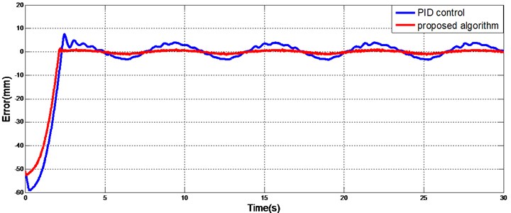
The desired trajectory was chosen to be a sine function. Because of the presence of the tendon, the output trajectory of the actuator must be modified according to the desired trajectory. For comparison, a PID (proportional-integral-derivative) controller was also designed. The values of the PID controller gains were P 2.58, I 0.02, and D 0.5, where P, I, and D are the proportional, integral and derivative gains, respectively. Figs. 8 and 10 show the trajectories for a single actuator with the proposed adaptive sliding mode controller and the PID controller under constant and variable loads, respectively. Fig. 9 and 11 show the tracking errors. The initial displacement of the actuator was -50 mm. The desired trajectory started at 0 mm; thus, the initial error was relatively large. A phase lag was present in the PID-controlled tracking, which made it difficult to achieve accurate tracking. The trajectory yielded by the sliding mode controller coincided with the desired trajectory and had less error after the initial transient than did the PID controller.
Fig. 8Sinusoidal track without a load
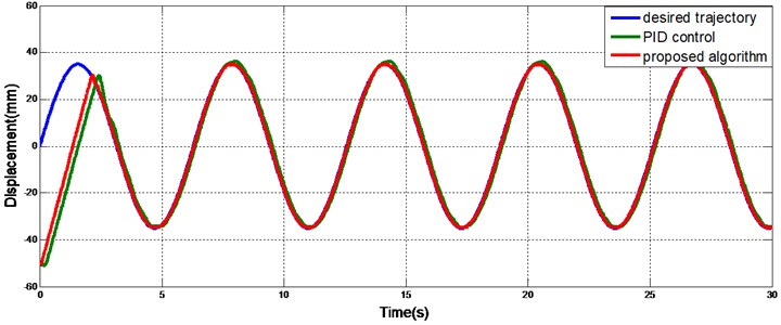
Fig. 9Tracking error without a load
As shown in Fig. 10 and 11, the trajectory produced by the PID controller oscillates and does not closely track the desired trajectory when the load varies with time, but the sliding mode controller is largely unaffected by the variable load and is robust to the external disturbances.
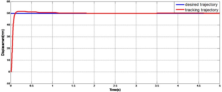
Generally, the step response can examine the performance of one system in harsh conditions. Fig. 12 shows the response of hydraulic actuator with the proposed algorithm. There is a little shoot in step response but the tracking curve is stable at very short time and coincides with the desired trajectory.
The results verify the performance of the proposed control algorithm for a single hydraulic cylinder. However, these results are not sufficient to demonstrate the effectiveness of the controller in the exoskeleton in operation. To further test the effectiveness of proposed control algorithm, tests that included the joints of the exoskeleton were conducted. Angle sensors were installed in the exoskeleton joints to measure the rotation angles of the joints in real time. The desired trajectories were chosen to be sine functions for this test. The first reference trajectory, which is shown in Fig. 13, was . The second reference trajectory, which shown in Fig. 14, was also sinusoidal, but the frequency and the amplitude were not fixed. The trajectory was from 0 to 24 s and subsequently. Regardless of whether the amplitude and frequency of the reference trajectory were fixed or variable, excellent tracking was obtained with the proposed controller.
Fig. 10Sinusoidal tracking with a variable load
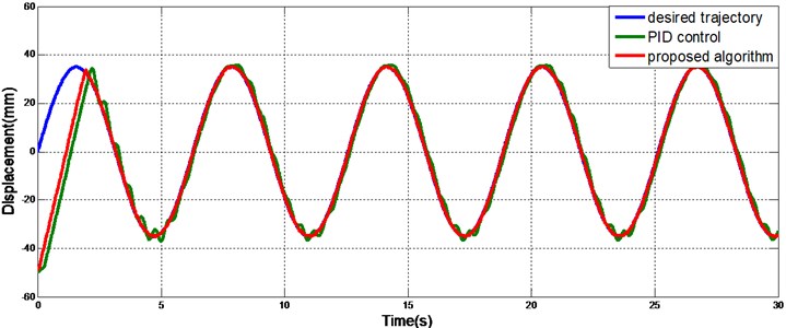
Fig. 11Tracking error with variable load
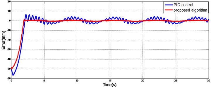
Fig. 12Step response
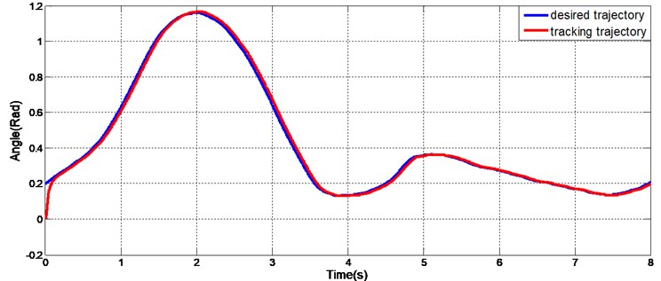
To fully demonstrate the effectiveness of the proposed controller for the exoskeleton, a test of human gait trajectory tracking with the exoskeleton was conducted. The gait trajectory was obtained from a normal individual walking in a gait measurement system. The data were consistent with the CGA (Clinical Gait Analysis) data obtained by other academic institutions. The human gait, including the hip and knee trajectories, was used as the reference trajectory. As shown in Fig. 15 and 16, the tracking in both the hip and knee joints was good. There were slight lags only when the direction of the joint motion changed. However, these lags did not affect the tracking performance of the exoskeleton while walking. These experimental results verify that the proposed controller is effective and significant.
Fig. 13Sinusoidal tracking of exoskeleton joint
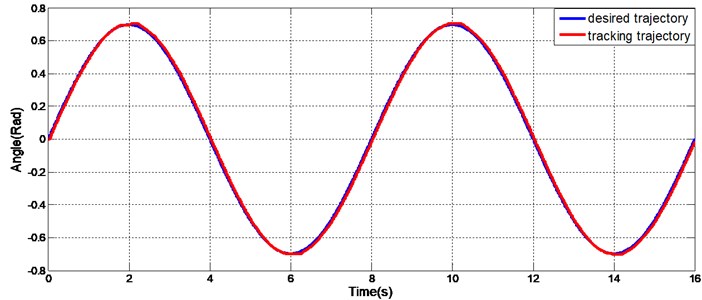
Fig. 14Variable frequency and variable amplitude sinusoidal track of the exoskeleton joint
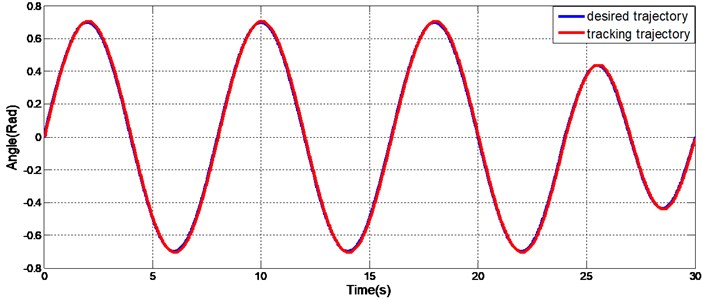
Fig. 15Hip gait trajectory track of the exoskeleton joint
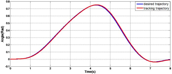
Fig. 16Knee gait trajectory track of the exoskeleton joint
7. Conclusions
In this paper, the details of the exoskeleton, including the mechanical design, degrees of freedom, drive system, transmission system, and control architecture, were presented. An adaptive trajectory tracking controller for the actuator-tendon servo system was developed to compensate for tracking errors in the presence of uncertainties, thereby providing accurate trajectory tracking. It was proved that the system is globally, uniformly, and asymptotically stable. The experimental results verified that the controller is effective and robust with respect to external disturbances. The proposed controller was successfully tested on the exoskeleton system. This research is only preliminary, but it forms the basis for stable exoskeleton walking. The ultimate goal of trajectory tracking is to ensure that the exoskeleton can function with the operator.
References
-
Pons Jose L. Wearable Robots: Biomechatronic Exoskeletons. Wiley, New York, 2008.
-
Mohammed S., Amirat Y., Rifai H. Lower-limb movement assistance through wearable robots: state of the art and challenges. Advanced Robotics, Vol. 26, Issue 1, 2012, p. 1-22.
-
Zoss A., Kazerooni H. Architecture and hydraulics of a lower extremity exoskeleton. International Mechanical Engineering Congress and Exposition, Orlando, Florida, USA, 2005, p. 1447-1455.
-
Jacobsen S. On the development of XOS, a powerful exoskeletal robot. IEEE/RSJ International Conference on Intelligent Robots and Systems, San Diego, CA, 2007.
-
Xie H., Li X., Li W., Li X. The proceeding of the research on human exoskeleton. International Conference on Logistics Engineering, Management and Computer Science, Shenyang, China, 2014, p. 752-756.
-
Ji Min L., Han Me K., Sung Hwan P., Jong Shik K. A position control of electro-hydraulic actuator systems using the adaptive control scheme. Proceedings of the 7th Asian Control Conference, Hong Kong, China, 2009, p. 21-26.
-
Bin Y., Fanping B., George T. C. Chiu Nonlinear adaptive robust control of electro-hydraulic servo systems with discontinuous projections. Proceedings of the 37th IEEE Conference on Decision and Control, Tampa, Florida, USA, 1998, p. 2265-2270.
-
Bin Y., Fanping B., George T. C. Chiu Non-linear adaptive robust control of electro-hydraulic systems driven by double-rod actuators. International Journal of Control, Vol. 74, Issue 8, 2001, p. 761-775.
-
Bin Y., Fanping B., John R., George T. C. Chiu Adaptive robust motion control of single-rod hydraulic actuators: theory and experiments. IEEE/ASME Transactions on Mechatronics, Vol. 5, Issue 1, 2000, p. 79-91.
-
Bonchis A., Corke P. I., Rye D. C., Ha Q. P. Variable structure methods in hydraulic servo systems control. Automatica, Vol. 37, Issue 4, 2001, p. 589-595.
-
Shu W., Richard B., Saeid H. Sliding mode controller and filter applied to an electrohydraulic actuator system. Journal of Dynamic Systems, Measurement, and Control, Vol. 133, Issue 2, 2011, p. 245041-245047.
-
Cheng G., Shanan Z. Adaptive time-varying sliding mode control for hydraulic servo system. International Conference on Control, Automation, Robotics and Vision, Kunming, China, 2004, p. 1774-1779.
-
Lu X., Jia S., Zhou J., Wang X. Adaptive sliding mode position control of electro-hydraulic servo system with single-rod actuators. 11th IEEE International Symposium on Robotic and Sensors Environments, Washington, DC, USA, 2013, p. 220-225.
-
Lin C., Xingsong W. Modeling of the tendon-sheath actuation system. 19th International Conference on Mechatronics and Machine Vision in Practice, Auckland, New-Zealand, 2012, p. 489-494.
-
Lin C., Xingsong W., Weiliang X. Inverse transmission model and compensation control of a single-tendon-sheath actuator. IEEE Transactions on Industrial Electronics, Vol. 61, Issue 3, 2014, p. 1424-1434.
-
Xingsong W., Chunyi S., Hong H. Robust adaptive control of a class of nonlinear systems with unknown dead-zone. Automatica, Vol. 40, Issue 3, 2004, p. 407-413.
-
Yachao Y., ChiCheng C. Robust adaptive trajectory control for an omnidirectional vehicle with parametric uncertainty. Transactions of the Canadian Society for Mechanical Engineering, Vol. 37, Issue 3, 2013, p. 405-413.
-
Richard C. Dorf, Bishop R. H. Modern Control Systems. 12th ed., Prentice Hall, New Jersey, 2010.
-
Utkin V., Guldner J., Shi J. Sliding Mode Control in Electro-Mechanical Systems. Taylor and Francis Group, 2009.
-
Liu J., Wang X. Advanced Sliding Mode Control for Mechanical Systems: Design, Analysis and Matlab Simulation. Tsinghua and Springer Press, Beijing, 2011.
-
Van M., Hee-Jun K., Kyoo-Sik S. Adaptive fuzzy quasi-continuous high-order sliding mode controller for output feedback tracking control of robot manipulators. Proceedings of the Institution of Mechanical Engineers, Part C – Journal of Mechanical Engineering Science, Vol. 228, Issue 1, 2014, p. 90-107.
-
Wang X., Chen Z., Yuan Z. Design and analysis for new discrete tracking-differentiators. Applied Mathematics – A Journal of Chinese Universities, Vol. 18, Issue 2, 2003, p. 214-222.
About this article
This work is supported by National Nature Science Foundation of China (Grant No. 51205182), Nature Science Foundation of Jiangsu Province (Grant No. BK2012474) and Graduate Research Innovation Foundation of Jiangsu Province (Grant Nos. CX10B-063Z, CXZZ_0140).
The first author Lu Xinliang analyzed the dynamics of the actuator-tendon system, designed the adaptive sliding control algorithms and proved the stability. The test of this paper was written by the first author. The control experiments were implemented by the second author Jia Shan. The tendon model and the transmission characteristics were analyzed by the third author Chen Lin. The idea of adaptive sliding control algorithms was presented and the test was revised by the fourth author Wang Xingsong. The mechanical structure and the control architecture of the exoskeleton system were designed by the fifth author Han Yali.
