Abstract
Piecewise non-smooth model of three-degree-of-freedom rolling bearing system with fault in outer Ring is established by the method of the nonlinear theory. The bifurcations and chaos of bearing system is first studied in this paper. The switching matrixes of system are obtained at the switching boundaries, and the period-doubling bifurcation and Neimark-Sacker bifurcation of non-smooth bearing system is analyzed by combining the switching matrixes with the Floquet theory for smooth systems. The numerical method is used to further reveal the bifurcations and chaos of bearing system through establishing the Poincaré mapping on the collision plane. When the rotating frequency is increased to reach the critical bifurcation point, a pair of complex conjugate Floquet multipliers is on the unit circle and others into a unit circle, and the Neimark-Sacker bifurcation appears. When the rotating frequency is decreased to another critical bifurcation point, one of Floquet multipliers of the system equals to -1 and others into a unit circle, and the period-doubling bifurcation appears. With the variation of rotating frequency, the system also experiences the complex dynamical behaviors of Nermark-Sacker bifurcation of period 3 solution and chaos. The study of bifurcation and chaos of the fault bearing system provides reliable basis for the design and fault diagnosis and provides theoretical guidance and technical support for the actual design in the safe and stable operation of large high-speed rotating machinery.
1. Introduction
Bearing is one of the most important part of the rotating machinery and plays a key role for the safe running of equipment. The dynamic characteristics of high-speed rotor system supported by bearings depend largely on bearing properties. Once bearing is broken, it will cause more serious consequences [1-4]. The nonlinear vibration behaviors caused by fault are very complicated, which has significant effect on the design and fault diagnosis of bearing. In order to ensure stable and safe running of rotor system and decrease economic losses and casualties caused by sudden fault in bearings, the nonlinear vibration mechanism and characteristic of bearings with fault need in-depth study.
The present study of dynamical behavior for bearing is mainly concentrated on normal bearing systems. He et al. [5] studied the dynamics of rolling bearing system with gaps under variable load. Zhang et al. [6] investigated the nonlinear dynamic characteristics and stability of rolling bearing system under the influence of non-equilibrium force. Tang et al. [7] obtained the nonlinear bearing force in work situation based on Hertz elastic contact theory and the kinesiology of rolling bearing, and analyzed vibration features of rolling bearing system. Gao et al. [8] established the dynamical equations of the spindle system based on Hertz contact force model and studied mechanism and pathway of the instability. Though these researches acquire some achievements, the appearance of fault is not considered in bearing systems. When a fault occurs in the actual bearing, the interaction between rolling body and inner or outer ring is similar to elastic collision with gaps. Thus the system becomes a non-smooth piecewise linear system. Because the gaps between rolling body and inner or outer ring is very small and this easily results in the instable phenomena of the system, the nonlinear dynamical behavior at the switching plane in bearing systems must be considered to study the mechanism of vibration.
In this paper, the bifurcations and chaos of rolling bearing system with fault in outer ring is studied. The paper is organized as follows. In Section 2, piecewise non-smooth model of rolling bearing system with fault is established by the method of the nonlinear theory. In Section 3.1, the switching matrixes of system are obtained at the switching boundaries to analyze the bifurcation conditions of systems. In Section 3.2 and 3.3, the period-doubling bifurcation and the Neimark-Sacker bifurcation of systems are investigated through the numerical simulations based on theoretical analysis in the Section 3.1. The paper is completed by the conclusions in Section 4.
2. The model of rolling bearing with fault and its motion equation
According to the rolling bearing model with fault in Fig. 1(a), a simplified model of bearing with the fault in outer ring under the condition of single roller is established (see Fig. 1(b)). In the Fig. 1(b), masses M1, M2 and M3 respectively stand for the equivalent mass of inner ring and shaft, the mass of rolling body and the mass of outer ring. Masses M1, M2 and M3 are connected by linear springs with stiffness K1, K2 and K3, and linear viscous dampers C1, C2 and C3, respectively. When fault occurs in outer ring, the spring with stiffness K4 stands for contact state. F1sin(Ω1T) and F2sin(Ω2T) are the equivalent force. Ω1 and Ω2 are the frequency of rotating shaft and cage respectively. D is the fault depth.
Fig. 1The simplified rolling bearing model
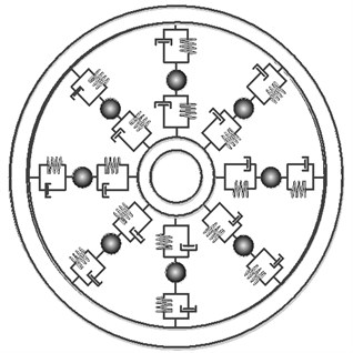
a) Bearing model with fault
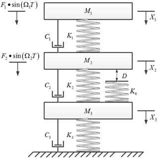
b) The piecewise linear model of bearing with single rolling element
Fig. 2The subspaces of the bearing system
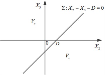
In order to describe the motion process of the bearing system, a switching boundary need be introduced. The boundary function is defined E=X2-X3-D, and then the switching boundary can be expressed as follows:
Thus the state space is divided into two subspaces by the switching boundary Σ, just as shown in Fig. 2.
In Fig. 2, V+={X∈R2|E(X2,X3)>0} stands for contact state of mass M2 and broken spring K4, V-={X∈R2|E(X2,X3)<0} stands for separation state.
According to the above analysis, the dynamical equation is established as follows:
+[K1-K10-K1K1+K2-K20-K2K2+K3][X1X2X3]+H(X)[01-1]=[F1sin(Ω1T)F2sin(Ω2T)0],
in which,
where the dots “∙” and “∙∙” in the Eqs. (1) and (2) denote the first and second order differentiations with respect to the time T, respectively.
Introduce the following non-dimensional quantities:
f1=F1(F1+F2),f2=F2(F1+F2),ω1=Ω1√M1K1,ω2=Ω2√M1K1,t=T√K1M1,
xi=XiK1(F1+F2),(i=1,2,3),d=DK1(F1+F2),(i=1,2,3).
With the non-dimensional Eq. (3), the original Eq. (1) and (2) can be transformed into the following non-dimensional forms:
+[1-10-11+k2-k20-k2k2+k3][x1x2x3]+h(x)[01-1]=[f1sin(ω1t)f2sin(ω2t)0],
in which:
In Eq. (5):
e=x2-x3-d.
3. Bifurcations of periodic motion in rolling bearing system with fault
3.1. Floquet multipliers analysis of the periodic motion
The system Eqs. (4) and (5) are written as following normal forms:
where x=(x1,˙x1,x2,˙x2,x3,˙x3)T, and:
Let the solution start in the subspace v-, that is x(t0)∈v-. Suppose the solution curve crosses the switching boundary Σ at t=tp. The system is continuous on the interval B={t∈R|t0≤t≤tp} and the corresponding fundamental solution matrix is also continuous on the interior of B. However, the Jacobian ∂f/∂x is not uniquely defined on the border of B at t=tp, where x(tp) is located on the switching boundary Σ. This will cause a jump in the foundation solution matrix [9]. So a saltation matrix need be gained at the switching boundary Σ.
Below is the construction of the saltation matrix for the system Eq. (6).
(1) From the area v- to the area v+, for the hyper plane Σ: e=x2-x3-d=0 and the normal of plane n=[0,0,1,0,-1,0]T, that trajectory x(t) crosses Σ, leaving v- and entering v+ at t=t1. The calculation of saltation matrix at the moment t1 is as follows:
(2) From the area v+ to the area v-, for the hyper plane Σ: e=x2-x3-d=0 and the normal of plane n=[0,0,1,0,-1,0]T, that trajectory x(t) crosses Σ, leaving v+ and entering v- at t=t2. The calculation of saltation matrix at the moment t2 is as follows:
For the equation of system in v-:
where:
The corresponding foundation solution matrix in v- is as follows:
Similarly, the corresponding foundation solution matrix in v+ can be obtained:
in which:
If the whole periodic solution of the system is in the v-, the stability of the periodic solution is determined by its Floquet multipliers which are the eigenvalues of the foundation solution matrix Φ-(T+t0,t0,x0).
If the periodic solution of the system passed the switching border Σ, through combining the saltation matrixes Eqs. (9) and (10) and the corresponding foundation solution matrixes Eqs. (14) and (15) in the subspaces, we can construct the whole foundation solution matrix as follows:
For the non-smooth system Eq. (6), the Floquet multipliers continuously cross the unit circle as all saltation matrixes are the unit matrix and the switching boundary are smooth. When a pair of complex conjugated Floquet multipliers crosses the unit circle and other Floquet multipliers are still in the unit circle, Neimark-Sacker bifurcation will take place in the system. When a Floquet multiplier passes the value –1 and other Floquet multipliers are still in the unit circle, period-doubling bifurcation will occur in the system.
3.2. Neimark-Sacker bifurcation
In order to further reveal the bifurcation phenomena of rolling bearing system Eqs. (4) and (5) through numerical simulation, a Poincaré section is chosen as follows:
where θ=ω1t.
A set of non-dimensional parameters of the system are chosen as: d=0.0001, f1= 15, f2=0, m2=1, m3= 2, ζ1=0.1, ζ2=0.2, ζ3=0.02, k2=2, k3=2, k4=5.5 and the rotation frequency ω1 is taken as the bifurcation parameter. According to the theoretical analysis in the Section 3.1, we find the bifurcation point ω1=ωs=2.7724 and compute the corresponding Floquet multipliers as follows:
λ3,4(ωs)=0.4164156±0.9091701i(|λ3,4(ωs)|=0.999996≈1),
λ5,6(ωs)=0.3411906±0.2208194i(|λ5,6(ωs)|=0.4064138<1).
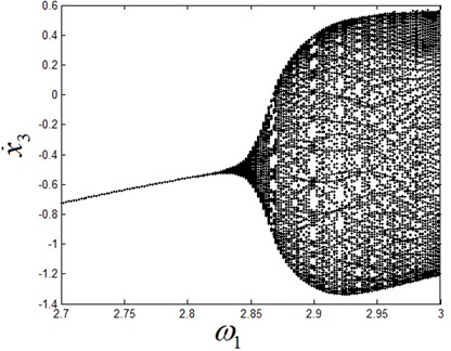
From the characteristic multipliers of Eq. (18), there is a pair of complex conjugated Floquet multiplier is close to the unit circle, i.e. |λ3,4(ωs)|=0.999996≈1, and the rest of the multipliers are in the unit circle. This shows that Neimark-Sacker bifurcation occurs in the system. The bifurcation diagram with varies of ω1 is shown in Fig. 3.
From the Fig. 3, it can be seen that the stable period-1 motion of system exists in the initial interval of ω1 (see Fig. 4). As the parameter ω1 passes through the bifurcation point ωs=2.7724, Neimark-Sacker bifurcation takes place. With the further increase of ω1, the period-1 motion loses its stability and bifurcates to a quasi-periodic motion (see Fig. 5).
Fig. 3Neimark-Sacker bifurcation diagram of the system
3.3. Period-doubling bifurcation
In this section, another set of parameters are taken as: d=0.0001, f1=20, f2=0, m2=1, m3=2, ζ1=0.1, ζ2=0.2, ζ3=0.05, k2=1, k3=20, k4=16, the parameter ω1 is still taken as the bifurcation parameter. The critical bifurcation point ω1=ωs=8.499 can be found on the basis of analysis of Section 3.1 and the corresponding Floquet multipliers of the system at ωs=8.499 are computed as follows:
λ2(ωs)=-0.6571747(|λ2(ωs)|=0.6571747<1)
λ3,4(ωs)=0.7592744±0.5789091i(|λ3,4(ωs)|=0.9547949<1),
λ5,6(ωs)=0.0560869±0.8746048i(|λ5,6(ωs)|=0.8764014<1).
Fig. 4The stable period-1 motion at ω1= 2.75
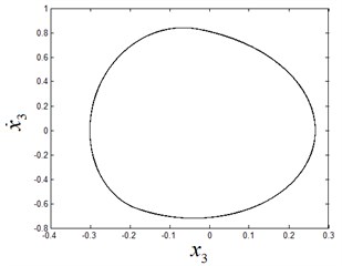
a) The phase diagram
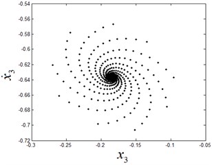
b) The stable focus on Poincaré section
Fig. 5The quasi-periodic motion at ω1= 2.9
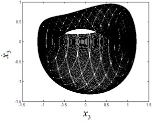
a) The phase diagram
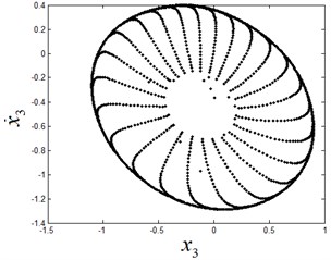
b) The attracting invariant circle on Poincaré section
In Eq. (19), λ1(ωs)=–0.999959 is close to –1, the other Floquet multipliers are still in the unit circle. Thus the period doubling bifurcation occurs in the bearing fault system. Fig. 6 shows a bifurcation diagram for the system.
Fig. 6Period doubling bifurcation diagram of the system
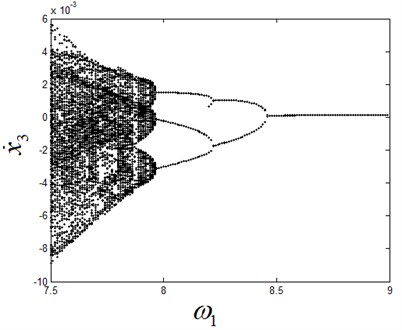
From Fig. 6, the system is in the stable period-1 motion initially. Fig. 7 shows the stable period-1 motion of the system at ω1=8.55. Period doubling bifurcation occurs when ω is decreased gradually and passes through the bifurcation point ω1=8.499, and then the period-2 motion appears, as shown in Fig. 8.
Fig. 7The phase diagram and Poincaré section diagram of period-1 motion at ω1= 8.55
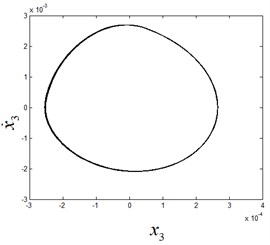
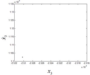
Fig. 8The phase diagram and Poincaré section diagram of period-2 motion at ω1= 8.46
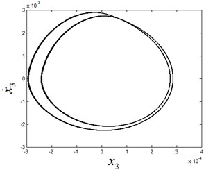
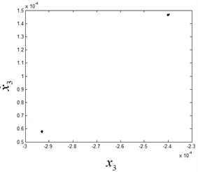
Fig. 9The phase diagram and Poincaré section diagram of period-3 motion at ω1= 8.1
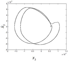
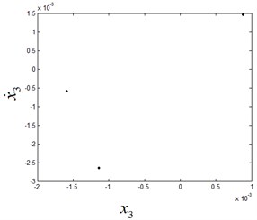
Fig. 10The phase diagram and Poincaré section diagram of quasi-periodic motion at ω1= 7.95
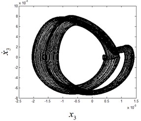
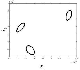
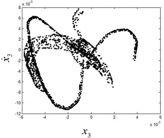
With the decreasing of ω1, the period-3 motion of the system appears, as shown in Fig. 9. When the parameter ω1 is further decreased, the system undergoes Neimark-Sacker bifurcation of period-3 motion and the quasi-periodic motion after bifurcation is shown in Fig. 10. With successive increasing values of the parameter ω1, the system ends up in a chaotic state, as shown in Fig. 11.
Fig. 11The chaotic motion on Poincaré section at ω1= 7.3
4. Conclusions
In this paper we have investigated the bifurcation and chaos of periodic motions of rolling bearing system with outer ring fault. The saltation matrixes at the switching boundaries and the foundation solution matrix in the smooth subspaces are given. Through combining saltation matrixes and foundation solution matrixes, the Neimark-Sacker bifurcation and period-doubling bifurcation of periodic motions of the system are investigated by using Floquet theory. In addition, the phenomenon of Neimark-Sacker bifurcation of periodic three motion and chaotic motion is also revealed in the system. From the results obtained, it is found that the rolling bearing system with fault can exhibit the interesting and complex dynamical behavior. Based on these nonlinear dynamical behaviors of rolling bearing system with fault, the relationship between signal saltation and fault will be revealed from bifurcation perspective by spectral analysis method and Lyapunov exponents method to obtain the set of relevant features of vibration signal in future work. This will provide theoretical basis for fault identification.
References
-
Franklin F. J., Widiyarta I., Kapoor A. Computer simulation of wear and rolling contact fatigue. Wear, Vol. 251, 2001, p. 949-955.
-
Ericsson S., Grip N., Johansson E., Persson L. E., Sjoberg R., Stromberg J. O. Towards automatic detection of local bearing defects in rotating machines. Mechanical Systems and Signal Processing, Vol. 19, 2005, p. 509-535.
-
Sun W., Chen J., Li J. Decision tree and PCA-based fault diagnosis of rotating machinery. Mechanical Systems and Signal Processing, Vol. 21, 2007, p. 1300-1317.
-
Pennacchi P., Vania A., Chatterton S., Tanzi E. Detection of unsteady flow in a Kaplan hydraulic turbine using machine mechanical model and rotor measured vibrations. Proceedings of the ASME Turbo Expo, Copenhagen, Denmark, 2012.
-
He Z. X., Gan H. The study of rolling system dynamics behavior including the bearing shaft clearance. Journal of Vibration and Shock, Vol. 28, Issue 9, 2009, p. 120-124.
-
Zhang W. G., Gao S. H., Long X. H., Meng G. Nonlinear analysis for a machine-tool spindle system supported with ball bearing. Journal of Vibration and Shock, Vol. 27, Issue 9, 2008, p. 72-75.
-
Tang Y. B., Gao D. P., Luo G. H. Non-linear bearing force of the rolling ball bearing and its influence on vibration of bearing system. Journal of Aerospace Power, Vol. 21, Issue 2, 2006, p. 366-373.
-
Gao S. H., Long X. H., Meng G. Three types of bifurcation in a spindle-ball bearing system. Journal of Vibration and Shock, Vol. 28, Issue 4, 2009, p. 59-63.
-
Leine R. I., Nijmeijer H. Dynamics and Bifurcation of Non-Smooth Mechanical Systems. Springer, Berlin, 2004, p. 101-118.
About this article
This work is supported by National Natural Science Foundation of China (11002052).
