Abstract
Unbalance and misalignment are the main causes of vibration in rotating machinery. Vibration analysis is the important tool for fault diagnosis in rotating machinery. In this paper, order analysis technique of vibration analysis for unbalance and misalignment fault diagnosis is proposed. In order analysis, both phase and amplitude are obtained. From phase and amplitude, the fault type and location are usually identified. Experimental results show order analysis is an effective technique for fault diagnosis.
1. Introduction
Rotating machinery plays a significant role in industrial applications. The multiple faults in rotating machinery are unbalance, misalignment, shaft crack, bent shaft, bearing fault, looseness or rubbing, etc. Unbalance and misalignment are most probable faults in rotating machineries [1]. These faults cause a machine to breakdown or reduce the life time of a machine. For fault diagnosis, different techniques are available such as oil analysis, acoustic emission and vibration signal, however, vibration based signal processing technique is most commonly used [2, 3]. As each fault generates a typical vibration pattern and gives typical information of a machine condition, the vibration-based signal processing technique is one of the most important techniques for fault diagnosis in rotating machines.
Unbalance in rotor, also known as rotor unbalance, is the first most common fault in rotating machinery [4, 5]. Unbalance occurs when the mass centre line of a rotor does not coincide with its shaft centre line. The various causes, which are responsible for unbalance, are defects in manufacturing of component (blow holes in casting), unequal weights of rotor blades, corrosion and wear, deposit built-up, high tolerances (clearance) during fabrication and a missing part [6]. Unbalance causes vibration and generates excessive force in the bearing areas and reduces the life span of the bearing. Li et al. [7] developed the expert system to diagnose unbalance using the backward propagation Artificial Neural Network (ANN). The acoustic signals were used as input in ANN. Harsha [8] applied the non-linear dynamic analysis to study unbalance rotor that is supported on roller bearings. They showed the appearance of instability and chaos in the dynamic response as the speed of the system is changed. Sudhakar and Sekhar [9] used two different methods, namely, equivalent loads minimization and vibration minimization methods, for the identification of unbalance fault in a rotor system. Unbalance fault is identified by measuring transverse vibrations at only one location by using equivalent loads minimization and vibration minimization methods.
Misalignment between driver and driven machine shafts is the second most common fault in rotating machinery [4, 10]. Rotor misalignment occurs because of improper alignment of couplings, thermal distortion of a bearing-housing supports and asymmetry in the applied load. Hili and Haddar [11] studied misalignment and unbalance faults of rotor using equations of motion. The resolution of the equation of motion by the spectral method permits the analysis of dynamic response of flexible rotor subjected to unbalance and misalignment. Patel and Darpe [4] investigated the effect of misalignment (parallel and angular) on vibration signals of coupled rotors. They found the misalignment couples vibration in bending, longitudinal and torsional modes. Further, Patel and Darpe [12] carried out experimental investigation of misaligned rotors using vibration signals; the unique nature of misalignment fault was effectively reported using full spectra and orbit plots. Jalan and Mohanty [13] used a model based technique, which is based on residual generation technique, for identification of misalignment and unbalance faults. The fault condition and location of faults are successfully detected by using this technique.
In this paper, order analysis technique for unbalance and misalignment fault diagnosis is proposed. Phase and amplitude are obtained from order analysis. The phase signal analysis provides further insight into machine diagnostics in conjunction with the information initially provided by the FFT.
2. Experimental set-up
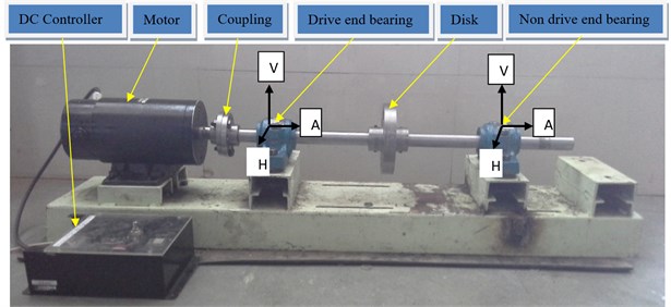
The experiments were carried out on a test-rig as shown in Fig. 1. The test-rig consists of a shaft (25 mm diameter and 700 mm length) that is supported using two double row deep groove ball bearings (SKF1205). One rotor disk of 130 mm diameter and 18 mm thick is fixed at the mid span of bearings. The rotor disk has eight equally spaced holes of 12 mm diameter at 45 mm radius to create and unbalance by fixing a mass. The rotor is driven by 1 HP DC motor and speed is controlled by DC controller. The motor shaft (driver shaft) and rotor shaft (driven shaft) are connected using the rigid flange coupling. The operating speed of rotor was kept at 1000 rev/min.
Fig. 1Actual photograph of rotor test Rig

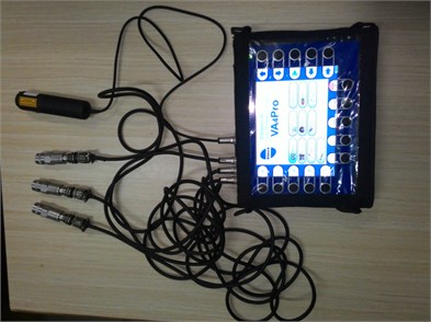
Fig. 2Photograph of FFT analyzer

The piezoelectric accelerometer (Make: CTC; Model: AC102-1A) having (sensitivity = 100 mV/g) is used to collect the vibration signals in horizontal (H), vertical (V) and axial (A) direction at bearing-housing (Fig. 2). The four channel FFT analyzer (Make: Adash; VA4Pro) is used to collect vibration signals and carry out analysis. Velocity is the most common parameter for vibration analysis, as most machines and their defects generate vibrations in the frequency range of 10 Hz (600 CPM or rev/min) to 1 kHz (60000 CPM or rev/min). Velocity RMS (mm/s) parameter is selected for vibration measurement [14].
3. Results and discussions
In the present work, unbalance and misalignment fault diagnosis and case study of fault diagnosis of boiler feed water pump using order analysis is carried out. The vibrations are measured at drive end (DE) bearing and non drive end (NDE) bearing in vertical, horizontal and axial directions.
3.1. Vibration response of unbalanced rotor
The unbalanced fault was created by attaching 12 g mass at 45 mm radius on the rotor. RMS values of first order in vertical, horizontal and axial directions are given in Table 1. RMS value along horizontal direction is high compared to vertical and axial vibration is as shown in Table 1. The reason is that the vertical bearing stiffness is usually higher than that in horizontal direction, the normal response of shaft and bearing is slightly elliptical orbit. The order spectrum of unbalanced rotor at drive-end bearing in vertical direction, DE-V (Fig. 3), horizontal direction, DE-H (Fig. 4) and axial direction, DE-A (Fig. 5) are shown. The order spectrum of unbalanced rotor at non drive-end bearing in vertical direction, NDE-V (Fig. 6), horizontal direction, NDE-H (Fig. 7) and axial direction, NDE-A (Fig. 8) are shown. Order spectrum show that the higher amplitude obtained at first order, i.e., 1000 rev/min. The reason is that the centrifugal force caused by the unbalance rotates with the rotational frequency and causes forced vibrations with the same frequency.
Table 1RMS values of first order in horizontal, vertical and axial directions at DE bearing and NDE bearing
Speed (rev/min) | RMS amplitude (mm/s) | |||
Bearing end | Direction | |||
Vertical | Horizontal | Axial | ||
1000 | DE | 1.23 | 5.75 | 0.832 |
NDE | 1.75 | 7.47 | 1.15 | |
Fig. 3Order spectrum of unbalanced rotor at drive end in vertical direction (DE-V)

Fig. 4Order spectrum of unbalanced rotor at drive end in horizontal direction (DE-H)

Fig. 5Order spectrum of unbalanced rotor at drive end in axial direction (DE-A)

Fig. 6Order spectrum of unbalanced rotor at non drive end in vertical direction (NDE-V)

Fig. 7Order spectrum of unbalanced rotor at non drive end in horizontal direction (NDE-H)

Fig. 8Order spectrum of unbalanced rotor at non drive end in axial direction (NDE-A)

Phase values in horizontal, vertical and axial directions as shown in Table 2. Phase difference observed between horizontal and vertical direction on DE and NDE bearing is 96.4° and 64.3°, i.e., 90°±30°. Phase difference between vertical-vertical direction at DE and NDE bearing is 20.9°, i.e., 0°±30° and 11.4°, i.e., 0°±30° in horizontal-horizontal direction. These results indicate the unbalance present in the system.
Table 2Phase values of first order in horizontal, vertical and axial directions at DE bearing and NDE bearing
Direction | DE bearing (degree) | NDE bearing (degree) | Phase difference between V and H at DE bearing (degree) | Phase difference between V and H at NDE bearing (degree) | Phase difference at DE and NDE bearing (degree) |
V | 0.6 | 21.5 | 96.4 | 64.3 | 20.9 (V and V) |
H | 97.2 | 85.8 | 11.4 (H and H) | ||
A | –128 | –145.6 |
3.2. Vibration response of misalignment fault
Angular misalignment of 0.8° is created in coupling. RMS values of first order in vertical, horizontal and axial directions are given in Table 3. Vibration level along axial direction is high compared to vertical and horizontal vibration. The order spectrum of angular misalignment at drive-end (DE) bearing in vertical direction (Fig. 8), horizontal direction (Fig. 9) and axial direction (Fig. 10) are shown. Angular misalignment generates a strong vibration at first order, i.e., 1000 rev/min and some vibration at second, i.e., 2000 rev/min in the axial direction. There has also been fairly strong radial (vertical and horizontal) first order and second order vibration levels.
Table 3RMS values of first order in vertical, horizontal and axial directions at DE bearing
Speed (rev/min) | RMS amplitude (mm/s) | |||
Bearing end | Direction | |||
Vertical | Horizontal | Axial | ||
1000 | DE bearing | 2.32 | 1.17 | 6.03 |
Fig. 9Order spectrum of angular misalignment at drive end in vertical direction (DE-V)

Fig. 10Order spectrum of angular misalignment at drive end in horizontal direction (DE-H)

Fig. 11Order spectrum of angular misalignment at drive end in axial direction (DE-A)

The phase values in horizontal, vertical and axial directions across coupling as shown in Table 4. A phase difference 160°, i.e., 180°±30° observed when axial measurements on the motor drive-end (MDE) bearing and DE bearing across the coupling [14]. These results indicate that the angular misalignment present in the shaft.
The parallel misalignment of 0.1 mm was created in coupling. RMS values of first order in horizontal, vertical and axial directions at DE bearing are shown in Table 5. The order spectrum of parallel misalignment at drive-end (DE) bearing in vertical direction (Fig. 11), horizontal direction (Fig. 12) and axial direction (Fig. 13) are shown. Order spectra show higher amplitude at second order (2000 rev/min) in the radial direction.
Table 4Phase values of first order in vertical, horizontal and axial directions at MDE bearing and DE bearing
Direction | MDE bearing (degree) | DE bearing (degree) | Axial phase difference at MDE and DE bearing (degree) |
V | 48.4 | 45.1 | 160 |
H | –112.9 | –112.4 | |
A | 74 | –126 |
Table 5RMS values of first order in vertical, horizontal and axial directions at DE bearing
Speed (rev/min) | RMS amplitude (mm/s) | |||
Bearing end | Direction | |||
Vertical | Horizontal | Axial | ||
1000 | DE bearing | 1.79 | 1.96 | 0.539 |
Fig. 12Order spectrum of parallel misalignment at drive end in vertical direction (DE-V)

Fig. 13Order spectrum of parallel misalignment at drive end in horizontal direction (DE-H)

Fig. 14Order spectrum of parallel misalignment at drive end in axial direction (DE-A)

Table 6Phase values of first order in vertical, horizontal and axial directions at MDE bearing and DE bearing
Direction | MDE bearing (degree) | DE bearing (degree) | Vertical phase difference at MDE and DE bearing (degree) |
V | 103.4 | –65 | 168.4 |
H | –67.2 | –58.8 | |
A | –2 | 115.2 |
Phase values in horizontal, vertical and axial directions across coupling as shown in Table 6. A phase difference 168.4°, i.e., 180°±30° observed when vertical measurements on the motor drive end bearing and drive end bearing across the coupling [14]. These results indicate that the parallel misalignment present in the shaft.
4. Case study
Case study of fault diagnosis of boiler feed water pump of sugar factory is carried out. Order analysis technique is used for fault diagnosis.
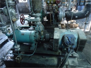
Fig. 15Photograph of boiler feed pump

The photograph of boiler feed water pump is as shown in Fig. 15. Specification of boiler feed water pump shown in Table 7.
Table 7Specification of boiler feed water pump
Make | KSB pumps Ltd. |
Discharge | 35 m3/h |
Head | 300 m |
Speed | 2940 rev/min |
No. of impeller | 7 |
Driven | Induction motor |
Power | 75 Hp |
Speed | 2940 rev/min |
4.1. Vibration response of boiler feed water pump
RMS values of first order in vertical, horizontal and axial directions at DE and NDE bearing are given in Table 8. RMS value along horizontal direction is high compared to vertical and axial vibration is as shown in Table 8. The order spectrum at drive-end bearing in vertical direction, DE-V (Fig. 16), horizontal direction, DE-H (Fig. 17) and axial direction, DE-A (Fig. 18) are shown.
Table 8RMS values of first order in horizontal, vertical and axial directions at DE and NDE bearing
Speed (rev/min) | RMS amplitude (mm/s) | |||
Bearing end | Direction | |||
Vertical | Horizontal | Axial | ||
2940 | DE | 6.92 | 11.9 | 1.14 |
NDE | 1.61 | 2.49 | 1.05 | |
Order spectrum show that the higher amplitude obtained at first order, i.e., 2940 rev/min. Phase difference observed between horizontal and vertical direction on bearing is 100.1° i.e., 90°±30°. These results indicate the unbalance present in the system.
Fig. 16Order spectrum at drive-end bearing in vertical direction (DE-V)

Fig. 17Order spectrum at drive end bearing in horizontal direction (DE-H)

Fig. 18Order spectrum at drive end bearing in horizontal direction (DE-A)

5. Conclusions
Experimental investigation of unbalance and misalignment fault by order analysis is carried out and following conclusions are drawn:
1) Unbalance: overall RMS value in horizontal direction is high compared to vertical direction. First order amplitude is predominant. The phase from vertical to horizontal measurements differs by 90°±30° on DE and NDE bearing.
2) Angular misalignment: It is observed that the highest value of RMS amplitude is produced in axial direction as compared to vertical and horizontal direction. A 180°±30° phase difference observed when measuring the axial measurements on the motor drive end bearing and DE bearing across the coupling.
3) Parallel misalignment: It is observed that the RMS value at second order is high. A phase shift is 180°±30° observed across the coupling.
References
-
Reddy M. C. S., Sekhar A. S. Application of artificial neural networks for identification of unbalance and looseness in rotor bearing systems. International Journal of Applied Science and Engineering, Vol. 11, Issue 1, 2013, p. 69-84.
-
Chen C. S., Chen J. S. Rotor fault diagnosis system based on sGA-based individual neural networks. Expert Systems with Applications, Vol. 38, 2011, p. 10822-10830.
-
Sinha J. K. Vibration-based diagnosis techniques used in nuclear power plants: an overview of experiences. Nuclear Engineering and Design, Vol. 238, 2008, p. 2439-2452.
-
Patel T., Darpe A. Vibration response of misaligned rotors. Journal of Sound and Vibration, Vol. 325, 2009, p. 609-628.
-
Walker R. B., Vayanat R., Perinpanayagam S., Jennions I. K. Unbalance localization through machine nonlinearities using an artificial neural network approach. Mechanism and Machine Theory, Vol. 75, 2014, p. 54-66.
-
De Silva C. W. Vibration Monitoring, Testing, and Instrumentation. CRC Press, Taylor and Francis Group, New York, 2007.
-
Li W., Tsai Y. P., Chiu C. L. The experimental study of the expert system for diagnosing unbalances by ANN and acoustic signals. Journal of Sound and Vibration, Vol. 272, 2004, p. 69-83.
-
Harsha S. P. Nonlinear dynamic analysis of an unbalanced rotor supported by roller bearing. Chaos, Solitons and Fractals, Vol. 26, 2005, p. 47-66.
-
Sudhakar G. N. D. S., Sekhar A. S. Identification of unbalance in a rotor bearing system. Journal of Sound and Vibration, Vol. 330, 2011, p. 2299-2313.
-
Zhang J., Ma W., Lin J., Ma L., Jia X. Fault diagnosis approach for rotating machinery based on dynamic model and computational intelligence. Measurement, Vol. 59, 2015, p. 73-87.
-
Hili M. A., Fakhfakh T., Haddar M. Failure analysis of a misaligned and unbalanced flexible rotor. Journal of Failure Analysis and Prevention, Vol. 6, Issue 4, 2006, p. 73-82.
-
Patel T., Darpe A. Experimental investigations on vibration response of misaligned rotors. Mechanical Systems and Signal Processing, Vol. 23, 2009, p. 2236-2252.
-
Jalan A., Mohanty A. R. Model based fault diagnosis of a rotor-bearing system for misalignment and unbalance under steady-state condition. Journal of Sound and Vibration, Vol. 327, 2009, p. 604-622.
-
Scheffer C., Girdhar P. Practical Machinery Vibration Analysis and Predictive Maintenance. First Edition, Newnes, 2004.
