Abstract
In this paper, a measuring system based on binocular vision is developed for the research on large-caliber gun muzzle vibration. The system is consisted of two high-speed cameras and other equipment. The two-step calibration method based on radial constraint is adopted in order to complete the calibration, the inter-frame differential multiplication method is used to detect the centroid of moving target accurately, the improved Kalman filter tracking algorithm is used to obtain the motion trajectory of the muzzle identification point. The system is applied to practice for a type of muzzle vibration measurement and meaningful original data is acquired.
1. Introduction
In the projectile firing process, the great expansion force produced by propellant transient combustion, the friction of the relative movement between the projectile and gun and the inertia force of gun will lead to the muzzle vibration. The vibration response will directly affect the target lethality and the precision of the gun. Since many factors will influence the measuring instrument range and precision, such as the gun firing instantaneity, the muzzle space displacements and the interference of the muzzle flame and smoke, non-contact measuring method is usually adopted in the muzzle vibration responses detection. The conventional non-contact measurements such as displacement sensor or laser vibration can only be applied for the small caliber gun and one-dimensional motion testing, when facing with large caliber artillery and complex three dimensional motion form, accurate data is hard to obtain.
2. Theoretical background
Single camera will lost object depth information in the imaging process. In order to reconstruct three-dimensional information of space object, two cameras are needed to shoot the same image. In actual measurement, if the relative position information of the two cameras in the world coordinate system is known, the three-dimensional information can be measured in the field of space objects according to the triangle principle.
Fig. 1Binocular vision
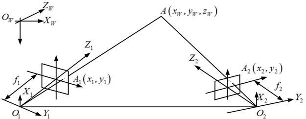
The binocular vision schematic is shown in Fig. 1, where A(xw,yw,zw) is any point in the space, two cameras’ coordinate system are (x1,y1,z1) and (x2,y2,z2), and two cameras’ image coordinate system are (X1,Y1) and (X2,Y2), the effective focal length of two cameras are f1 and f2, so:
The 3-D coordinates of point in the left camera in space can be expressed as Eq. (4):
The relationship between the world coordinate system and the two camera coordinate system can be can be expressed as following:
[x2y2z2]=R2[xwywzw]+T2,
3. Methods
3.1. Experimental system
The measurement system is shown in Fig. 2. The measurement system used in this study includes two high-speed cameras, camera lens, cables and triggers. The VISION RESEACH’s Phantom v1610 and the NIKON 400 mm f/2.8D IF-ED AF-S II Nikkor are used to build the system. In considering of the effects of muzzle blast wave, field illumination conditions and field real terrain, two high-speed cameras are placed on one side of the ground artillery and the distance between them is 20 meters, the vertical distance from the camera to the gun is 20 meters. Cameras and other equipment are connected by cables.
3.2. Experiment procedure
3.2.1. Calibration
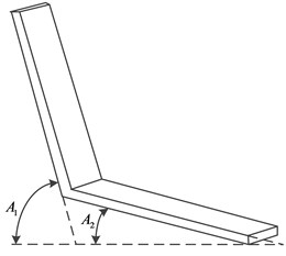
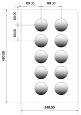
The calibration model which is self-made is fixed on one side of the muzzle by fixing device, and two cameras take the picture of the model from different perspectives at the same time. After the pictures of the model are acquired, in order to determine the external and internal parameters of two cameras, the two-step calibration method based on radical constraint is adopted.
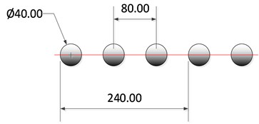
The calibration model is shown in Fig. 3, in a) A1=75°, A2= 15°; in b) the size of each plate is 2400×4800 mm, the number of the mark point is 20; in c) the diameter of the mark point is 40 mm and the center distance between each point is 80 mm. Fig. 4 shows the picture taken by the two cameras.
Fig. 2Measurement system
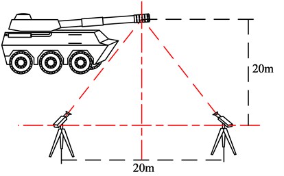
Fig. 3Calibration model
a)
b)
c)
Fig. 4Calibration pictures

a) Picture from left camera

b) Picture from right camera
3.2.2. Image acquisition
The Phantom Camera Control Application is used to control two high-speed cameras. And the resolution of the camera is 1280×500, the sample rate is 10000 pps, the exposure time is 15 μm.
3.2.3. Target detection
In this paper, the inter-frame differential multiplication method is used to segment the video image sequences of two cameras. The method can produce the high correlation peak, which not only can effectively avoid the false moving targets, but also can amplify the difference between target area and background value and strengthen the movement of the target area.
The equation of Inter-frame differential multiplication used in the paper:
where f1(x,y), f2(x,y), f3(x,y), f4(x,y) denote the four adjacent frames respectively, G(x,y) is the result as pixel value.
3.2.4. Target tracking
Improved kalman filter tracking algorithm is used to obtain the motion trajectory of the muzzle identification point, in which the centroid of moving target is regarded as the observed value input. The algorithm obtain the moving target through the estimation and correction of it’s centroid position.
To restrain the divergence of Kalman filter, improved Kalman filter tracking algorithm based on fading factor is proposed. The algorithm expand the priori estimate covariance P-(k), offset the error accumulation and improve the estimation accuracy and robustness of the Kalman filter. The fading factor and the scalar factor are used:
H(k)'=αkH(k).
where ηk is the fading factor, αk is the scalar factor, the new Kalman gain matrix is:
The optimal value of αk can generally be used in window estimation method which is estimated as:
H(k)'={ηk-1NiNiT1+ηk-1,k>1,12N0N0T,k=1.
And the optimal value of the fading factor ηk can be estimated as:
3.3. Results and analysis
3.3.1. Calibration information
The calibration results of two cameras are as follows:
Left camera:
Right camera:
3.3.2. Target detection
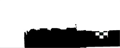
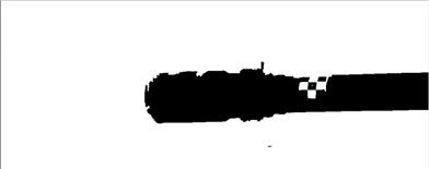
To achieve the target region accurately, the inter-frame differential multiplication method is used for the video image sequence of two cameras through different perspectives. To calculate the centroid coordinate, the mathematical morphology filtering, connected domain analysis and feature extraction are used in the image processing. The results are shown in Fig. 5.
Fig. 5Target detection
a) Picture from left camera
b) Picture from right camera
3.3.3. Target tracking
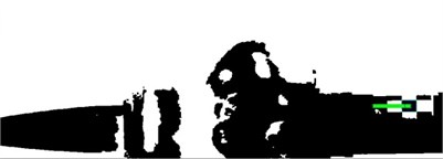
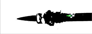
The centroids of the target are used as the input value in the Kalman filter target tracking model, and fading factor is introduced to increase the weight of new information and avoid the divergence of Kalman filter. The results are shown in Fig. 6.
Fig. 6Target tracking
a) Picture from left camera
b) Picture from right camera
3.3.4. Three dimensional measurement
In the paper, the world coordinate system is determined by the calibration model, the origin of coordinates and coordinate axis shows in Fig. 7. The X axis is parallel to the direction of the muzzle, the Y axis is parallel with the ground and pointing to the cameras, and the Z axis is perpendicular to the muzzle direction and pointing to the sky.
Fig. 7World coordinate system

The muzzle vibration displacement curve in the two dimensional coordinate shows in Fig. 8.
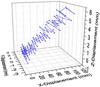
The three-dimensional displacement coordinate displacement curve shows in Fig. 9.
According to the results, due to the recoil of the gun, the muzzle vibration displacement curve in the X axis direction is rising and constant moving backward, in the Y axis direction is a continuous shock curve, which representing the swing shift and in the Z axis direction is a rising curve which represented the displacement in vertical direction, but the increase is far less than that in the X axis direction.
Fig. 8The muzzle vibration displacement curve
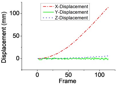
Fig. 9The muzzle vibration displacement curve
4. Conclusions
To resolve the problem of conventional measurement methods , the paper realize the research and improvement on the measuring method of large caliber gun muzzle vibration, in which the binocular vision measurement method is applied to practice for a type of muzzle vibration measurement in practice. The measurement result provides meaningful original data support for the gun performance improvement and gun model development.
References
-
Marr D. Vision. Freeman and Company, Oxford, 1982.
-
Badenas Jorge, Bober M., Pla F. Motion and intensity-based segmentation and its application to traffic monitoring. International Conference on Image Analysis and Processings, Florence, Italy, 1997, p. 502-509.
-
Jang D.-S., Choi H.-I. Active models for tracking moving objects. Pattern Recognition, Vol. 33, Issue 7, 2000, p. 135-1146.
-
Vallerand Steve, Kanbara Masayuki, Yokoya Naokazu Binocular vision-based augmented reality system with an increased registration depth using dynamic correction of feature positions. Proceedings of the IEEE Virtual Reality, 2003.
-
Tsai R. Y. A versatile camera calibration technique for high-accuracy 3D machine vision metrology using off-the-shelf cameras and lens. IEEE Transactions on Robotics and Automation, Vol. 3, Issue 4, 1987, p. 323-344.
-
Kim J. S., Kim H. W., Kweon I. S. A camera calibration method using concentric circles for vision applications. The 5th Asian Conference on Computer Vision, 2002, p. 515-520.
-
Zhang Z. Y. A flexible new technique for camera calibration. IEEE Transactions on Pattern Analysis and Machine Intelligenee, Vol. 22, Issue 11, 2000, p. 1330-1334.
-
Serra J. Image Analysis and Mathematical Morphology. Vol. l. Academic Press, New York, 1982.
-
Ragulskis M., Maskeliunas R., Saunoriene L. Identification of in-plane vibrations using time average stochastic Moire. Experimental Techniques, Vol. 29, Issue 6, 2005, p. 41-45.
-
Kalman R. E. A new approach to linear filtering and prediction problems. Journal of Basic Engineering, Vol. 82, Issue 1, 1960, p. 35-45.
About this article
This is supported by the National Key Scientific Instrument Development Projects, No. 2013YQ470765.
