Abstract
A new dual-excitation fatigue loading system of wind turbine blades was designed in this paper. However, the two excitations and blade constituted a complicated non-liner energy transferring system in which the vibration coupling effect would influence the sequent accurate control of fatigue test. To study the mechanism of the coupling system mentioned above, the electromechanical coupling mathematical model was established by simplifying the loading system rationally and the factors affecting the vibration coupling were obtained accordingly. Then the simulation model of the system was built in Matlab/Simulink environment to mainly analyze the basic influence laws of the motor speed and the initial phase difference of two excitations. Finally, a small dual-excitation fatigue loading system was established to verify the correctness of the mathematical and simulation model. It could be concluded that the results of on-site test were consistent with the results of simulation.
1. Introduction
As an important renewable energy technology, wind power generation has many ecological and economic benefits. According to the report Technology Roadmaps – Wind energy released by International Energy Agency, by the mid-21st century, the proportion of wind power generation in global power supply will rise from the present 2 % to 12 % [1]. Ina wind turbine generator, blades are the main part bearing the wind power. A large number of accidents and research results show that due to the impact of alternating load, fatigue is one of the main failure mechanisms for blades [2-3]. Thus, fatigue test of a wind turbine blade is an effective and reliable method to detect weaknesses in a blade’s design [4].
Fatigue tests on blades are typically conducted by imposing an excitation mounted at 70 % of the blade length along the span wise direction and making the blade and excitation resonate together [5]. However, this test method has deficiencies of long test cycle and lacking of driving capability etc. In this paper, a dual-excitation fatigue loading system of wind turbine blades was developed to solve the problems mentioned above. However, the two excitations and blade constitute a complicated non-liner energy transferring system, in which the vibration coupling effect will influence the distribution of flexural moment and resonance of whole system and further more lead to inaccurate control of fatigue test. So the coupling mechanism of dual-excitation fatigue loading system need to be investigated.
For dual-excitation vibration system, Blekhan first proposed the synchronous control theory of dual-excitation vibration machine [6]. After that, the coupling characteristics of dual-exciter vibration mechanical system have been investigated by many researchers [7-10]. However, from the current literatures, it could be concluded that in the field of fatigue loading tests for wind turbine blades, studies on the vibration coupling mechanism of two exciters have not been carried out both in domestic and abroad.
2. Electromechanical coupling mathematical model of the dual-excitation fatigue loading system of wind turbine blades
2.1. Establishing the mathematical model the mechanical vibration system
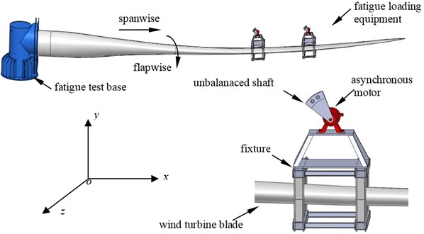
The dual-excitation fatigue loading test system consisted of a loading test base, wind turbine blade and fatigue loading equipment. The root of the blade was fixed by high strength screw bolts to the loading base which was mounted on the ground. Two set of fatigue loading equipment were mounted on the blade along the span wise direction. The fatigue loading equipment mainly included an unbalanced shaft, three-phase asynchronous motor, fixture, gear box, and electric control equipment. The fatigue loading system is shown in Fig. 1.
Fig. 1Dual-excitation fatigue loading system of wind turbine blades
The dynamic model of the dual-excitation fatigue loading system is shown in Fig. 2. In order to simplify the system, it was assumed that the damping force suffered by the blade in each direction was a linear function of the velocity, and the elastic force was also a linear function of the displacement.
Fig. 2Dynamic model of dual-excitation fatigue loading system of wind turbine blades
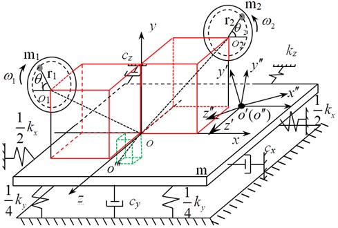
In Fig. 2, oxyz is the absolute coordinate system, o'x'y'z' and o''x''y''z'' are the moving coordinate system, o''' is the centroid of the whole vibration system (include the blade and the two set of loading equipment), m is the total weight of the blade and two sets offatigue loading equipment. oi is the rotary center of the unbalanced shaft i, mi is the weight of the unbalanced shaft i, ri is the equivalent arm length of the unbalanced shaft i, θi and ωi are the rotary angle and angular velocity of the the unbalanced shaft i and ωi=˙θi (i= 1, 2).
x, y, z, φi and θi (i= 1, 2)were regarded as generalized coordinates, then according to Lagrange equation[11], the dynamic equation of the dual-excitation fatigue loading system is established as follows:
where, φi is the included angle of oxyz and two moving coordinate system, respectively, li1 is the projection of ooi in the plane yoz and li2 is the projection of ooi in the plane xoy. βi1 is the include dangle of li1 and the positive direction of z-axis, βi2 is the included angle of li2 and the positive direction of x-axis and β0i is the include dangle of l0i and the negative direction of y-axis, kx,…, ky, kz and kφi are the stiffness coefficient of x, y, z and φi direction, respectively, cx, cy, cz and cφi are the damping coefficient of x, y, z and φi direction, respectively, Joi is the rotational inertia of the system around x axis and z axis, Ji is the rotational inertia of the asynchronous motor i, Tmi is the electromagnetic torque of the shaft of the asynchronous motor i (i= 1, 2 for all the parameters above). l01 and l02 are the projection of oo''' in the plane yoz and plane xoy, respectively.
2.2. The mathematical model of three-phase asynchronous motor
In the fatigue loading equipment, each unbalanced shaft was driven by a three-phase asynchronous motor, which would generate the loading force. So the mathematical model of the three-phase asynchronous-motor was also needed to be built. However, the model of asynchronous motor in the case of three-phase was complicated, so in practice, the mathematical model based on two-phase synchronous rotating coordinate system αβ was applied to represent the original model in abc system [12].
The coordinate transformation equation of three-phase asynchronous motor from abc system to αβ system is expressed by:
The voltage equation of three-phase asynchronous motor based on αβ system is expressed by:
The flux linkage equation of three-phase asynchronous motor based on αβ system is expressed by:
The electromagnetic torque and the load torque equation is expressed by:
where, r1 and r2 are the winding resistance of the stator and the rotor, iα1 and iβ1 are the terminal currents of the stator in αβ system, iα2 and iβ2 are the terminal currents of the rotor in αβ system, uα1 and uβ1 are the terminal voltages of the stator in αβ system, uα2 and uβ2 are the terminal voltages of the rotor in αβ system. ωr is the angular velocity of the rotor, Ψα1 and Ψβ1 arethe flux linkage of the stator in αβ system, Ψα2 and Ψβ2 arethe flux linkageof the rotorin αβ system, Ls and Lr are the self-inductance of the stator and rotor winding resistance, Lm is the mutual-inductance of the stator and rotor winding, Te is the electromagnetic torque, TL is the load torque, np is the number of pole pairs, p is the differential operator.
Eqs. (1)-(6) constituted the electromechanical coupling mathematical model of the dual-excitation fatigue loading system of wind turbine blades. This mathematical model was a non-ideal space coupling model and described the space coupling effect between the power system and vibration system during the loading process. It could be seen that the rotary driving speeds of motors, the initial phase difference of two unbalanced shafts and the mechanical properties of asynchronous motors, etc. were the factors affecting the vibration coupling.
3. Simulation analysis of the vibration coupling process
For the limited space, the influence law of driving speeds of motors and the initial phase difference of two unbalanced shafts were analyzed in simulation software Matlab/Simulink. Considering the sequent on-site test condition, the parameters of a small wind turbine blade were adopted for simulation. Moreover, symmetric installation was applied for the two set of loading equipment and the symmetric center was the point located at 70 % of the blade length along the span wise direction, namely l12 was equal to l22 in Eq. (1).
The parameters of simulation were set: m= 29 kg, m1=m2=2 kg, r= 0.15 m, l01= 0.05 m, l02=0.25 m, l11=l21=0.13 m, l12=l22= 0.32 m, β01=45°, β02=2.5°, β11= 42°, β12=160°, β21=138°, β22= 20°.
The initial phase difference of two unbalanced shafts was set to π/2. The rotary driving speeds of two asynchronous motors were the same and set to 150 r/min, 180 r/min, 210 r/min, 230 r/min and 260 r/min, respectively. The simulation result is shown in Fig. 3.
Fig. 3Phase difference change curve sat different rotary driving speed of the motors
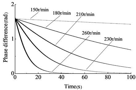
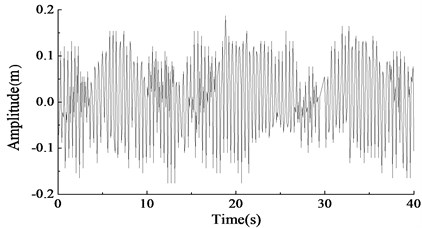
In Fig. 3, under different rotary driving speeds, phase differences of two unbalanced shafts all gradually converged to zero. When the driving speeds of motors were 260 r/min, the phase difference converged to zero with the shortest time, about 40 s. As speeds decrease, more time would be needed for phase difference converging to zero. When the rotary driving speeds were 150 r/min, the phase difference converged to zero with long time, over 100 s. Furthermore, when the rotary driving speeds were 260 r/min, with the phase difference gradually converging to zero, the amplitude in y direction become stabilizing after a period of fluctuation, and the simulation result is shown in Fig. 4.
Fig. 4The amplitude in y direction, the rotary driving speed = 260 r/min
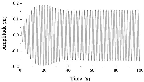
When the rotary driving speeds of motors were set to 230 r/min and the initial phase difference of two unbalanced shafts was set to –5π/6, –π/2, –π/6, π/6, π/2, 5π/6 and π, respectively. The simulation result is shown in Fig. 5.
In Fig. 5, the phase differences of the two unbalanced shafts gradually converged to zero after a period of time even the initial values were a bit large. However, when the initial value was π, the phase difference would converge to zero with longer time compared to others, and the vibration system is difficult to achieve the synchronization status. To obtain more stable amplitude, it should be avoid that the initial phase difference of the two unbalanced shafts was π.
When the rotary driving speeds of the two asynchronous motors were different from each other and set to 230 r/min and 217 r/min, respectively, the simulation result of the phase difference is shown in Fig. 6, and the amplitude result in y direction is shown in Fig. 7.
Fig. 5Phase difference change curves under different initial values, the rotary driving speed = 230 r/min
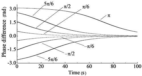
Fig. 6The phase difference simulation result of two unbalanced shafts driven by different speeds
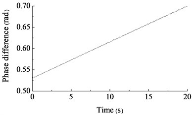
Fig. 7The amplitude simulation curve in y direction under the different speed of two motors
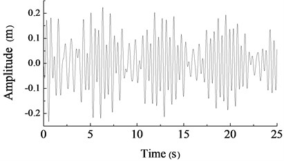
In Fig. 6 and Fig. 7, if the initial rotary driving speeds of two unbalance shafts were high and their speed difference was large, the two set of fatigue loading equipment could not achieve synchronization status and the amplitude in y direction could not stabilize. To obtain stable amplitude, the rotary driving speeds of two asynchronous motors should be as similar as possible, so the synchronized control of two loading sources was indispensable.
4. Test verification
To verify the correctness of the theoretical analysis and the simulation results, a small-scale dual-exaction fatigue loading system of a wind turbine blade was established. The on-site test is shown in Fig. 8 and part of test parameters is shown in Table 1.
Table 1Test parameters
Parameter | Value (or type) |
Length of the blade | 2.3 m |
Weight of the blade (kg) | 25 |
Weight of the unbalanced shaft (kg) | 2 |
Equivalent arm length of the unbalanced shaft (m) | 0.15 |
Power of the motor (kw) | 0.75 |
Temperature (°C) | 15 |
Humidity (RH) | 40 % |
The rotary driving speeds and phases of two unbalanced shafts were measured real-time by gear speed sensors (type: CORON-CTS). Gears with 120 teeth were installed on the motor shaft so that the gears and the motor shaft can rotate synchronously. During the measuring, each gear speed sensor produced a pulse when a tooth of gear was detected, so the driving speeds and phases of the unbalanced shafts could be obtained. A proximity switch was installed below every unbalanced shaft to realize the reset of phase. The amplitude in y direction was measured by a laser range meter (type: ADSL-30) and the amplitude data was transferred real-time to the controller.
In this paper, Siemens S7-200 PLC was applied as the controller which calculated and analyzed the received gear pulses and amplitude data, then transmitted them to the host computer via RS485 bus. The interface of host computer was designed by LabVIEW.
During the test process, the rotary driving speeds of the two asynchronous motors were both set to 230 r/min, and the initial phase difference of the two unbalanced shafts was set to π/6. For other parameters, see the set of parameters in simulation section. The test results are shown in Fig. 9 and Fig. 10.
Fig. 8Dual-excitation fatigue loading test of a wind turbine
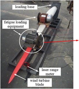
a) The whole test scene
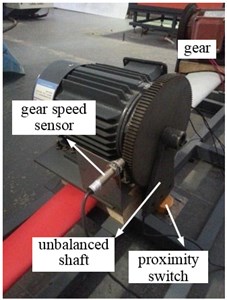
b) Partial enlarged
Fig. 9Test curve of phase difference
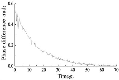
Fig. 10The amplitude test curve in y direction
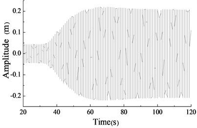
In Fig. 9 and Fig. 10, the phase difference of two unbalanced shafts gradually converged from π/6 to zero. And the amplitude in y direction gradually tended to be stable and finally kept between ±0.25 m.
When the rotary driving speeds of two asynchronous motors were different and set to 230 r/min and 217 r/min, respectively, the test result are shown in Fig. 11 and Fig. 12.
The test result showed that the phase difference of two unbalanced shafts gradually increased if their initial driving speed difference was large. And the amplitude of the blade in y direction was disordered. The two set of fatigue loading equipment were difficult to achieve the synchronization status automatically. The test results above were consistent with the simulation results basically.
Fig. 11The phase difference test result of two unbalanced shafts driven by different speeds
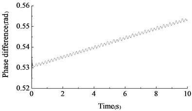
Fig. 12The amplitude test curve in y direction under the different speed of two motors
5. Conclusion
The vibration characteristics of dual-excitation fatigue loading system of wind turbine blades was investigated, conclusions can be drawn as follows:
1) By establishing the electromechanical coupling mathematical model of the dual-excitation fatigue loading system, it was found that the main factors influencing the coupling characteristics included the initial phase difference, rotary driving speed and eccentric moment of two unbalanced shafts, the location of two set of fatigue loading equipment and the mechanical properties of asynchronous motor etc.
2) By establishing the simulation model in simulation software Matlab/Simulink, the phase differences of the two unbalanced shafts and the amplitude of the blade in y direction was obtained visually.When the rotary driving speeds of two asynchronous motors were the same, the phase difference of two unbalanced shafts gradually converged to zero, even the initial phase difference of them was not zero. What more, the higher the driving speed of motor was, the faster the phase difference converged to zero. Finally, the vibration system could step into synchronous status and at the vibrating direction, the stable amplitude could be obtained. However, it should be avoid that the initial phase difference of the two unbalanced shafts was π because a long period of time would be needed to reach the vibration synchronous status.When the initial rotary driving speeds of two asynchronous motors were high and their speed difference was large, the two set of fatigue loading equipment could not achieve synchronization status and the amplitude in y direction was disordered.
3) The results of the on-site test were consistent with the results of the simulation, which verified the correctness of the mathematical model built in this paper.
References
-
http://www.supergen-wind.org.uk/Phase1/docs/Court,%20Ridley,%20Jones,%20Bonnet%20and% 20Dutton-17ICCM2009.pdf
-
Herbert G. M., Iniyan S., Revnalsan E. A review of wind energy technologies. Renewable Sustainable Energy Reviews, Vol. 11, Issue 6, 2007, p. 1117-1145.
-
Kong C., Bang J., Sugiyama Y. Structural investigation of composite wind turbine blade considering various load cases and fatigue life. Energy, Issue 30, 2005, p. 2101-2114.
-
White D., Musial W., Engberg S. Evaluation of the new B-rex fatigue testing system for multi-megawatt wind turbine blades. 43rd AIAA Aerospace Sciences Meeting and Exhibit, USA, Vol. 6, 2005, p. 10-13.
-
White D. New Method for Dual-axis Fatigue Testing of Large Wind Turbine Blades Using Resonance Excitation and Spectral Loading. Technical Report, National Renewable Energy Laboratory (NREL), Golden, Colorado, 2004.
-
Blekhman I. I., Fradkov A. L., Tomchina O. P. Self-synchronization and controlled synchronization: general definition and example design. Mathematics and Computers in Simulation, Vol. 58, Issue 4-6, 2002, p. 367-384.
-
Han Q. K., Yang X. G., Qin Z. Y., et al. Effects of exciter parameters on self-synchronous vibration system. Journal of Northeastern University (Natural Science), Vol. 28, Issue 7, 2007, p. 1009-1012.
-
Abdelghani Z. D., Dane Q. Resonance capture in a damped three degree of freedom system: experimental and analytical comparison. International Journal of Non-Linear Mechanics, Issue 39, 2009, p. 1128-1142.
-
Wang D. G., Yao H. L., Feng F., et al. Dynamic coupling feature and experimental study of self-synchronous vibrating system. Journal of Vibration, Measurement and Diagnosis, Vol. 32, Issue S2, 2012, p. 53-58.
-
Zhang N., Hou X. L., Wen B. C. Cophase and synchronous characteristic of vibration machine under electromechanical coupling condition. Journal of Northeastern University (Natural Science), Vol. 30, Issue 10, 2009, p. 1477-1480.
-
Wen B. C., Liu S. Y., Chen Z. B., et al. Theory of Mechanical Vibration and Its Applications. Higher Education Press, Beijing, 2009.
-
Pan X. S., Hao S. Y. 50 Classic Examples of Matlab Simulation. Publishing House of Electronics Industry, Beijing, 2007.
About this article
This work is sponsored by National Natural Science Foundation of China (No. 51305243) and partially supported by the Tai Shan Scholar Program.
