Abstract
For bearings, radiation noise was an important evaluation index for mechanical property, in particularly mute machinery. Environmental pollution caused by bearing noise has always been the focus in bearing industry. In this paper, slippage of the rolling bearing and its own variable stiffness excitation were considered to accomplish the vibration coupling between the bearing and bearing seat as well as the coupling between bearing vibration and noise by means of combination of dynamic model, FEA model and boundary element method. A perfect coupled vibro-acoustic model of the bearing was built, and its results were compared with the experimental results to verify the reliability of the proposed method. Based on the verified simulation model, the improved design was carried out for the low-noise rolling bearings. Finally, in order to further verify the superiority of the proposed method in this paper, the designed rolling bearing was compared with that of the traditional design method. The results showed that the proposed design method was reliable.
1. Introduction
For rolling bearings installed on bearing seats, the noise was mainly transmitted by two ways. Firstly, the bearing noise directly spread to the air. Secondly, the bearing vibration will excite the vibrations of the bearing seats. As a result, the noise was transmitted to the air through the bearing seats. Since the bearings were often installed in shells, with small radiation surface, the first noise transmission way can be ignored. Therefore, the bearing noise was mainly transmitted by the second way. To acquire the bearing noise, researchers should couple the bearings and the bearing seats, and the results obtained in such a way were true and reliable.
Sunnersjo [1] considered inertia force and damping to research the variable stiffness effects theoretically, and carried out tests. Fukata [2] firstly researched nonlinear vibration caused by variable stiffness effects. Mevel [3] also built a dynamic model of rigid rotator system of ball bearing support, and the obtained results were similar to Fukata’s.
The working conditions and structure parameters of the rolling bearings had an important influence on the vibration characteristics of the entire system, in particularly the nonlinearity caused by radial clearance has attracted wide attention. Childs [4] researched the influence of bearings’ asymmetric clearance on rotator movement by means of nonlinear perturbation method. Saito [5] solved the nonlinear unbalanced response of horizontal Jeffcott rotator for ball bearing support with radial clearance, calculated the nonlinear vibration of the rotators by means of incremental harmonic balance method, and gave the approximate expression of nonlinear force. Lioulios [6] considered the radial clearance of the bearings, researched the influence of rotator speed fluctuation on nonlinear vibration. Harsha [7] considered Hertz contact force, variable stiffness, radial clearance and surface waviness to research the influence of rotating speed on the nonlinear vibration characteristics of the ball bearings. Kappaganthu [8] built a nonlinear kinetic model of rotator-bearing system and proposed bearing clearance model, researched the furcation and chaotic behavior of the dynamic response caused by the bearing clearance.
Currently, bearing noise was mainly researched by means of the expensive experiment. There were few researches on coupled vibro-acoustic between the bearing and bearing seat as well as the noise characteristics of bearings under the status when the rolling elements were sliding. In this paper, slippage of the rolling bearing and its own variable stiffness excitation were considered to accomplish the vibration coupling between the bearing and bearing seat as well as the coupling between bearing vibration and noise by means of combination of kinetic model, FEA model and boundary element. A perfect coupled vibro-acoustic model of the bearing was built, and its results were compared with the test results to verify the feasibility of the algorithm for calculating bearing noise. Based on the verified simulation model, the improved design was carried out for the low-noise rolling bearings. Finally, in order to further verify the superiority of the proposed method in this paper, the designed rolling bearing was compared with that of the traditional design method. The results showed that the proposed design method was reliable.
2. Coupled vibro-acoustic methods
Currently, the designs of the low-noise rolling bearings were mostly based on the experiments. But they had not only the long design cycle, but also high cost. Therefore, the coupled vibro-acoustic method was used to design the mute bearings in this paper.
The coupled vibro-acoustic method has been widely used to solve acoustic problems, and its theory was also deeply researched. The coupled vibro-acoustic method can be expressed as:
where [M] is the mass matrix. [C] is the damping matrix of the structure. [K] is the stiffness matrix of the structure. {u} is the displacement of the structure in the physical coordinates. x is the displacement of the structure in the modal coordinates. [CAD] and [CDA] are coupled matrixes, {Fa} is an acoustic load, and {Fd} is the mechanical load applied on the structure. [A] is a symmetric matrix, and ω is the circular frequency of vibration.
The coupled matrix [CDA] refers to the coupling effect between the sound and the structure, which can be obtained by the pressure differential between both sides of the computational model. On the micro-surface, the pressure differential between both sides is as follows:
where p1 and p2 represent the pressure intensities on both sides of the boundary element. The item of the coupled matrix [CAD] can be derived from the Integral ∫s1μnnds. μ is the pressure intensity differential between both sides of the micro-surface, and nn is the direction of the element within the micro-surface.
The coupled matrix [CAD] indicates that the influence of vibration on sound and it can be derived from the relationship between the physical displacement u and acoustic velocity υ. On the boundary surface, the following relationship can be obtained:
where un is the normal displacement on the computational model.
The velocity boundary is then substituted into Eq. (3) to obtain the following formula:
where ρ is the density of the fluid medium.
The item of the coupled matrix [CAD] can be derived from the integral -ρω2∫Sunμds. Therefore, the following relationship can be obtained between the coupled matrix [CAD] and [CDA]:
The physical coordinate system is transformed into the modal coordinate system, and the following formula is substituted into the coupled formula:
where [Φ] is the matrix in modal coordinates, and {q} is the modal participation factor.
To solve the modal expression, Eq. (6) is substituted into Eq. (1), and the following formula can be obtained:
={Fa}+ρω2[CDA]T[Φ][-ω2[I]+jω[ΦC]+[ω2i]]-1[Φ]T{FD},
where [I] is a unit matrix. [ΦC] is the modal damping matrix. [ω2i] is a diagonal matrix, and {CFd} is the load matrix. After obtaining an unknown quantity of the modal surface, the sound pressure response at any position can be computed easily.
3. Coupled vibro-acoustic model of bearing
3.1. Introduction of coupled vibro-acoustic model for bearing
The flow diagram of coupled vibro-acoustic method for bearing was shown in Fig. 1. It mainly included the following contents.
a) Considering the slippage and variable stiffness of the rolling elements, the finite element model of bearing-bearing seat system was built.
b) The vibration model was built by importing the vibration acceleration which was obtained by experiment into the finite element model.
c) The boundary element model was obtained based on the finite element and it was also coupled with the finite element model.
d) The finally computational results were verified by experiment.
3.2. Finite element model
The parameters of the bearing were shown in Table 1.
The vibration acceleration on the bearing seat was originated from the mapping of the bearing outer ring. First of all, the response of the bearing outer ring was obtained through the finite element analysis of the bearing. Then, this response was directly mapped to the bearing seat, so as to obtain the vibration response of one point on the bearing seat and conducted in-depth researches.
Table 1The part parameters of the bearing
Parameters | Value | Parameters | Value |
Outer radius of the outer ring / mm | 45.0 | Oil dynamic viscosity / Pa·s | 0.0411 |
Inner radius of the outer ring / mm | 40.8 | Width of the bearing / mm | 23 |
Outer radius of the inner ring / mm | 29.8 | Radius of the roller / mm | 5.5 |
Radial clearance of the bearing / μm | 55.0 | Number of rollers | 14 |
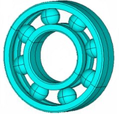
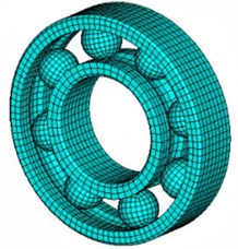
The rolling bearing was generally consisted of four parts such as the rolling element, inner ring, outer ring, and retainer. Its internal movement was very complicated. In order to reduce the calculation resources, the retainer was ignored and the geometric model was shown in Fig. 2(a). The inner ring and outer ring of the bearing have applied self-defined line to generate meshes automatically by sweeping. As the rolling element can’t be divided directly, the adopted method was to averagely segment it into 8 parts with same sizes, and then to divide meshes through the mapping method of the element. In this way, the more uniform meshes can be obtained. Finally, the obtained mesh model of the bearing was shown as Fig. 2(b). It had 10,800 elements and 13,737 nodes.
Fig. 1Flow diagram of coupled vibro-acoustic computation
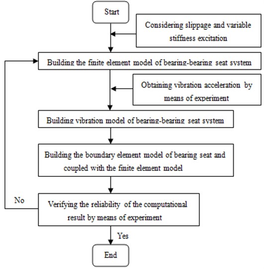
Fig. 2The finite element model of the bearing
a) Geometric model
b) Mesh model
During the simulation of bearing, the relationship between the inner, outer ring and rolling element can be simulated through contact. When the bearing was working, the outer ring was fixed to the bearing seat, and it was therefore defined as the fixed constraint. The inner ring was applied the radial loading of the main axis. In order to reduce the calculation resources, the retainer, aiming at maintaining the distance between rolling elements and prevented them from sliding, was ignored. To achieve the same effect of the retainer, the tangential and axial displacement of rolling element nodes was constrained in cylindrical coordinates, so that the rolling element can only have the displacement in the radial direction. When the bearing was working, the bearing should also be prevented from the axial movement. Therefore, the axial constraint was applied on the nodes of bearing side in rectangular coordinates, so as to avoid the axial movement of the bearing.
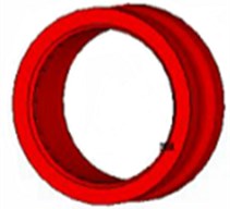
According to the above requirements, the geometric model was divided into meshes in ANSYS software, and the corresponding constraints were also set. As a result, the corresponding calculation results can be obtained, such as the velocity field distribution at 60 ms of the inner ring in Fig. 3(a). As seen from the figure, the bearing was basically in the state of uniform movement, with almost consistent velocity everywhere. In addition, the acceleration field of the inner ring this time was also extracted as Fig. 3(b). As seen from the figure, the force between the bearing and inner ring was relatively large at the marked position with greater acceleration.
Fig. 3Velocity and acceleration distribution of the inner ring for the bearing
a) Velocity field distribution
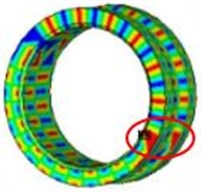
b) Acceleration field distribution
To further observe the effect between the rolling element, inner and outer rings, the stress distribution of the rolling element and outer ring was also extracted as Fig. 4. As can be seen from Fig. 3(b) and Fig. 4(a), there was larger stress in the position of the rolling element where the corresponding position had larger acceleration in the inner ring. And regions where the bearing outer ring contacts with the rolling element also had relatively larger stress.
Fig. 4Stress distribution of the rolling element and bearing outer ring
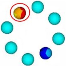
a) Stress distribution of the rolling element
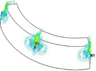
b) Stress distribution of the outer ring
Fig. 5Finite element model of the bearing seat
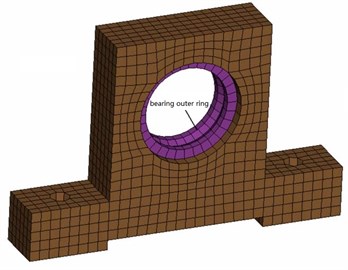
Fig. 6Vibration acceleration of the bearing seat
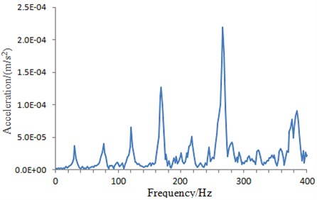
Through the above analysis, the response of the bearing outer ring can be obtained and then mapped to the bearing seat, as shown in Fig. 5. Further, the vibration acceleration at the greater response region on the bearing seat was extracted as Fig. 6.
3.3. Building coupled vibro-acoustic model of bearing
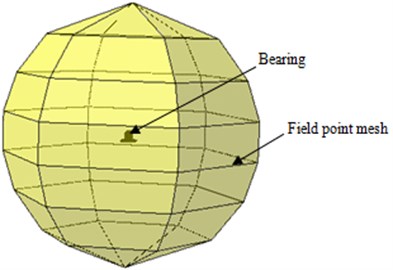
The radiation noise of the bearing seat was simulated by noise analysis software SYSNOISE. The pre-processing for the boundary element model of bearing seat was completed in software ANSA. The external surface of bearing seat was extracted on the basis of finite element model of bearing seat, and the meshes were divided by shell elements to divide the external surface of the bearing seat into shell elements whose shape was consistent with the finite element model and whose element number and node number were one-to-one correspondent with the finite element model. The shell elements were imported to SYSNOISE. The boundary element model of bearing seat was a closed cavity as shown in Fig. 7. Finally, the field mesh should be built to receive the radiation noise, as shown in Fig. 8. The outer sound field of the bearing seat radiation noise was solved by direct boundary element method. In SYSNOISE software, analysis type and air material parameters were set. The normal direction of the meshes was checked. The normal of the boundary element model should be directed at the side where the fluid existed, otherwise, the normal direction of the model should be adjusted. The vibration acceleration of all nodes on the external surface was acquired by extracting the computational results of the bearing seat based on the designed program. It was then applied on boundary element model of bearing seat as boundary conditions.
Fig. 7Boundary element model of the bearing seat
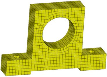
Fig. 8Finally computational model of the bearing seat
4. Verification of simulation model and optimization design
4.1. Model verification
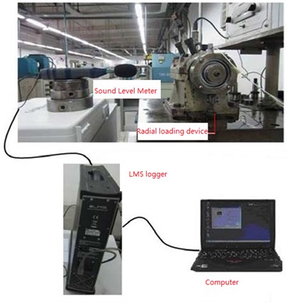
To verify the reliability of the coupled vibro-acoustic model for the bearing seat proposed in this paper, noise test was carried out on the bearing-bearing seat system. Noise test was completed on bearing fatigue test bed which could realize application of bearing rotating speed and radial loading, as shown in Fig. 9. The sound level meter was placed near the bearing seat, and the sound signals gathered were transmitted to LMS logger before transmitting to the computer for storage and analysis.
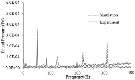
The rotating speed of the tested bearing was set as 1000 r/min, and the computational results of the coupled vibro-acoustic model and test results were compared and analyzed. Comparison and analysis between sound pressure frequency spectra for simulation and experiment was shown in Fig. 10. It can be seen from Fig. 10 that the characteristic frequency of the experimental sound pressure was 50 Hz, while the characteristic frequency of the computational sound pressure was 49.5 Hz, with a difference of 1 %. This indicated that the simulation result was consistent with that of the experimental, which verified the reliability of the coupled vibro-acoustic model proposed in this paper.
Fig. 9Radiation noise test facility of the bearing
In addition, there are indeed some peaks in the computational results, as shown in Fig. 9. In the paper, the rotating shaft is not added in the computational FEM model, which is simulated by the definition of the relationship between the rotating shaft and bearing, such as the rotational speed, contact friction and other parameters. As a precise instrument, the bearing will present defects during the manufacturing process, such as waviness, which is very difficult to be avoided. During the operation of the bearing, more serious fluctuation is appeared in the acceleration of the bearing seat due to the waviness of the bearing, as shown in Fig. 6. It is just verified by the acceleration fluctuation of the bearing seat. Then, the vibration acceleration is imported into FEM model for computing noise, and the radiation noise of the bearing seat can be obtained through this computational model. More peaks existed in the computational results, which can be explained by the following reasons. On one hand, the bearing seat has some modals within the computation frequency, thus generating some resonance peaks. On the other hand, there are many peaks in the acceleration of the bearing seat obtained through experiments, which have greater excitation, thus resulting in higher noise. Therefore, they will finally lead to more peaks in the computational radiation noise.
Fig. 10Comparison of sound pressure between experiment and simulation
4.2. Optimization design
To reduce bearing noise, it was necessary to carry out optimization design of the bearing system. The noise of the characteristic frequency point was very important for the bearing design. As a result, some measures should be taken to reduce the noise. Some researchers indicated that the parameters such as the number of rollers, radial clearance and oil dynamic viscosity were very important to reduce the noise of the bearing. Therefore, we could make some researches in these aspects based on the verified simulation model.
Fig. 11 showed the sound pressure level changes with respect to the number of rollers for various rotational speeds of the inner race.
Fig. 11Sound pressure level changes with respect to the number of rollers
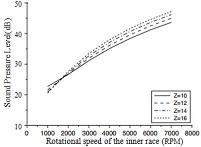
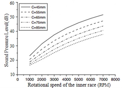
Fig. 12Sound pressure level changes with respect to the radial clearance of the bearing
The results showed that the sound pressure level increased with the number of rollers in general. While the sound pressure level decreased, the number of rollers increased for a low rotational speed of 1000 rpm. In general, the fundamental frequency of the bearing noise increased with an increase in the number of rollers. Thus the sound pressure would be increased due to the high fundamental frequency. However, the distributed rolling contact load of the roller decreased with an increase in the number of rollers. Thus, the sound pressure level of the bearing may then decrease as the number of rollers increases, because of the low oil film pressure generated between the outer ring and rollers. According to the results, the phenomenon occurred at the operational condition of low speed.
The sound pressure level changes with respect to the radial clearance of the bearing were shown in Fig. 12.
The results showed that the sound pressure level decreased with increase of the radial clearance of the bearing, because the pressure generated between the races and the rollers would be decreased as the radial clearance of the bearing increases.
Reference [8] indicated that chaotic response may occur in a bearing when the bearing radial clearance exceeds a certain value. As a result, bearing radiation noise may increase. Therefore, it was necessary to research such case.
According to the research method for chaotic response of a rolling bearing as shown in reference [14], the largest Lyapunov exponent of the bearing could be obtained, as shown in Fig. 13.
It was shown in reference [14] that the bearing was under a stable state operation when the largest Lyapunov exponent was less than 0. On the contrary, chaotic response would occur during operation. It was shown in Fig. 13 that the largest Lyapunov exponent of the bearing in this paper was less than 0 within the whole range of rotating speed, and the bearing was under a stable state operation. It was also shown in Fig. 13 that radiation noise results calculated by the technique were reliable. In the actual engineering, in order to effectively research bearing radiation noise by the coupled vibro-acoustic technique, the largest Lyapunov exponent of the bearing could be firstly calculated in order to determine which rotating speeds and bearing clearances would lead to chaotic response. At this moment, radiation noise of the bearing could be tested only through an experiment. As for bearings under the stable state, radiation noise could be quickly predicted by the coupled vibro-acoustic technique. The mentioned analysis showed that the coupled vibro-acoustic technique mentioned in this paper was very important for low-noise design of bearings.
The sound pressure level changes with respect to the oil viscosity were shown in Fig. 14.
Fig. 13Largest Lyapunov exponent changes with respect to the radial clearance of the bearing
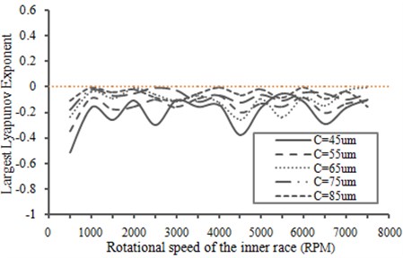
Fig. 14Sound pressure level changes with respect to the oil viscosity
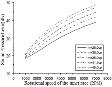
The results showed that the sound pressure level of the bearing increased with the oil viscosity, because the high oil film pressure would be generated as the viscosity increases.
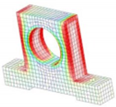
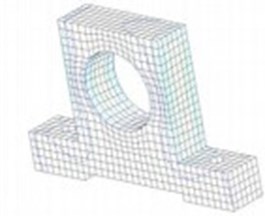
The optimal parameters were chosen to calculate the radiation noise of the bearing and compared with the original one as shown in Fig. 15.
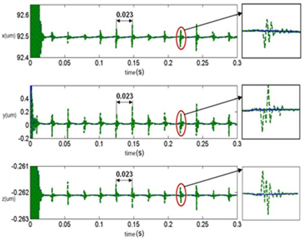
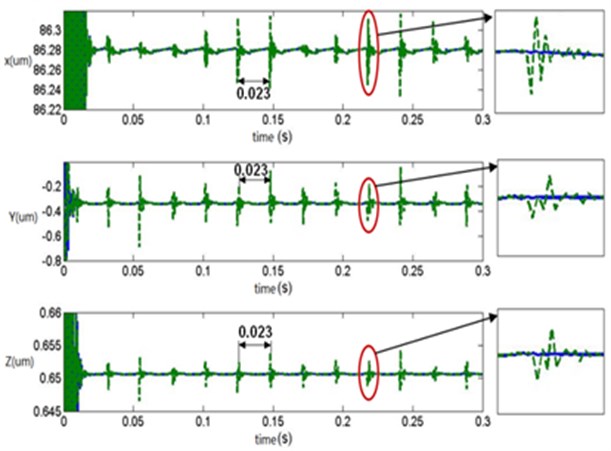
It can be seen from Fig. 15 that the bearing with the optimal parameters would have a lower noise in the characteristic frequency point. In addition, the vibration response of the original and the optimization bearing can be also found in Fig. 16.
Fig. 15Noise comparison between the original and the optimization structure
a) The original result
b) The optimization result
According to Fig. 16, under the radial load of bearing, the displacement response of the bearing seat mainly occurred at X direction, the displacement response at other two directions were small. After optimization, the maximum value at X direction reduced by 40 %, which reached the anticipated result. In addition, the rolling bearing had often defects in manufacturing, such as waviness and surface roughness. They were a kind of form error on the inner and outer ring surface of the rolling bearing. With the improvement of manufacturing technology and accuracy, the influence of surface roughness on the vibration noise of the rolling bearing was decreased gradually, while the influence of waviness was still prominent. Currently, there was no a good way to avoid it. In addition, during rotation of the rolling bearing, the cyclical slippage phenomenon usually appeared. The mentioned defects will lead to the cyclical fluctuations of the displacement for the rolling bearing, as shown in Fig. 16.
Fig. 16Vibration response comparison between the original and the optimization structure
a) Displacement response of the original structure
b) Displacement response of the optimization structure
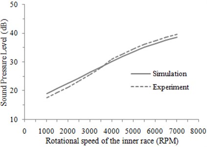
According to the above analysis, it only indicated that there was a certain convenience for designing the rolling bearing by using coupled vibro-acoustic method. However, it was necessary to verify whether the acoustic performance of the finally designed rolling bearing was better than that of the traditional method. Traditionally, the low-noise rolling bearings were designed on the basis of experiments, with their performance improved through the repeated experiment. In this way, the design cycle will be very long, and the design cost will be also high. As learned from the roll bearing manufacturer, it will take six months to design a new bearing by means of the traditional design method. In this paper, the coupled vibro-acoustic method was used to design the rolling bearings, and the design cycle was only one month. In order to verify the rolling bearing performance designed by the proposed method in this paper, its sound pressure level was tested by experiments. And then it was compared with that of the rolling bearings designed by the experimental method, as shown in Fig. 17.
As can be seen from Fig. 17, the sound pressure level of the rolling bearing designed by the proposed method in this paper didn’t much differ from that of the designed by the traditional experimental method. At high rotation speed, the sound pressure level of the rolling bearing designed in the paper was relatively smaller. Therefore, relatively speaking, the proposed design method had some advantages, which can not only save costs and improve efficiency, but also ensure the performance.
Fig. 17Comparison of sound pressure level between two kinds of methods
5. Conclusions
1) In this paper, slippage of the rolling element bearing and its variable stiffness incentive were considered to accomplish the vibration coupling between the bearing and bearing seat as well as the coupling between bearing vibration and noise by means of combination of kinetic model, FEA model and boundary element method, so as to build a perfect coupled vibro-acoustic model of the bearing.
2) The bearing noise experiment was completed by bearing fatigue test bed and LMS logger, which verified the effectiveness of the coupled vibro-acoustic model of the bearing in the paper, thus providing a new thought and method for analyzing and calculating bearing noise, and providing theoretical basis for developing low-noise rolling bearings.
3) Based on the conclusion, an improved rolling bearing was proposed, and its superiority was verified by means of simulation.
4) In order to further verify the superiority of the proposed method in this paper, the designed rolling bearing was compared with that of the traditional design method. The results showed that the proposed design method was reliable.
References
-
Sunnersjo C. S. Varying compliance vibrations of rolling bearings. Journal of Sound and Vibration, Vol. 58, 1978, p. 363-373.
-
Fukata S., Gad E. H., Tamura H. On the radial vibration of ball bearings (computer simulation). Bulletin of the JSME, Vol. 28, 1985, p. 899-904.
-
Mevel B., Guyader J. L. Routes to chaos in ball bearings. Journal of Sound and Vibration, Vol. 162, 1993, p. 471-487.
-
Childs D. W. Fractional frequency rotor motion due to clearance effects. Journal of Engineering Power, Vol. 104, 1982, p. 533-536.
-
Saito S. Calculation of nonlinear unbalance response of horizontal Jeffcott rotors supported by ball bearings with radial clearances. Journal of Vibration, Acoustics, Stress, and Reliability in Design, Vol. 107, 1985, p. 416-420.
-
Lioulios A. N., Antoniadis I. A. Effect of rotational speed fluctuations on the dynamic behaviour of rolling element bearings with radial clearances. International Journal of Mechanical Sciences, Vol. 48, Issue 8, 2006, p. 809-829.
-
Harsha S. P., Sandeep K., Prakash R. The effect of speed of balanced rotor on nonlinear vibrations associated with ball bearings. Mechanical Sciences, Vol. 45, 2003, p. 725-740.
-
Kappaganthu K., Nataraj C. Nonlinear modeling and analysis of a rolling element bearing with a clearance. Communications in Nonlinear Science and Numerical Simulation, Vol. 16, 2011, p. 4134-4145.
-
Sawalhi N., Randall R. B. Simulation gear and bearing interactions in the presence of faults Part I. The combined gear bearing dynamic model and the simulation of localised bearing faults. Mechanical Systems and Signal Processing, Vol. 22, Issue 8, 2008, p. 1924-1951.
-
Ghaisas N. J., Wassgren C. R., Sadeghi F. Cage instabilities in cylindrical roller bearings. Journal of Tribology – Transactions of the ASME, Vol. 126, Issue 4, 2004, p. 681-689.
-
Spiegelberg C., Björklund S. F., Andersson S. Simulation of transient friction of a cylinder between two planes. Wear, Vol. 254, Issue 11, 2003, p. 1170-1179.
-
Wikiel B., Hill J. M. Stick-slip motion for two coupled masses with side friction. International Journal of Non-Linear Mechanics, Vol. 35, Issue 6, 2000, p. 953-962.
-
Shao Y. M., Wang P., Chen Z. G. Effect of waviness on vibration and acoustic features of rolling element bearing. Proceedings of the ASME 2012 International Design Engineering Technical Conferences and Computers and Information in Engineering Conference, 2012, p. 70817.
-
Li C., Zheng J. R. Study on chaos behavior of flexible rotor rolling bearing system. China Mechanical Engineering, Vol. 25, Issue 3, 2014, p. 393-398.
