Abstract
This paper presents a technique for minimizing vibrations of the steering wheel from vibration transmission path based on the method of shift frequency vibration reduction. At first, a road experiment was conducted on a vehicle with brake judder. Transmission path and excitation frequency of the vibration were determined through analyzing the experimental data. Then, modal analysis on the whole structure of the steering wheel was carried out by the finite element method. In this way, its inherent frequencies and modes could be obtained. In order to verify the accuracy of the finite element model, the modal experiment was carried out and its results were compared with the simulated one. Sensitivity analysis and optimization design were carried out on the fixation support of the steering wheel by using Optistruct in Hyperworks. In this way, the inherent frequency of the whole structure could avoid the excitation frequency. Finally, an experimental verification was also carried out on the vehicle, and the results show that the vibration acceleration value of the steering wheel reached the allowable value. The technique for minimizing vibrations of the steering wheel is feasible in this paper.
1. Introduction
Brake judder referred to the violent vibration of the steering wheel, cab, vehicle body, brake pedal and seat when the vehicle was braked within a certain speed [1]. Brake judder was a kind of low frequency vibration. Fluctuation of braking torque was the excitation source of vibration. For a drum brake, braking torque was generated by the mutual contact between a brake shoe friction disk and a brake drum. Fluctuation of braking torque would exist when any of contact area, contact pressure, friction coefficient and equivalent radius was changed [2-5]. Then, fluctuation of braking torque was transmitted to the steering wheel and cab through the middle structures. As a result, both of them would generate judder. Worse still, a driver would feel “hand judder” at the steering wheel, which would greatly affect comfort and safety in ride.
At present, researchers have conducted many researches about mechanism and vibration transmission path of brake judder. The following relationship existed between the excitation frequency and vehicle speed:
where, was the excitation frequency. was the rotation speed of the wheel. was orders, and the main order was the second order [6-12].
However, a few papers researched how to reduce brake judder. In the market, reducing brake judder was commonly realized by replacing the brake and steering gear. Except for the high cost, these measures were not always effective. Therefore, a lot of economic losses might be brought to the company. The paper adopts shift frequency vibration reduction to change the inherent frequency of the whole structure for the steering wheel, and then vibration reduction can be realized. In addition, feasibility of the method is verified by a road experiment.
2. Experiment and analysis of the steering system
2.1. Experiment scheme
A road experiment was conducted to determine vibration transmission path and excitation frequency during braking. A vehicle with brake judder, which was produced by a company, was taken as the experimental object. Before the experiment, whether air pressure and dynamic balance of tires could satisfy the experimental requirement was checked. The experimental place was set on a flat, straight and dry highway. Such pavement was deemed to be Class B pavement. The experiment was conducted in a sunny day, and wind speed was not higher than 5 m/s. Temperature was between 15 °C and 25 °C.
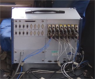
The experimental scheme was shown in the following. 1) Acceleration sensors were installed at the steering wheel, cab, steering drag link as shown in Table 1. 2) The brake was slightly slammed during braking, and the initial speeds were 40 km/h, 50 km/h, 60 km/h and 70 km/h, respectively. 10 sets of data were collected under each speed. 3) Sampling frequency was 512 Hz, and each sampling time was at least 50 s. PCB acceleration sensors and a DEWETRON data collection system were used as the experimental instrument as shown in Fig. 1 and Fig. 2, respectively.
Table 1The detailed layout of acceleration sensors
Location | Direction |
Steering wheel | , , |
Top and bottom of cab | , , |
Steering drag link | , , |
Steering knuckle arm | , , |
Plate spring | , |
Frame | , , |
Left side of axle | , |
Cab suspension | , |
Fig. 1Measuring points of acceleration sensors on the steering wheel
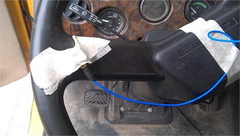
Fig. 2DEWETRON data collection system with 24-channel
2.2. Processing and analysis of the experimental data
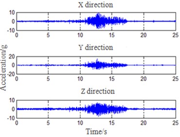
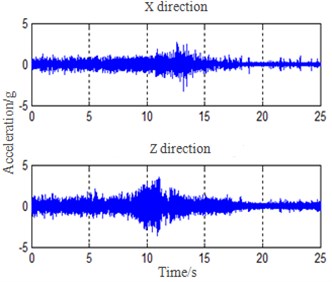
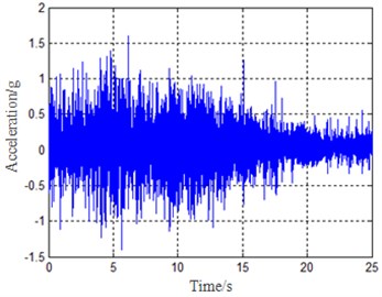
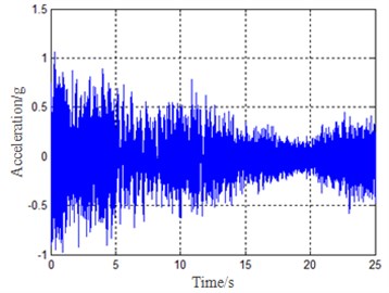
Firstly, smoothness and filtration were carried out on the collected vibration data. Fourier transformation and frequency spectrum analysis were conducted for the processed data. Data in the collection system was exported and processed by Matlab software. Diagrams of the time domain and frequency domain were shown in Fig. 3 and Fig. 4, respectively.
Fig. 3Time domain diagram of each measuring point
a) Diagram of air pressure
b) Diagram of vibration acceleration for the steering wheel and vehicle speed
c) Vibration acceleration of the steering wheel in 3 directions
d) Vibration acceleration of the steering knuckle arm
e) Vibration acceleration of the plate spring in direction
f) Vibration acceleration of cab suspension in direction
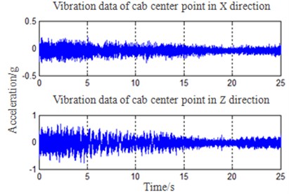
g) Vibration acceleration of cab
Fig. 4Spectrum of several measuring points
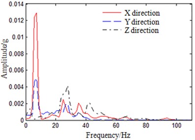
a) Auto-power spectrum of the steering wheel in 3 directions
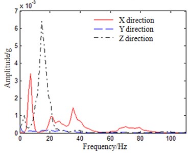
b) Auto-power spectrum of the steering knuckle arm
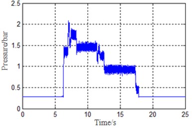
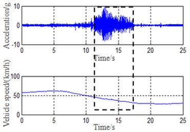
Fluctuation of air pressure in Fig. 3(a) reflected the fluctuation of braking torque during braking process. The braking torque fluctuation was mainly caused by the uneven contact face between brake drum and brake shoe. Such fluctuation was the excitation source of vibration, and the experimental results were consistent with the published paper [2]. Fig. 3(b) showed that the steering wheel judder during braking appeared within 30 km/h-47 km/h. Judder was most serious under vehicle speed of 41 km/h, and the corresponding frequency was 3.56 Hz at this moment. It was shown from Fig. 3(c) to Fig. 3(g) that the acceleration amplitude of cab was already very small when vibration of brake was transmitted from plate spring, frame and suspension to cab. However, vibration acceleration amplitude of the steering wheel was obviously magnified when vibration of brake was transmitted from the steering knuckle arm, steering drag link and steering gear to the steering wheel. Meanwhile, the correlation function analysis was conducted to vibration data. Results showed that correlation coefficients from brake to the steering drag link and steering wheel were both over 0.75. Therefore, the major transmission paths of vibration during braking were obtained as following. 1) Brake (fluctuation of braking torque) → plate spring → frame → cab suspension → cab. 2) Brake (fluctuation of braking torque) → steering knuckle arm → steering drag link → steering gear → steering wheel. In addition, the acceleration root mean square value of cab was 0.123 g and it was within the allowable value (the allowable value was 0.37 g). The acceleration root mean square value of the steering wheel in the direction was 1.188 g, which was obviously more than the allowable value. As a result, a driver could obviously feel “hand judder” at the steering wheel. Therefore, the vibration transmission path which was from brake to the steering wheel was mainly taken into account, and some measures were taken to reduce the vibration.
It was shown in Fig. 4(a) that components of vibration frequency for the steering wheel were mainly 7.23 Hz and 26.12 Hz. In addition, Fig. 4(b) showed that components of vibration frequency for the steering knuckle arm were mainly 7.23 Hz and 14.84 Hz. It was shown in Eq. (1) that when num was 2, 4 and 7, the calculated frequencies were exactly close to 7.23 Hz, 14.84 Hz and 26.12 Hz. In addition, the experimental results were consistent with the relevant research [1, 11, 12].
According to the mentioned analysis, the major transmission path which caused the steering wheel vibration during braking was shown in the following. Brake (fluctuation of braking torque) → steering knuckle arm → steering drag link → steering gear → steering wheel. The excitation frequencies were the second, fourth and seventh orders in Eq. (1). The serious judder was generated in the steering wheel mainly due to resonance between excitation frequencies and the inherent frequencies of the steering wheel. It was expensive to realize vibration reduction from sources by changing materials and structures of brake shoe and brake drum. Therefore, it was necessary to change the inherent frequencies of the steering system from vibration transmission path to avoid excitation frequencies and reduce vibration. Due to the serious vibration of the steering wheel, it would have an effect on the steering system. As a result, the steering system which was made of the steering wheel, steering column, universal joint, fixation support and other structures was selected as the analysis object. Its inherent frequencies were solved through the finite element method. Then, the constrained modals of the steering system were tested to verify accuracy of the finite element model for guaranteeing the subsequent analysis. And finally, optimization design of the steering system was conducted based on the finite element model.
3. Modal analysis of the steering system
According to the mentioned analysis, the serious vibration appeared at the steering wheel during braking, and it was because excitation frequencies and the inherent frequencies of the steering system were close. As a result, resonance was caused to magnify the vibration. Therefore, modal analysis on the steering system was carried out by the finite element method. The model was simplified appropriately. The processed finite element model was shown in Fig. 5. The whole model had 153,979 nodes and 351,230 elements. Constraints were applied according to the actual states of the steering system in vehicle, and then, modals were calculated.
During building the finite element model, a few simplifications were conducted to the steering system, which may cause the difference between the finite element model and the actual structures. Therefore, it was necessary to conduct a constrained modal experiment to verify the reliability of the finite element model.
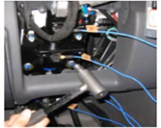
During our experiment, the hammer was used to hit the steering system to test acceleration responses of measuring points, and modal parameters were extracted. Arrangement of measuring points and excitation locations were shown in Fig. 6. In order to test modals of the steering system in each direction, excitation should be conducted in both and directions, respectively.
Fig. 5Finite element model of the steering system
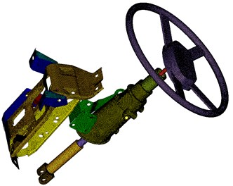
Fig. 6Arrangement of measuring points and excitation locations
Modal frequencies and modes of the steering system at top 6 orders under the constrained state were shown in Table 2. It was clear that the inherent frequencies of the finite element model and the experiment did not differ much and were both within the allowable value (the allowable value was about 5 %). Therefore, the finite element model was reliable and could be used in the subsequent analysis.
According to the method of modal superposition, vibrations of the system were mainly superimposed by the top of several order modals. Therefore, modals of the steering system at the top 6 orders were solved as shown in Fig. 7.
It was shown in modal analysis that the inherent frequency of the first order modal was exactly close to excitation frequency of 26.12 Hz. In addition, the steering system juddered in left-right direction during braking. As a result, the serious judder of the steering system was caused by resonance, and such result showed that the mentioned analysis results were reliable. The inherent frequency solved by simulation was very close to the result in the experimental one, which may verify the reliability of the simulation results.
Fig. 7Top 6 order modals of the steering system
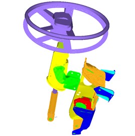
a) The first order modal
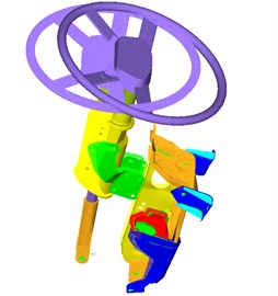
b) The second order modal
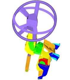
c) The third order modal
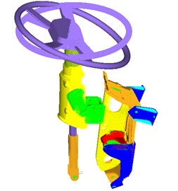
d) The fourth order modal
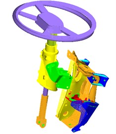
e) The fifth order modal
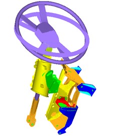
f) The sixth order modal
4. Optimization design and experimental verification of the steering system
In order to reduce vibration of the steering system, the inherent frequencies of the steering system was changed to avoid resonance. The fixation support of the steering system was made of over 10 welded sheets, and modification could then be realized easily. Therefore, the inherent frequencies of the whole structure was changed by changing thickness of steel plates in the steering system fixation support. Optistruct in Hyperworks was applied to optimize the steering system. Thicknesses of steel plates in fixation support were taken as design variables, maximization of the first order inherent frequency of the steering system was taken as the objective function, and the total mass of the fixation support was taken as a constraint function.
Firstly, sensitivity analysis was conducted to solve the sensitivity coefficients of all the steel plates to the first order inherent frequency. The finite element model of the fixation support and No. of each steel plate were shown in Fig. 8. Sensitivity coefficient of each steel plate was shown in Table 3.
Table 2The detailed description of the top 6 order modals
Order | Experiment / Hz | Simulation / Hz | Relative Error / % | Mode |
1 | 25.13 | 25.24 | 0.43 | Left-right vibration |
2 | 40.05 | 41.57 | 3.80 | Front-rear vibration |
3 | 85.59 | 84.42 | –1.36 | Rotation around axis |
4 | 95.41 | 93.35 | –2.16 | Rotation around axis |
5 | 122.23 | 124.54 | 1.89 | Side-to-side vibration of fixation support |
6 | 148.87 | 146.95 | –1.29 | Rotation of steering wheel around axis, along with front-and-rear vibrations of fixation support |
Fig. 8Finite element model and No. of each steel plate
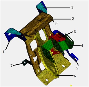
According to Table 3, thicknesses of steel plates 2, 4, 5 and 6 had a relatively large effect on the first order inherent frequency. Therefore, thicknesses of these steel plates were taken as design variables. Upper and lower limit values of the design variables were shown in Table 4.
Table 3Sensitivity coefficients of each steel plate
No. | Sensitivity coefficient |
1 | 0.0013 |
2 | 2.754 |
3 | 0.183 |
4 | 1.324 |
5 | 0.735 |
6 | 1.754 |
7 | 0.0014 |
8 | 0.0057 |
Table 4Upper and lower limit values of design variables
Variable / mm | Initial value | Lower limit value | Upper limit value |
2.0 | 1.5 | 2.5 | |
3.0 | 2.5 | 3.5 | |
2.5 | 2.0 | 3.0 | |
2.0 | 1.5 | 2.5 |
After defining design variables, the objective of optimization design should be set. In this paper, maximization of the first-order inherent frequency was taken as the objective function. In addition, in order to avoid mass increase of the steering system during optimization design, the constraint function was that mass of the steering system should be less than 13.8 kg. Finally, the optimized results were shown in Table 5.
Table 5Comparison of results before and after optimization
Parameter | Initial value | Optimized value |
/ mm | 2.0 | 2.3 |
/ mm | 3.0 | 2.5 |
/ mm | 2.5 | 2.1 |
/ mm | 2.0 | 2.4 |
First order frequency / Hz | 25.24 | 29.62 |
Total mass / kg | 13.8 | 12.9 |
According to Table 5, the first order inherent frequency of the steering system increased by 4.38 Hz, which was 3.5 Hz higher than the excitation frequency, and realized the goal of 3 Hz increments [13]. Moreover, the total mass also decreased by 0.9 kg after optimization, and the goal of lightweight was achieved. Thus, the optimization design has a prominent effect.
An experiment was conducted in the improved vehicle. It was shown in the experimental results that vibrations of the steering system were obviously reduced during braking, and the feeling of “hand judder” disappeared. Acceleration values before and after optimization were shown in Table 6.
Table 6Acceleration values of the steering system before and after optimization
Direction | Initial value / g | Optimization value / g |
1.188 | 0.3125 | |
0.8674 | 0.3011 | |
0.9673 | 0.3142 |
It was shown through comparison that vibration acceleration at the steering system was obviously reduced after the optimization. Such value was within the allowable scope, and the goal of vibration reduction was achieved. Meanwhile, such result also demonstrated that it was feasible to avoid resonance by changing the inherent frequencies of the steering system based on vibration transmission path.
5. Conclusions
This paper presents a technique for minimizing vibrations of the steering wheel from vibration transmission path based on the method of shift frequency vibration reduction. The inherent frequencies of the steering system are changed to avoid resonance, so as to realize the goal of vibration reduction. Simulation analysis and road experiment are both conducted to verify the effectiveness of this method. Meanwhile, this research method also provides some references for the other similar structures in vibration reduction. In comparison with changing the structure of brake to reduce vibration source, such vibration reduction measures based on vibration transmission path are much cheaper. This method has high application value in engineering.
References
-
Gao X. J., Yu Z. P., Zhao L. J. An analysis on transmission path from brake judder to steering wheel vibration. Automotive Engineering, Vol. 28, Issue 3, 2006, p. 267-270.
-
Yao G. J., Li W. P. The review of drum brake judder. Mechanical Design, Vol. 27, Issue 11, 2010, p. 1-4.
-
Jacobsson H. Aspects of disc judder. Proceeding of the Institution of Mechanical Engineers, Journal of Automobile Engineering, Vol. 217D, 2003, p. 419-430.
-
Kim M. G., Ho-II J., Wan S. Y. Sensitivity analysis of chassis system to improve shimmy and brake judder vibration on steering wheel. SAE Technical Paper, No. 960734, 1996.
-
Meyer R. Brake judder-analysis of the excitation and transmission mechanism within the coupled system brake, chassis and steering system. SAE Technical Paper, No. 2005-01-3916, 2005.
-
Duan C., Singh R. Analysis of the vehicle brake judder problem by employing a simplified source-path-receiver model. Proceedings of the Institution of Mechanical Engineers, Journal of Automobile Engineering, Vol. 225D, Issue 2, 2011, p. 141-149.
-
Han J. R. Research on Brake Judder of Automotive. Nanjing University of Aeronautics and Astronautics, Nanjing, 2008.
-
Ma M. C. Research on Experiment and Control of Brake Judder for Automotive. South China University of Technology, Guangzhou, 2011.
-
Zhang H. J., Gu Z. Q., Yang Y., et al. Analysis and improvement of low-frequency vibration of drum brake. Automotive Engineering, Vol. 31, Issue 11, 2009, p. 1060-1065.
-
Pang H., Fang Z. D., Li H. Y., et al. Test analysis on cab jitter response induced by braking force. Journal of Vibration and Shock, Vol. 31, Issue 15, 2012, p. 146-149.
-
Zhang L. J., Ning G. B., Yin D. X., et al. Experimental study on the transfer path of steering wheel vibration caused by brake torque fluctuation. Journal of Vibration and Shock, Vol. 25, Issue 2, 2006, p. 70-74.
-
Ning G. B., Zhang L. J., Yin D. X., et al. Experimental research on the vehicle steering wheel wobbling induced by brake judder. Chinese Journal of Construction Machinery, Vol. 2, Issue 3, 2004, p. 355-359.
-
Wang J. W. CAE Analysis and Test Research of a SUV Steering System Vibration. South China University of Technology, Guangzhou, 2013.
About this article
This work was supported by the Fundamental Research Funds for the Central Universities (2015QNB10).
