Abstract
In the article the construction of the test bench for the durability test of the friction couplings was showed. The properties of the tested tribological pairs are fully described, i.e. chemical constitution, kind of material and the results of the surface topography tests of basic material and with lubricant micropockets. The methodology and scope of the preliminary tests, including observation of course of changes in vibration signals on the housing of the pin-on-disc tester, for different load values and tribological couplings, i.e. with textured or non-textured surface. The vibroacustic research was carried out with industrial unit CSI 2130 by Emerson and with vibration sensor A0760GP. Comparative analysis of vibration signals and amplitude-frequency spectrums was performed for chosen work conditions of the tribological pair. Finally, the possibility to use the measurement of vibration signal to predict a seizure of the tribological pair was described and directions for further research were given.
1. Experimental details of the vibration signals research
The measurements of the vibration signals was performer with the testing stand propelled by high power electric motor combined with the 12 speed gearbox. That tester was chosen since its usefulness and availability for the durability tests, but it was also selected with the full knowledge the construction of the test stand could be a source of essential instability of vibration signal measurements (gears in the gearbox could be a source of their own vibration signal, transmitted through the test stand body and mixed with the other vibration signal disturbances and with the signal from the tested coupling).
As it was technical impossible to identify the vibration signal disturbances from the tested bearing signal and therefore the spectrum analysis was mainly carried out observing the differences in the research of the tested couplings under differed load values. Signal of the tested bearing and its changes for increasing load. However, at this stage of the study, the observed changes in the vibration signal were not analyzed to find out what was the direct cause of the achieved differences, leaving this issue for any further research.
The simplified scheme of the test stand is showed in the Fig. 1 achieved differences, leaving this issue for any further research. The simplified scheme of the test stand is showed in the Fig. 1.
Plain sliding rings sr were fixed rigidly on the horizontal base of the test stand. The rings were made of the same material, i.e. 100CrMnSi6-4 bearing steel, volume hardened (hardness of 60 HRC), finished to the identical surface roughness Ra ~0.16 µm, but one of the rings made by laser texturing surface method lubricant micropockets [1, 2], filled with mineral bearing lithium grease ŁT-43 produced. Two roller shaped identical counterparts sliding on the surface of the tested rings had the similar hardness and surface roughness as the rings. The rollers were fixed in a holder propelled by power unit at the rotational speed of 500 rpm. Pressure on the surface was within the range of 13 MPa to.
The measurements were performed with equipment Emerson CSI 2130 combined with unidirectional accelerometer A0760GP. The sensor was fixed with permanent magnet to the tested ring and vibration acceleration in a surface perpendicular to the ring was measured.
Among the possible settings of the instrument to implement fast Fourier transform (FFT) of the recorded signal it was decided to collect spectrums with a step of 025 Hz and in the range of 0-1.6 kHz (the fw value is the 33 spectral line).
Fig. 1The scheme of the test stand: m – electric motor, gb – gearbox, y – holder, c – roller, sr – sliding ring, b – base, as – acceleration sensor, sra – recorder and signal analyzer, F – load acting on the rollers and the rings surface
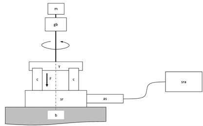
During each test the signals were recorded after 5 seconds from the power unit startup (time needed to stabilize the rotational velocity in the coupling) and under first load, than after 30 seconds under higher load and finally after 10 minutes of continuous operation of the coupling under higher load (the results of the durability tests described in showed it was the time of running-in process). For each kind of test conditions) a vibration signal was recorded three times and their amplitude spectra were completed. As it was revealed they were comparable.
In the Fig. 2 chosen examples of the recorded signals are presented. It is clearly seen that vibration signals consist of a whole range of components of the strongest in the considered frequency range is the component of frequency about 699 Hz. The other frequency values are also detected about 150, 275, 349, 998, 1040, 1098, 1148, 1281, 1397 (≈2.699), 1447 and 1498 Hz. Nevertheless, at this stage of the study the observed frequencies were interpreted as disturbances of a signal from power unit, as with the tested coupling evidently could be associated only small components of frequency about 8.25, 16.5 and 24.75, being three harmonic frequencies of the holder with the rollers (fw).
Fig. 2Comparison of achieved signal spectrums recorded at the test stand: for lower load (upper line) and higher load (middle line) of the coupling after startup and for the coupling after 10 minute operation under higher load (bottom line) – the ring without lubricant micropockets (left column) and the ring with lubricant micropockets (right column)
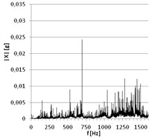
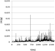
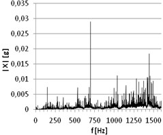
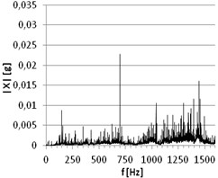
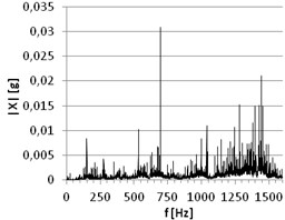
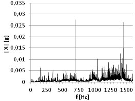
At this stage of the preliminary program the recognized differences between spectrums could be described as: – the presence of the strong component of a frequency about 523.25 Hz in the spectrums recorded only from the signals of the sliding ring without lubricant micropockets (dry lubrication mechanism within the coupling), – the presence of the clear component of a frequency about 424 Hz in the spectrums recorded only from the signals of the sliding ring with lubricant micropockets under higher load, – the presence of the weak component of a frequency about 1447 Hz in the spectrums recorded only from the signals of the sliding ring without lubricant micropockets under lower load.
2. Conclusions
1) The presented test stand, useful to perform tribological durability test, was not fully valuable to complete the research of vibration signals of the tested couplings, as the presence of meaningful disturbances generated by power unit.
2) The achieved variations between vibration signals recorded for the rings with and without micropockets should be confirmed at the test stand more suitable to vibration signal measurements. But after all the results showed the possibility to recognize the couplings with or without grease microspheres on their surface.
3) Change of the counterpart from a pin surface contact to line contact (side surface of the roller) allowed to increase the pressure in the tribological pair even up to 500 MPa and consequently to intensify the friction processes until the seizure of the mating elements. That vibroacustic signals were recorded with industrial unit CSI 2130 by Emerson.
4) The vibration diagnostics tests of the friction couplings (pin-on-disc or ball-on-disc), with or without lubricant micropockets, requires to use low noise power unit, enabling to eliminate additional vibrations of tribological system and enhancing testing capabilities of the stand.
References
-
Napadłek W. Analysis of tribological processes in components of massive roller bearings. Solid State Phenomena, Vols. 220-221, 2015, p. 319-323.
-
Napadlek W. Influence Environment and Parameters Ablative Laser texturing on Selected Properties Surface Layer Steel100CrMnSi6-4. Advanced Material Research, Vol. 874, 2014, p. 17-22.
-
Boruta G. Data diagnostics analysis comprised in the vibroacustic signal of regulation piston engine parameters. Doctoral thesis, Technical University of Poznan, Poznań, Poland, 2006, (in Polish).
-
Machine Condition Monitoring. Brochure BR0267-13, Bruel & Kjaer, Naerum 1989.
About this article
Scientific work financed by the National Centre for Research and Development as the research project No. PBS1/B5/1/2012.
