Abstract
The dynamic response of lined tunnels with a uniform box-type cross-section buried into elastic half-space to explosion seismic waves is studied by employing the matrix force method and treating the structure as a connecting rod system interacting with foundation. The main equations for dynamic analyzing of the hyperstatic structure are deduced and solving method is proposed. A case study is implemented to investigate the influence of span-height ratio of the structure and foundation-structure wave impedance ratio. The results are presented in nondimensional form to obtain a clear physical understanding of the dynamic response of structure. It is shown that the dynamic response of box-type structure can be significantly influenced by the span-height ratio as well as the foundation conditions. Since nondimensional parameters are adopted, the results are independent of dimension and can extend to structures with different size and working conditions. This study provides an analysis method and new insights into the dynamic response of underground box-type structures.
1. Introduction
Box-type structure is wildly used structure type in urban underground space. Generally, these underground structures are designed for civil air defense purpose as well as their economic or social functions. Serving as shelters, the structures must endure the impact of explosions and maintain its stability in case of military strike or terrorist attack. Thus, the investigation of the dynamic response of these structures to explosion seismic waves is of great importance for safety considerations.
In the resent years, the dynamic response of underground structures to explosion seismic wave has been investigated intensively, by model tests [1, 2], theoretical analysis [3-6] and numerical methods [7-9]. The analysis method of dynamic response of underground structure to impact loads has been developed for decades. There are mainly two classes of methods. The first class is elastic dynamic method, in which the underground structure is regarded as a reinforcement of hole buried in infinite elastic or elastic-plastic medium and the wave or stress field is solved for the whole system. These methods suit for the dynamic response analysis of circular lining to plane harmonic wave or step wave. However, they are not very appropriate for structure with complex geometrical shape or impact loading conditions. The other class is structural dynamic methods, in which the surrounding medium is equivalently substituted by the action of spring and damping and the structural dynamic response is solved by the basic physical equations. The difficulty of this class method is how to define the interaction of structure and surrounding medium.
The matrix force method is a classic semi-analytical method, and is employed in the analysis of the dynamic response of underground tunnels by many researches [10, 11]. The method has been validated by comparative studies and the results show that the matrix force method gives a safer design with an acceptable deviation.
In this paper, dynamic response of underground box-type structure to explosion seismic wave is investigated by matrix force method, which belongs to structural dynamic method. The semi-analytical analysis method is detailed introduced and a case study is carried out to reveal the influence of several important factors. This study provides new and interesting insights into the dynamic response of underground box-type structures to explosion seismic waves.
2. Method of analysis
2.1. Basic assumptions
The studied structure is underground box-type structure with a certain cross section and infinite longitudinal extension, as shown in Fig. 1.
Fig. 1Sketch map of underground box-type structure
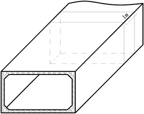
a) Real structure
b) Cross section
The explosive seismic waves induced by underground or surface explosion propagate in rock and soil medium and finally act on the buried structures, exciting the dynamic response. In order to simplify the problem, the explosion seismic wave is assumed to be plane wave, with known wave form, amplitude, and attenuation curve. The surrounding medium is described by elastic half-space model, and the foundation resistance is determined by theory of elastic foundation beam.
Comparative study [12] indicated that planar assumption can provide reasonably results and many literatures adopted the assumption, especilly in analytical and semi-analytical analysises [4-6, 10, 11].
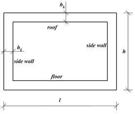
Under the action of vertical loading, the roof of the lining moves toward the excavation and forms debonding region. The interaction between structure and foundation is shown in Fig. 2(a). The structure is hyperstatic. Cut the midpoint of roof, fixed the midpoint of floor and remove the other redundant forces, a basic structure can be obtained, as shown in Fig. 2(b).
Fig. 2The sketch map of studied structure and its basic structure
a)
b)
2.2. Basic equations
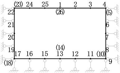
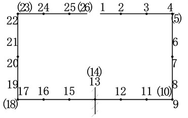
In order to establish basic equations of the dynamic problem, the structure should be discretized into beams and mass points. Considering the efficiency and accuracy comprehensively, the structure is discretized into 17 mass points and corresponding beams. Each mass point has two DOFs (degree of freedom).
For each DOF, the dynamic equivalent equation must be met:
in which: , and stand for inertia force, damping resistance and elastic force, and is the equivalent dynamic loading acting on the mass point.
For the whole structure, the dynamic equivalent equation can be expressed as:
in which: is the mass matrix, is the damping coefficients matrix, is the flexibility matrix, , and are the acceleration velocity, velocity and displacement, respectively.
Eq. (2) can be rewritten as:
2.3. Solving method
2.3.1. Canonical equation
According to the deformation compatibility condition, the deformation of basic structure under the action of loading and redundant force must agree with the deformation of hyperstatic structure. Thus, the canonical equation of force method can be established:
in which:
is matrix of coefficients, which is defined as the flexibility matrix of redundant forces. The matrix describes the relationship between the redundant force and the displacement of point redundant force acting. Element stands for unit displacement. According to reciprocal displacement theorem, . Thus, matrix is symmetric.
is the matrix of free term, which is defined as the flexibility matrix of the external load. The matrix describes the relationship between the external load and the displacement of point redundant force acting.
is the matrix of unknowns, including the 16 unknown forces corresponding to the chain poles supporting the side wall and floor, the 2 unknown forces acting on the cut midpoint of roof, and the 3 unknown forces acting on the fixed midpoint of floor.
2.3.2. The coefficients matrix and the free term matrix
When determining the displacement of basic structure induced by redundant forces, the deformation of structure and the deformation of foundation must be taken into consideration. Virtual power principle is adopted in determining the structure displacement induced by unit force. Applying virtual work principle, the expression of coefficients matrix and free term matrix can be deduced as follow:
in which:
, , stand for the transformation matrix of unit redundant force and internal force (moment , axial force and shear force ) of element. In other words, , , are the internal force matrix when unit redundant force acting on the structure.
, , stand for the transformation matrix of unit external load and internal force of element. In other words, , , are the internal force matrix when unit external load acting on the structure.
, , stand for the combination of flexibility matrix when take flexural deformation, shear deformation and axial deformation into consideration separately. All of them are symmetric belt type squares.
is transformation matrix of unit redundant force and elastic resistance of surrounding rock mass. is transformation matrix of unit external load and elastic resistance of surrounding rock mass.
In Eq. (6) and Eq. (7), the first three terms of coefficients matrix and free term matrix stand for the deformation of structure induced by internal force, in the meanwhile, the last terms stand for the deformation of elastic foundation.
2.3.3. The flexibility matrix
The flexibility matrix of the whole structure, also known as unit displacement matrix, can be determined as follow:
in which: , and are unit internal force matrix of the structural elements, is the unit displacement matrix of the fixed midpoint of structure.
2.3.4. Damping matrix
The damping matrix of real structure is simplified by applying Rayleigh’s damping theory [13], and described by linear superposition of mass matrix and stiffness.
2.3.5. The dynamic parameters of structure
The unit internal force matrixes of elements can expressed as follow:
After the determination of , the dynamic parameters of structures, including displacement , velocity and acceleration , can be solved by programming. In this paper, four order Runge-Kutta method is adopted in solving Eq. (3). The dynamic internal forces then can be determined as follow:
The stresses of the lining structure are thus determined:
in which: and are normal stress and shear stress; is the inertia moment of the lining cross section to the neutral axis; and are the width and thickness of the cross section of lining structure.
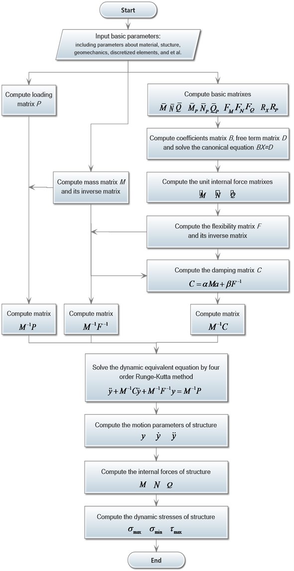
3. Programing and solving
3.1. The order reduction of dynamic equivalent equation
Variable substitution can be applied to reduce the order of the two order dynamic equivalent equation.
Eq. (3) can transforms into the following form by multiple :
And then we obtain:
Let , and then there is .
Let , , , and then the original two order dynamic equivalent equation is transformed into a standard form:
3.2. The flow chart of program
The solving program consists of a main program and a subprogram. The flow chart of the subprogram program is shown in Fig. 3.
4. Case study
4.1. The parameters of studied example
A real underground box-type structure is studied to verify the analysis method and investigate the influence of parameters of structure and impact. The sketch map of the studied structure is shown as Fig. 1(b). The geometrical parameters of structure are listed in Table 1.
Table 1The geometrical parameters of structure
Outer contour | Inner contour | Thickness | ||||
Span | Height | Span | Height | Roof | Floor | Side wall |
5.2 m | 3.6 m | 4.0 m | 2.2 m | 0.8 m | 0.6 m | 0.6 m |
The impact loading is implemented by method recommended by Gerogiadis and et al [14], and regarded as a triangle pulse with certain pressure rising time. In the studied case, the pressure rising time is 28.1 ms, the duration of positive pressure is 300 ms, and the peak load is 3.02×10⁵ Pa.
Fig. 3The flow chart of subprogram
The parameters of structure materials and foundation are listed in Table 2.
Analysis indicates that calculated results by the presented method agree well with the existing insight into the dynamic response of box-type structure. Indexes include vertical displacement of the midpoint of roof, the internal forces and stresses of structure.
Table 2The parameters of structure and foundation materials
Elastic modulus (GPa) | Poisson’s ratio | Specific gravity (kN/m3) | |
Structural material | 37.8 | 0.20 | 25 |
Foundation | 0.85-27.7 | 0.42 | 19.5 |
4.2. Nondimensionalization of parameters
The specific analysis results of a studied case only have a limited reference value for very similar structures. In order to get insights into the influence of several important factors, span-height ratio (S/H) of structure, wave impedance ratio of foundation and structure, are chosen and nondimensionalized. The data range of nondimensionalized parameters are listed in Table 3.
The results also expressed in non-dimensional form. Nondimensional time is defined as the ratio of real time to pressure rising time. Displacement and internal forces are nondimensionalized by dividing them by corresponding physical quantity in static loading condition.
Table 3The parameters’ values of studied working conditions
Working conditions | Span-height ratio | Foundation-structure wave impedance ratio |
1 | 1.0-2.0 | 0.97 |
2 | 1.5 | 0.17-0.97 |
4.3. Results and analysis
4.3.1. The influence of span-height ratio
The analysis results about span-height ratio are shown in Fig. 4. In Fig. 4 and hereafter, the nondimensional time is defined as the ratio betwwen the real timen and the rising time of impact loading. And the nondimensional displacement is defined as the dynamic coefficient.
Fig. 4(a)-(d) indicate that, as the span-height ratio increases, the displacement, moment, axial force and maximum stress of roof increase, the peak value delay, and the vibration frequency decrease. When the span-height ratio increases from 1.0 to 2.0, the displacement and moment of the midsection of roof increase by several times. In the meantime, the axial force and maximum stress increase slightly. From Fig. 4(e)-(f), we can see that the increasing of span-height ratio apparently influence the moment and axial force of side wall. The moment of the midsection of side wall increase by over ten times, and the maximum axial force changes from positive (tension) to negative (compression). The vertical displacement of floor also increases apparently along with the increasing of span-height ratio, see Fig. 4(h).
4.3.2. The influence of foundation condition
The influence of foundation is described by foundation-structure wave impedance ratio, which reflects the resistance ability against seismic waves. In the analysis, wave length-structure span ratio is also involved. Just as the name implies, wave length-structure span ratio is the specific value of wave length and structure span. Five working conditions are analyzed, which is listed in Table 4.
Table 4The studied working conditions
Working condition | Impedance ratio | Wave length-structure span ratio |
1 | 0.97 | 33.9 |
2 | 0.74 | 26.9 |
3 | 0.50 | 19.8 |
4 | 0.26 | 11.3 |
5 | 0.17 | 7.8 |
Fig. 4The influence of span-height ratio
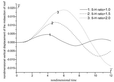
a) Vertical displacement of the midsection of roof
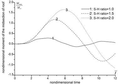
b) Moment of the midsection of roof
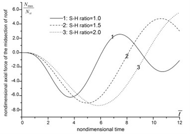
c) Axial force of the midsection of roof
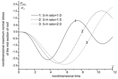
d) Maximum normal stress of the midsection of roof
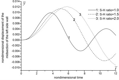
e) Horizontal displacement of the midsection of the left side wall
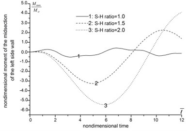
f) Moment of the midsection of the left side wall
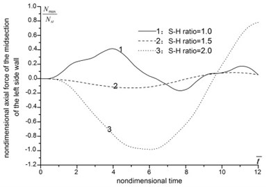
g) Axial force of the midsection of the left side wall
h) Vertical displacement of the midsection of floor
The results are demonstrated in Fig. 5. As general trend, the displacement, moment, axial force and normal stress of structure increase along with the decrease of foundation-structure wave impedance ratio, and the peak values delay. However, when the foundation is soft enough, this trend reverses in some case. The axial force of the midsection of roof, and the moment of the midsection of side walls are decrease when foundation-structure wave impedance ratio decreases from 0.26 to 0.17. And the moment of the midsection of roof and the axial force of the midsection of side wall increase by several times when foundation-structure wave impedance ratio decreases from 0.97 to 0.17.
The analysis indicates that a good foundation tends to weaken the dynamic effects of seismic waves, restrains structure deformation and reduces the internal forces. When the foundation condition transforms from rock to soil, in other words, when the foundation-structure wave impedance ratio decrease to a relative small value, the internal forces of structure are going to increase apparently, and will weaken the dynamic stability of underground structures.
Fig. 5The influence of foundation condition
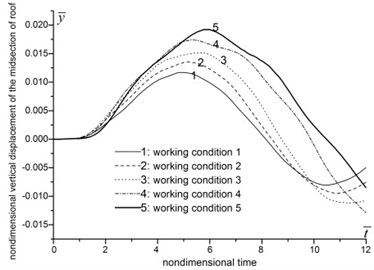
a) Vertical displacement of the midsection of roof
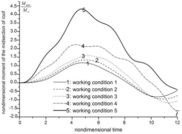
b) Moment of the midsection of roof
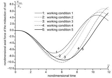
c) Axial force of the midsection of roof
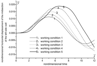
d) Horizontal displacement of the midsection of the left side wall
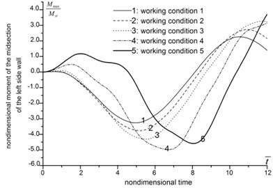
e) Moment of the midsection of the left side wall
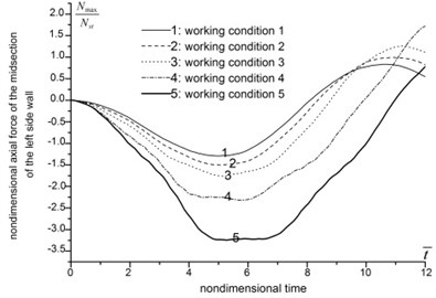
f) Axial force of the midsection of the left side wall
4.3.3. The validation of the results
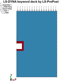
In order to validate the results of the presented method, we conduct the computation example by LS-DYNA. The numerical model is shown as Fig. 6. The nondimensional vertical displacement of the midsection of roof is computation for validation. The comparison results are demonstrated in Fig. 7.
Fig. 6The computation model of LS-DYNA
Form Fig. 7 we can see mainly three differences:
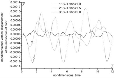
Firstly, the peak displacements computed by the presented method are bigger than the LS-DYNA method, by 10.58 %, 11.97 % and 6.14 % under conditions of 1.0, 1.5 and 2.0, respectively.
Secondly, the times correspond to the peak displacement under different conditions are not agreed well. When 1.0, the peak displacement of the presented method apear earlier than the LS-DYNA method. When 2.0, the contrary is the case. When 1.5, the time corresponds to the peak displacement agrees, with a relative error of lower than 1 %.
Thirdly, the results of the presented method has a vibration mode: the deformations rebound after the peak and reverse deformations appear with damped amplitudes. However, the results of LS-DYNA method attenuation to zero in one cycle.
Fig. 7The comparison of results between the presented method and LS-DYNA
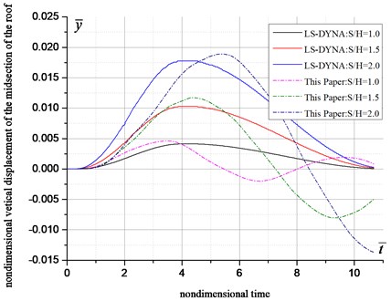
The latter two differences are results from the different processing method of damping. And the first deviation is results from the method itself. More validation works about internal forces indicate that the presented method gives a safer design with an acceptable deviation.
5. Conclusions
Through analysis, conclusions can be drawn as follows:
1) A semi-analytical analysis procedure is established based on matrix force method. The main equations are deduced and solving method is proposed. The advantage of presented method lies in the high efficiency in the determination of the movement parameters and structural internal forces.
2) A case study is implemented to investigate the influence of span-height ratio and foundation-structure wave impedance ratio. The dynamic response of box-type structure can be significantly influenced by the span-height ratio as well as the foundation conditions.
3) Results are presented nondimensionally to obtain clear physical understanding of the dynamic response of structure. The results are independent of dimension and can extend to structures with different size and working conditions.
References
-
Ma Wei Investigations on effects of blast vibration and behaviors of impacting failure of underground pipeline structures. Journal of PLA University of Science and Technology (Natural Science Edition), Vol. 9, Issue 1, 2008, p. 39-46.
-
Gran J. K., Senserny P. E., Groethe M. A., Chitty D., Trulio J. Dynamic response of an opening in jointed rock. International Journal of Rock Mechanics and Mining Science, Vol. 35, Issue 8, 1998, p. 1021-1035.
-
Esmaeili M., Vahdani S., Noorzad A. Dynamic response of lined circular tunnel to plane harmonic waves. Tunnelling and Underground Space Technology, Vol. 21, Issue 5, 2006, p. 511-519.
-
Feldgun V. R., Kochetkov A. V., Karinski Y. S., Yankelevsky D. Z. Blast response of a lined cavity in a porous saturated soil. International Journal of Impact Engineering, Vol. 35, Issue 9, 2008, p. 953-966.
-
Ma Guo-wei, Zhou Hong-yuan, Lu Yong, Chong Karen In-structure shock of underground structures: a theoretical approach. Engineering Structures, Vol. 32, Issue 12, 2010, p. 3836-3844.
-
Chen Yue-hua, Jin Guo-yong, Zhu Ming-gang, Liu Zhi-gang, Du Jing-tao, Li Wen Vibration behaviors of a box-type structure built up by plates and energy transmission through the structure. Journal of Sound and Vibration, Vol. 331, Issue 4, 2012, p. 849-867.
-
Morris J. P., Rubin M. B., Blair S. C., Glenn L. A., Heuze F. E. Simulations of underground structures subjected to dynamic loading using the distinct element method. Engineering Computations, Vol. 21, Issue 2, 2004, p. 384-408.
-
Wu Cheng-qing, Hao Hong Numerical simulation of structural response and damage to simultaneous ground shock and air blast loads. International Journal of Impact Engineering, Vol. 34, Issue 3, 2007, p. 556-572.
-
Olarewaju A. J., Kameswara Rao N. S. V., Mannan M. A. Response of underground pipes due to blast loads by simulation – an overview. Electronic Journal of Geotechnical Engineering, Vol. 15, 2010, p. 831-852.
-
Fan Peng-xian, Wang Ming-yang, Feng Shu-fang, Li Jie, Wang De-rong Analysis of dynamic response of deep-buried circular tunnel to explosion seismic wave. Chinese Journal of Rock Mechanics and Engineering, Vol. 32, Issue 4, 2013, p. 671-680.
-
Fan Peng-xian, Wang Ming-yang, Feng Shu-fang, Wang De-rong, Li Jie The dynamic response of underground straight-wall-round-arch structure to the explosion seismic wave. Journal of Vibration and Shock, Vol. 33, Issue 22, 2014, p. 183-187.
-
Yong Lu, Zhonghi Wang, Karen Chong A comparative study of buried structure in soil subjected to blast load using 2D and 3D numerical simulations. Soil Dynamic and Earthquake Engineering, Vol. 25, Issue 4, 2005, p. 275-288.
-
Clough R., Penzien J. Dynamics of Structures. Computers and Structures, Berkeley, 1995.
-
Gerogiadis H. G., Vamvatsikos D., Vardoulakis I. Numerical implementation of integral-transform solution to Lamb’s point-load problem. Computational Mechanics, Vol. 24, Issue 1, 1999, p. 90-99.
About this article
The authors gratefully acknowledge the financial support from Chinese Postdoctoral Science Foundation (Grant Nos. 2013M542427 and 2015T81074).
