Abstract
In this investigation, a Spectro-Geometric Method (SGM) is presented for the in-plane vibration analysis of sector plates with an arbitrary inclusion angle, and general boundary conditions along each of its edges. Unlike in most existing studies where solutions are often developed for a particular type of boundary conditions, the current method can be generally applied to a wide range of boundary conditions with no need of modifying solution algorithms and procedures; that is, the in-plane displacement functions are invariably expressed as an accelerated trigonometric series expansion and different boundary conditions can be easily dealt with through modifying the stiffness values for restraining springs in the same way as varying other model parameters such as Young’s modulus and mass density. The expansion coefficients are considered as the generalized coordinates, and determined using the Rayleigh-Ritz technique. The effectiveness and reliability of the current method are demonstrated by the calculated modal properties for sector plates with a range of different combinations of boundary conditions and inclusion angles up to 2π.
1. Introduction
Sector plates are widely used in industrial applications as a stand-alone structure or a constituent structural component. The dynamic characteristics of sector plates are thus of great interest to engineers and designers. Although there is a vast pool of studies about the out-of-plane vibrations of sector plates, few in-plane vibration results are available for sector plates [1]. The reason may be that the modes related to in-plane vibrations typically fall outside the dominant frequency bands of excitations. In some practical engineering applications, however, the in-plane vibrations need to be taken into consideration. Furthermore, some studies have shown that the in-plane vibrations can play a prominent role in affecting the sound radiation and transmissions of vibration energies in build-up structures [2, 3].
Onoe [4] first obtained the in-plane displacements and frequency equations of circular disks based on Love’s theory. In his study, he utilized trigonometric functions in the circumferential direction and Bessel functions in the radial direction. An error in the eigen-functions for compound modes was identified in his latter works [5]. Holland [6] used trigonometric and Bessel functions to study the in-plane vibration of a free circular plate. The frequency parameters for different Poisson’s ratios were presented and compared with the results previously given by Onoe [4, 5]. Chen, et al. [7] studied extensional (in-plane) vibration of thin plates of Hookean material with different shapes. Based on plane stress condition, a general solution of the governing differential equation was derived for an arbitrarily shaped plate with the boundary conditions being satisfied only in a least-square sense. Irie et al. [8] used a transfer matrix method to study the in-plane vibration of circular and annular plates with free and clamped boundary conditions specified at the inner and outer edges, respectively. The frequency parameters were presented for circumferential wave numbers from 0 to 4. The circular plates were treated as a limiting case of an annular plate when the radius of the inner edge tends to zero. Farag and Pan [9] examined the in-plane vibration of circular plates clamped at the outer edges. The mode functions were expressed in terms of trigonometric functions in the circumferential direction and the series expansion of Bessel functions in the radial direction. The frequency parameters were compared with finite element results and the data published previously. Recently, Park [10] derived exact frequency equations for in-plane vibration of a clamped circular plate using Hamilton’s principle. His results were validated by finite element results and those from Farag and Pan [9]. Bashmal et al. [11] derived a generalized formula for in-plane vibration of circular annular plates under various combinations of classical boundary conditions. Bashmal, et al. [12] also studied the in-plane vibration behavior of an annular disk with elastic constraints at the inner and outer boundaries. Ravari, et al. [13] derived the frequency equation for the in-plane vibration of orthotropic circular annular plates. Kim et al. [14] studied the in-plane vibration of a circular plate with its outer edge being restrained elastically. The mode shapes are expressed in terms of trigonometric functions in the circumferential direction and modal functions in the radial direction. The elastic boundary conditions at outer edge were represented by circumferentially distributed radial and tangential stiffness. Shi et al. [15] investigated the in-plane vibration characteristics of annular sector plates with elastic boundary conditions.
It should be pointed out that all the above studies are focused on annular and circular plate problems to which the solutions can be reduced to solving two coupled ordinary differential equations with respect to the radial dimension. Using variational approach, Seok and Tiersten [16] investigated the in-plane vibration of a cantilevered annular sector plate where the plate is fixed on one radial edge, and free on the rest. Singh, et al. [17] studied free in-plane vibration of non-rectangular plate, including annular sector plates.
When an analytical solution is sought for a sector plate, its inclusion (or sector) angle is typically limited within a range; a sector plate with re-entrant sector angle (larger than π) is rarely attempted in the literature. It is also widely accepted that an analytical solution is only possible for a sector plate which is simply supported along, at least, two radial edges. To the best authors’ knowledge, there is no reported study about the in-plane vibration of a sector plate with elastically restrained edges. However, sector plates with general elastic boundary conditions have always been of research and application interests to many engineers [18-20]. Recently, Shi et al. [21] presented a so-called Spectro-Geometric Method (SGM) for the free in-plane vibration analysis of orthotropic rectangular plates with arbitrary elastic supports. In this investigation, the spectro-geometric method (SGM) is extended to the in-plane vibration analysis of sector plates with arbitrary inclusion angles and boundary conditions. Numerical results are presented to verify the accuracy and reliability of the current solution method.
2. Theoretical formulation
2.1. Description for the plates
Fig. 1 shows an annular sector plate with uniform thickness h, inner radius a, outer radius b, width R in radial direction, and sector angle ϕ. The geometry and dimensions are defined in an orthogonal cylindrical coordinate system (r, θ, z). A local coordinate system (s, θ, z) is also shown in the Fig. 1 which will be used in the analysis. In this investigation, we deal with the in-plane vibrations of sector plates with arbitrary boundary conditions in a unified manner. The material of the plate is assumed to be isotropic, having a mass density ρ, Young’s modulus E and Poisson’s ratio μ. The displacement fields at a material point are denoted as u and v in the radial and circumferential directions, respectively. Circular sector plates can be viewed as the special cases of an annular sector plate when its radius ratio a/b is a very small number. The annular sector plate can be accordingly defined as:
The boundary conditions are generally specified in terms of elastic restraints with independent stiffness values. All the classical homogeneous boundary conditions can be considered as the special cases when the stiffness values become extremely large or small. For instance, a free edge condition is simply created by setting to zero the stiffness values for the two sets of springs.
Fig. 1Sketch of an elastically restrained annular sector plate
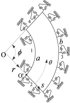
a) An annular sector plate
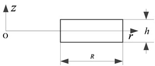
b) Cross-section
2.2. Series representations of the displacement functions
Regardless of boundary conditions and sector angles, the displacement functions will be invariably sought as trigonometric series expansions in the form of:
+∑∞m=0∑2n=1Cmncosλrmssinλθnθ,
and:
+∑∞m=0∑2n=1Fmncosλrmssinλθnθ,
where λrm=mπ/R, λθn=nπ/ϕ; Amn, Bmn, Cmn, Dmn, Emn, Fmn denote the coefficients of series expansions.
It should be pointed out that in the above series expansions the cosine terms (Fourier series) alone will constitute a complete set which is adequate to span a vector space of infinite dimensions. But this form of series representation of a sufficiently smooth function on a compact interval is usually slow converged due to the possible discontinuities at the endpoints of the interval after its periodic extension as implied by the Fourier representation. By including these auxiliary terms, the in-place displacements are governed by second-order differential equations over the plate, their first derivatives are mathematically required to be continuous and second derivatives exist everywhere. Thus, these series are able to expand and uniformly converge to any function f(s,θ)∈C1 for ∀(s,θ)∈D: ([0, R]×[0, ϕ]). According to the convergence theorem [22], the convergence (rate) for the series expansion of a periodic function is proportional to the degree of smoothness of the function. Therefore, the series expressions in Eqs. (2)-(3) are guaranteed to converge at a substantially improved rate for any boundary conditions. The accompanying benefits were previously demonstrated for beams and plates with general boundary conditions [21, 23]. As a matter of fact, this subtraction techniques have been proposed by mathematicians as a means to accelerate the convergence of the Fourier series expansion for an explicitly given function [24].
The expansion coefficients for the sine terms are determined only by the first derivatives at the boundaries of the solution domain. Strictly speaking, the sine terms are “redundant” in view of the fact that the basis set (that is, the infinite cosine terms) is complete. More explicitly, the coefficients for the sine terms can be shown to be dependent on those for the cosine series under the condition that the (cosine) series converges fast enough so that it can be differentiated term-by-term. In such a case, for example, the relationships between the coefficients for sine and cosine terms can be established through the boundary conditions. A strong form of solution can be subsequently obtained by letting the series satisfy the governing differential equations on a point-wise basis (i.e., at each field point). Such a solution may be considered exact in the sense that the solution error can be controlled within any pre-specified tolerance.
In seeking an approximate solution, the truncated version of the series expansions will have to be adopted. As a result, all the expansion coefficients, including those for the sine terms, will be treated equally as the generalized coordinates and solved from, such as, the Rayleigh-Ritz procedure. It shall be noted that since the trial solution is constructed with the same degree of smoothness as required for a strong solution, the approximate and exact solutions are equivalent mathematically (this is evident from integrating, by part, the appropriate energy equation). In terms of numerical implementations, however, the approximate solution is far more advantageous, especially when the modeling method is extended to structures involving many plates or other structural elements.
2.3. Solution for the sector plate
For small deformations, the strain-displacement relations in local cylindrical coordinate system (s, θ, z) can be expressed as:
The strain energy of the sector plate is given as:
In terms of displacements, stresses can be calculated from:
Submitting Eqs. (4)-(6) and (8) into Eq. (7) will lead to the following expression for the strain energy:
+2u(s+a)2∂v∂θ+1(s+a)2(∂v∂θ)2
+1-μ(s,θ)2(1s+a∂u∂θ+∂v∂s-vs+a)2}(s+a)dsdθ,
where G(s,θ)=E(s,θ)h(s,θ)/(1-μ2(s,θ)) is the extentional rigidity of the plate.
By neglecting rotary inertia, the kinetic energy of an annular sector plate can be written as:
where ω is the frequency in radians.
When an edge of the plate is elastically restrained, two sets of springs of arbitrary stiffness distributions will be specified accordingly, which directly describe the relationships between the forces and displacements along the edge. All the familiar homogeneous boundary conditions (i.e., simply supported, free and fixed) can be readily realized by setting the constants of restraint springs to either zero or an extremely large number. The stiffness for any of the restraining spring is allowed to vary continuously or disruptively.
In seeking a weak form of solution, the presence of the restraining springs can be easily accounted for in terms of potential energies stored in the boundary springs:
+12∫ϕ0[kns0(θ)u2+kps0(θ)v2](s+a)dθ
+12∫R0[kpθ0(θ)u2+knθ0(θ)v2](s+a)dθ,
where kps0, kps1 (kpθ0, kpθ1) are the stiffnesses for tangential springs, respectively, at s= 0 and R (θ= 0 and ϕ); kns0, kns1 (knθ0, knθ1) represente the stiffnesses for normal springs, respectively, at s= 0 and R (θ= 0 and ϕ).
The Lagrangian function for an annular sector plate can be finally expressed as:
In the above derivations, the thickness of the plate, material properties (Young’s modulus, Poisson’s ratio, and mass density) and the stiffness for each elastic restraint are all generally specified as an arbitrary function of the spatial coordinates. To unify the descriptions and facilitate the analytical calculations of the involved integrals, all these distribution functions can be expanded into 1-D or 2-D Fourier cosine series.
By substituting the displacement expressions, Eqs. (2) and (3) into the Lagrangian, Eq. (12), and minimizing the result with respect to the series coefficients, one is able to yield a final system of equation as:
where E is a vector that contains the unknown series expansion coefficients, and K and M are the stiffness and mass matrices, respectively. For conciseness, the detailed expression for stiffness and mass matrices will not be shown here.
The natural frequencies and eigenvectors of sector plates can now be easily and directly determined from solving a standard matrix eigenvalue problem. Each of the eigenvectors actually contains the series coefficients for the corresponding mode; the mode shape can be simply obtained by using Eqs. (2) and (3). Although this investigation is focused on the free vibration of annular sector plates, the dynamic response of the plates to any applied load can be easily considered by including the work done by this load in the Lagrangian, which will eventually lead to a force term on the right side of Eq. (13).
It should also be noted that the current method is particularly advantageous in obtaining other variables of interest such as power flows. Since the displacements are constructed sufficiently smooth as required in a strong formulation, post-processing the solution can be done easily through appropriate mathematical operations, including term-by-term differentiations.
3. Results and discussions
Several numerical examples will be presented in this section to demonstrate the accuracy, reliability and versatility of the presented method. Throughout these examples, the mass density, Young’s modulus and Poisson’s ratio are specified as: ρ= 7800 kg/m3, E= 2.0×10¹¹ Pa and μ= 0.3. In identifying the boundary conditions, letters C and F have been used to indicate the clamped and free boundary condition along an edge, respectively. Thus, the boundary conditions for a plate are fully specified by using four letters with the first one indicating the B.C. along the first edge, r=a. The remaining (the second to the fourth) edges are ordered in the counterclockwise direction.
We first consider an annular sector plate which is fully clamped along each edge (C-C-C-C) to validate the current results. The geometry parameters of plate are as follows: cutout ratio a/b= 0.5 and sector angle ϕ=π/3. A clamped edge refers to a special case of the elastic supports when the stiffnesses for both of the (normal and tangential) restraining springs become infinity (represented by a very large number, 1013, in the actual calculations). The first six non-dimensional frequency parameters, Ω=ωb√ρ(1-μ2)/E, are presented in Table 1 for different series truncation numbers: M=N= 4, 5,…, 12. Two sets of reference results taken from Ref. [17] and obtained using an FEM (ABAQUS) model are also given there. A good convergence behavior is observed. Of equal importance, the solution also shows an excellent numerical stability, meaning that the values essentially remain the same as the truncation numbers become increasingly large. Once the convergence behavior is understood, the series will be consistently truncated to M=N= 10 in all the subsequent calculation.
In the very limited existing studies, the sector angles are typically assumed to be less than π. Although it is not clear whether ϕ=π inherently constitutes a pivoting point for mathematically solving sector plate problems, it has been a limit point practically defining the previous investigation. However, the value of the sector angle appears to have no binding effect on the current solution procedures as described earlier. In Table 2, the first six frequency parameters, Ω=ωb√ρ(1-μ2)/E, are shown for the completely clamped (C-C-C-C) annular sector plates (a/b= 0.5) with various sector angles. The results match very well with those from Ref. [17] and an FEM model.
Table 1Frequency parameters Ω=ωbρ(1-μ2)/E for a C-C-C-C annular sector plate (a/b= 0.5 and ϕ=π/3)
Mode sequence | ||||||
1 | 2 | 3 | 4 | 5 | 6 | |
M=N= 4 | 5.3397 | 6.5689 | 7.1412 | 8.2149 | 8.6793 | 8.8482 |
M=N= 5 | 5.3384 | 6.5682 | 7.1402 | 8.2130 | 8.6776 | 8.8457 |
M=N= 6 | 5.3382 | 6.5681 | 7.1401 | 8.2115 | 8.6744 | 8.8442 |
M=N= 7 | 5.3379 | 6.5679 | 7.1399 | 8.2111 | 8.6741 | 8.8437 |
M=N= 8 | 5.3378 | 6.5678 | 7.1398 | 8.2108 | 8.6736 | 8.8433 |
M=N= 9 | 5.3377 | 6.5678 | 7.1398 | 8.2106 | 8.6735 | 8.8432 |
M=N= 10 | 5.3377 | 6.5678 | 7.1398 | 8.2104 | 8.6734 | 8.8430 |
M=N= 11 | 5.3377 | 6.5678 | 7.1398 | 8.2104 | 8.6734 | 8.8430 |
M=N= 12 | 5.3377 | 6.5678 | 7.1398 | 8.2104 | 8.6734 | 8.8430 |
Ref. [17] | 5.3385 | 6.6046 | 7.0882 | 8.2349 | 8.6217 | 8.8282 |
FEM | 5.3391 | 6.5690 | 7.1431 | 8.2127 | 8.6778 | 8.8469 |
Table 2Frequency parameters Ω=ωbρ(1-μ2)/E for a C-C-C-C annular sector plate (a/b= 0.5)
ϕ | Method | Mode sequence | |||||
1 | 2 | 3 | 4 | 5 | 6 | ||
π/2 | Present | 4.5320 | 6.0304 | 6.5406 | 6.5746 | 7.2092 | 7.7243 |
Ref. [17] | 4.5385 | 6.0535 | 6.0535 | 6.6578 | 7.2260 | 7.7108 | |
FEM | 4.5327 | 6.0314 | 6.5425 | 6.5758 | 7.2115 | 7.7276 | |
π | Present | 3.9798 | 4.5089 | 5.2279 | 5.9389 | 6.3407 | 6.3519 |
FEM | 3.9805 | 4.5091 | 5.2276 | 5.9384 | 6.3414 | 6.3524 | |
3π/2 | Present | 3.8707 | 4.1223 | 4.5018 | 4.9647 | 5.4595 | 5.9162 |
FEM | 3.8710 | 4.1223 | 4.5013 | 4.9635 | 5.4578 | 5.9132 | |
16π/9 | Present | 3.8453 | 4.0274 | 4.3093 | 4.6657 | 5.0682 | 5.4855 |
FEM | 3.8469 | 4.0286 | 4.3099 | 4.6655 | 5.0671 | 5.4822 | |
2π | Present | 3.8320 | 3.9769 | 4.2045 | 4.4977 | 4.8374 | 5.2025 |
FEM | 3.8337 | 3.9786 | 4.2061 | 4.4992 | 4.8387 | 5.2040 | |
For any given modal frequency, the corresponding mode shape can be readily determined from Eqs. (2) and (3). As an example, the first six mode shapes are plotted in Fig. 2 for the C-C-C-C annular sector plate with ϕ=π. It is seen that although those are the lower-order modes, they tend to exhibit unfamiliar and more complicated patterns than their counterparts in the flexural vibrations. For instance, the extension-compression deformation in one mode (or region) can quickly turn into a shear state in another mode (or region). This characteristic, however, may have some useful implications to the non-destructive evaluation of material and structural parameters or monitoring of structural conditions or failures, as evidenced by the more distinctively different modal signatures and more probing natures of the in-plane displacement fields. The complexity of mode shapes also graphically confirms the fact that the displacement fields can no longer be determined by the separation of variables for a plate under general boundary condition.
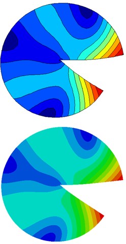
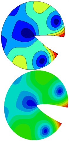
In this investigation, we deal with the in-plane vibrations of thin sector plates with arbitrary boundary conditions in a unified manner. As the inner radius of the sector plate tends to zero, the annular sector plate coincides with the circular sector plate. In the previous paper [25], this configuration is practically realized by letting a/b= 1×10⁻⁵. Table 3 lists the frequency parameters for fully free sector plates with various cutout ratios and sector angles. This problem is about a completely free sector plate, which represents a classical, but quite challenging, case for validating the solution. Under the current framework, the free edge condition is easily realized by setting all the stiffness constants to zero. Since the in-plane vibration problems of circular sector plate are rarely investigated, the FEM results are used as the reference. A good agreement is observed between the current and the FEM solutions. The results have demonstrated that the radius ratio 10-5 is considered adequately small to practically allow a decent prediction of the dynamic behaviors of the corresponding circular sector plate. A visual comparison of mode shape is shown in Fig. 3. The results convincingly demonstrate that the present series solution is accurate and reliable.
Fig. 2The mode shapes for a C-C-C-C annular sector plate with sector angle ϕ=π and cutout ratio a/b= 0.5. (The dashed background grid is the original undeformed configuration)
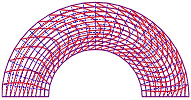
a) First mode
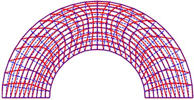
b) Second mode
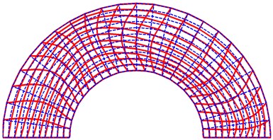
c) Third mode
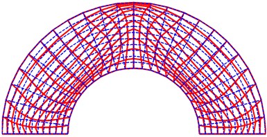
d) Fourth mode
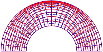
e) Fifth mode
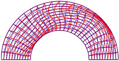
f) Sixth mode
Table 3Comparison of frequency parameters Ω=ωbρ(1-μ2)/E for fully free circular and annular sector plates
ϕ | a/b | Method | Mode sequence | |||||
1 | 2 | 3 | 4 | 5 | 6 | |||
π/6 | 10-5 | Present | 1.5604 | 2.9922 | 3.5813 | 4.4336 | 5.4987 | 5.6205 |
FEM | 1.5601 | 2.9922 | 3.5814 | 4.4336 | 5.4987 | 5.6221 | ||
0.3 | Present | 2.7882 | 4.3432 | 4.7680 | 5.6629 | 6.2355 | 6.7435 | |
FEM | 2.7882 | 4.3434 | 4.7687 | 5.6642 | 6.2368 | 6.7444 | ||
π | 10-5 | Present | 1.1360 | 1.7546 | 1.8266 | 2.3500 | 2.5294 | 2.8974 |
FEM | 1.1361 | 1.7546 | 1.8268 | 2.3503 | 2.5297 | 2.8978 | ||
0.3 | Present | 0.6947 | 1.5162 | 1.7022 | 2.4227 | 2.4317 | 2.9291 | |
FEM | 0.6947 | 1.5160 | 1.7023 | 2.4227 | 2.4316 | 2.9290 | ||
16π/9 | 10-5 | Present | 0.4581 | 1.0323 | 1.3985 | 1.6350 | 1.8257 | 1.9226 |
0.3 | Present | 0.2232 | 0.5060 | 0.9641 | 1.4736 | 1.5885 | 1.8013 | |
Fig. 3The mode shapes for a fully free circular sector plate with sector angle ϕ= 16π/9. (The first row is calculated by the current approach, the second row is obtained using FEM)

a) First mode
b) Second mode
c) Third mode
In the literature, there are two distinct types of ‘simply supported’ boundary conditions for the in-plane vibration of a plate [26]. For convenience, these two types of simply supported conditions are designated by SS1 and SS2. An edge associated with the first type, SS1, is characterized by the fact that the plate displacement parallel to the edge is specified to zero as well as normal stress perpendicular to the edge. In the numerical calculation, it can be physically realized by setting the stiffness of the tangential and normal springs to ∞ and 0, respectively. The second type is an exactly opposite scenario.
Table 4Frequency parameters Ω=ωbρ(1-μ2)/E for C-SS1-C-SS1 sector plates
ϕ | a/b | Method | Mode sequence | |||||
1 | 2 | 3 | 4 | 5 | 6 | |||
π/6 | 10-5 | Present | 2.2668 | 4.1503 | 6.0185 | 6.2555 | 7.8291 | 7.8821 |
0.5 | Present | 3.7821 | 6.8633 | 7.4685 | 8.2440 | 10.359 | 11.174 | |
π | 10-5 | Present | 1.9570 | 2.2668 | 3.0473 | 3.1784 | 3.9630 | 4.0858 |
FEM | 1.9571 | 2.2671 | 3.0476 | 3.1790 | 3.9638 | 4.0870 | ||
0.5 | Present | 3.7821 | 3.9739 | 4.4861 | 5.1769 | 5.8617 | 6.2792 | |
FEM | 3.7838 | 3.9756 | 4.4879 | 5.1788 | 5.8641 | 6.2834 | ||
16π/9 | 10-5 | Present | 2.0238 | 2.2205 | 2.2668 | 2.7296 | 3.2526 | 3.2891 |
0.5 | Present | 3.7821 | 3.8441 | 4.0229 | 4.2994 | 4.6485 | 5.0415 | |
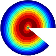
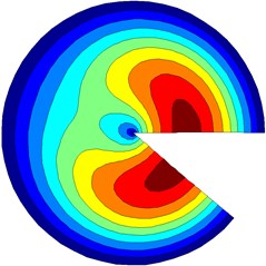
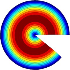
The first six non-dimensional frequency parameters, Ω=ωb√ρ(1-μ2)/E, are given in Table 4 for sector plates with clamped and simply supported conditions (SS1) along the circumferential and radial edges, respectively. To understand the difference between the SS1 and SS2 boundary conditions, the problems are re-solved by only replacing the SS1 conditions with SS2 while all the other parameters are kept the same. The results are shown in Table 5. A comparison of results in Tables 4 and 5 has revealed the noticeable difference between the SS1 and SS2 boundary conditions, as manifested in values of the frequency parameters. However, some frequency parameters appear to be unaffected even though the modal sequence is clearly changed. It is interesting to see that the first frequency parameters in Table 4 for annular sector plates (a/b= 0.5) are not affected by the sector angles. The first three mode shapes for C-SS1-C-SS1 sector plates (a/b= 10-5 and ϕ= 16π/9) are plotted in Fig. 4. The results clearly show that the boundary springs have played a dominant role in these modes. In other words, one has to change the spring stiffness to effectively modify the modal properties.
Table 5Frequency parameters Ω=ωbρ(1-μ2)/E for C-SS2-C-SS2 sector plates
ϕ | a/b | Method | Mode sequence | |||||
1 | 2 | 3 | 4 | 5 | 6 | |||
π/6 | 10-5 | Present | 3.8313 | 6.2556 | 7.0148 | 7.8287 | 9.1762 | 10.172 |
0.5 | Present | 6.3925 | 6.8633 | 8.2435 | 10.359 | 11.192 | 11.880 | |
π | 10-5 | Present | 1.9570 | 3.0473 | 3.1784 | 3.8316 | 3.9630 | 4.0858 |
FEM | 1.9571 | 3.0476 | 3.1790 | 3.8320 | 3.9638 | 4.0870 | ||
0.5 | Present | 3.9739 | 4.4861 | 5.1769 | 5.8617 | 6.2792 | 6.3322 | |
FEM | 3.9743 | 4.4865 | 5.1774 | 5.8623 | 6.2800 | 6.3330 | ||
16π/9 | 10-5 | Present | 2.0238 | 2.2205 | 2.7296 | 3.2526 | 3.2891 | 3.3577 |
0.5 | Present | 4.0229 | 4.2994 | 4.6485 | 5.0417 | 5.4466 | 5.8241 | |
Fig. 4The mode shapes for a C-SS1-C-SS1 sector plate (a/b= 10-5 and ϕ= 16π/9)
a) First mode
b) Second mode
c) Third mode
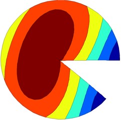
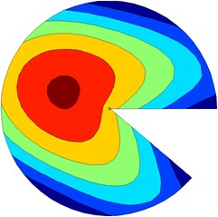
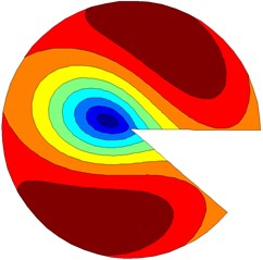
All the examples considered thus far have been limited to the classical boundary conditions which have been treated as the special cases of elastically restrained edges. Our attention will now be direct to elastically restrained plates. We first consider a simply supported (SS2-SS2-SS2) circular sector plate (a/b= 10-5, ϕ= 3π/2) with a uniform tangential restraint along each edge. This condition can be realized by setting kps1=kpθ0=kpθ1=K and infinite stiffness for all other restraining springs. The first six frequency parameters, Ω=ωb√ρ(1-μ2)/E, are presented in Table 6 for several different spring stiffness values. For a very large stiffness value, this edge condition will effectively degenerate to the familiar clamped condition. The second example concerns a sector plate (ϕ=16π/9) elastically supported along all edges. The stiffness values for the normal and tangential restraints are both set equal to 108 N/m2. The first six frequency parameters are shown in Table 7 for sector plates with different radius ratios. Since the elastically restrained plates are rarely investigated, the FEM results are used as the reference. A good agreement is observed between the current and the FEM solutions. It can be seen that the increase of the radius ratio leads to increase of the frequency parameter of the plate. Fig. 5 shows the first three mode shapes for sector plates (a/b= 10-5 and ϕ=16π/9) with identical restraints at all edges K=108 N/m2.
In addition to its wide applicability to a range of boundary conditions, the current solution method is generally good for any inclusion angle. Although the results were not shown here, we have actually validated the model for an annular “sector” plate with a 2π inclusion angle. While making no attempt to determine how small a sector angle is allowed in this model, we can reasonably assume that the threshold will set up by the fact that the corresponding annular sector will have to behave like a plate, rather than a bar (of varying cross-section) as the sector angle becomes sufficiently small. Being applicable to any inclusion angle is one of the important advantages of the current solution method in view that the actual limitations of other solution techniques were often not stated clearly in the (limited) existing publications.
Table 6Frequency parameters Ω=ωbρ(1-μ2)/E for SS2-SS2-SS2 sector plates (ϕ= 3π/2) with uniform elastic restraint kps1=kpθ0=kpθ1=K
K (N/m2) | Method | Mode sequence | |||||
1 | 2 | 3 | 4 | 5 | 6 | ||
1 | Present | 0.8793 | 1.7319 | 2.4129 | 2.4818 | 2.5076 | 3.0475 |
FEM | 0.8776 | 1.7320 | 2.4132 | 2.4819 | 2.5077 | 3.0476 | |
104 | Present | 0.8794 | 1.7320 | 2.4130 | 2.4818 | 2.5074 | 3.0475 |
FEM | 0.8783 | 1.7321 | 2.4136 | 2.4821 | 2.5076 | 3.0477 | |
108 | Present | 1.5094 | 2.1765 | 2.5713 | 2.6622 | 2.8940 | 3.1289 |
FEM | 1.5063 | 2.1732 | 2.5706 | 2.6617 | 2.8932 | 3.1269 | |
∞ | Present | 2.3609 | 2.7548 | 3.2007 | 3.6334 | 3.7276 | 3.7623 |
FEM | 2.3605 | 2.7550 | 3.2003 | 3.6340 | 3.7278 | 3.7628 | |
Table 7Frequency parameters Ω=ωbρ(1-μ2)/E for sector plates (ϕ= 16π/9) with identical restraints at all edges K= 108 N/m2
a/b | Method | Mode sequence | |||||
1 | 2 | 3 | 4 | 5 | 6 | ||
10-5 | Present | 0.9592 | 0.9984 | 1.2594 | 1.4121 | 1.6924 | 1.9470 |
FEM | 0.9611 | 0.9997 | 1.2577 | 1.4073 | 1.6878 | 1.9443 | |
0.3 | Present | 1.1168 | 1.1357 | 1.2752 | 1.3300 | 1.5126 | 1.7824 |
FEM | 1.1160 | 1.1351 | 1.2749 | 1.3297 | 1.5121 | 1.7820 | |
0.5 | Present | 1.3206 | 1.3256 | 1.4053 | 1.4441 | 1.5432 | 1.6975 |
0.7 | Present | 1.7128 | 1.7129 | 1.7446 | 1.7790 | 1.8204 | 1.8716 |
Fig. 5The mode shapes for a sector plate (a/b= 10-5 and ϕ= 16π/9) with identical restraints at all edges K= 108N/m2
a) First mode
b) Second mode
c) Third mode
4. Conclusions
A general series solution has been developed for the in-plane vibration analysis of sector plates with arbitrary boundary conditions and inclusion angles. The in-plane displacement fields are invariably expressed as a new form of trigonometric series expansions with drastically improved convergence as compared with the conventional Fourier series. Unlike most of the existing methods in which each of the frequency parameters is calculated, repeatedly and iteratively, from a nonlinear characteristic equation, all the modal parameters can now be easily and simultaneously determined from solving a standard matrix eigenvalue problem. The proposed method provides a unified means for extracting the modal parameters and predicting the in-plane vibrations of sector plates with different boundary conditions. Of equal importance, the current solution is generally applicable to sector plates with any inclusion angle up to a full 360 degree. The excellent accuracy and convergence of the present solutions have been validated through a number of examples.
References
-
Leissa A. W. Vibration of Plates. U. S. Government Printing Office, Washington DC, 1969.
-
Bercin A. N. An assessment of the effects of in-plane vibrations on the energy flow between coupled plates. Journal of Sound and Vibration, Vol. 191, Issue 5, 1996, p. 661-680.
-
Lyon R. H. In-plane contribution to structural noise transmission. Noise Control Engineering Journal, Vol. 26, Issue 1, 1985, p. 22-27.
-
Onoe M. Contour vibrations of isotropic circular plates. The Journal of the Acoustical Society of America, Vol. 28, Issue 6, 1956, p. 1158-1162.
-
Onoe M. Gravest contour vibration of thin anisotropic circular plates. The Journal of the Acoustical Society of America, Vol. 30, Issue 7, 1958, p. 698.
-
Holland R. Numerical studies of elastic-disk contour modes lacking axial symmetry. The Journal of the Acoustical Society of America, Vol. 40, Issue 5, 1966, p. 1051-1057.
-
Chen S. S. H., Liu T. M. Extensional vibration of thin plates of various shapes. The Journal of the Acoustical Society of America, Vol. 58, Issue 4, 1975, p. 828-831.
-
Irie T., Yamada G., Muramoto R. Natural frequencies of in-plane vibration of annular plates. Journal of Sound and Vibration, Vol. 97, Issue 1, 1984, p. 171-175.
-
Farag N. H., Pan J. Modal characteristics of in-plane vibration of circular plates clamped at the outer edge. The Journal of the Acoustical Society of America, Vol. 113, Issue 4, 2003, p. 1935-1946.
-
Park C. Il. Frequency equation for the in-plane vibration of a clamped circular plate. Journal of Sound and Vibration, Vol. 313, Issue 1-2, 2008, p. 325-333.
-
Bashmal S., Bhat R., Rakheja S. In-plane free vibration of circular annular disks. Journal of Sound and Vibration, Vol. 322, Issue 1-2, 2009, p. 216-226.
-
Bashmal S., Bhat R., Rakheja S. In-plane free vibration analysis of an annular disk with point elastic support. Shock and Vibration, Vol. 18, Issue 4, 2011, p. 627-640.
-
Karamooz Ravari M. R., Forouzan M. R. Frequency equations for the in-plane vibration of orthotropic circular annular plate. Archive of Applied Mechanics, Vol. 81, Issue 9, 2011, p. 1307-1322.
-
Kim C. B., Cho H. S., Beom H. G. Exact solutions of in-plane natural vibration of a circular plate with outer edge restrained elastically. Journal of Sound and Vibration, Vol. 331, Issue 9, 2013, p. 2173-2189.
-
Shi X. J., Li W., Shi D. Y. Free in-plane vibrations of annular sector plates with elastic boundary supports. Proceedings of Meetings on Acoustics, Vol. 18, Issue 1, 2012, p. 1-11.
-
Seok J. W., Tiersten H. F. Free vibrations of annular sector cantilever plates. Part 2: in-plane motion. Journal of Sound and Vibration, Vol. 271, Issue 3-5, 2004, p. 773-787.
-
Singh A. V., Muhammad T. Free in-plane vibration of isotropic non-rectangular plates. Journal of Sound and Vibration, Vol. 273, Issue 1-2, 2004, p. 219-231.
-
Jomehzadeh E., Saidi A. R. Analytical solution for free vibration of transversely isotropic sector plates using a boundary layer function. Thin-Walled Structures, Vol. 47, Issue 1, 2009, p. 82-88.
-
Leissa A. W., Mcgee O. G., Huang C. S. Vibrations of sectorial plates having corner stress singularities. Journal of Applied Mechanics – Transactions of the ASME, Vol. 60, Issue 1, 1993, p. 134-140.
-
Ramaiah G. K., Vijayaku K. Natural frequencies of circumferentially truncated sector plates with simply supported straight edges. Journal of Sound and Vibration, Vol. 34, Issue 1, 1974, p. 53-61.
-
Shi D. Y., Wang Q. S., Shi X. J., Pang F. Z. A series solution for the in-plane vibration analysis of orthotropic rectangular plates with non-uniform elastic boundary constraints and internal line supports. Archive of Applied Mechanics, Vol. 85, Issue 1, 2015, p. 51-73.
-
Tolstov G. P. Fourier Series. Prentice Hall, Englewood Cliffs, NJ, 1965.
-
Li W. L. Vibration analysis of rectangular plates with general boundary conditions. Journal of Sound and Vibration, Vol. 273, Issue 3, 2004, p. 619-635.
-
Baszenski G., Delvos F. J., Tasche M. A united approach to accelerating trigonometric expansions. Computers and Mathematics with Applications, Vol. 30, Issue 3-6, 1995, p. 33-49.
-
Shi X. J., Shi D. Y., Li W. L., Wang Q. S. A unified method for free vibration analysis of circular, annular and sector plates with arbitrary boundary conditions. Journal of Vibration and Control, 2014.
-
Gorman D. J. Exact solutions for the free in-plane vibration of rectangular plates with two opposite edges simply supported. Journal of Sound and Vibration, Vol. 294, Issue 1-2, 2006, p. 131-161.
About this article
The work was supported by the International S&T Cooperation Program of China (ISTCP, Grant No. 2011DFR90440) and the key project of the National Natural Science Foundation of China (Grant No. 50939002).
