Abstract
The paper presents an example of modelling of coupled flexural, torsional and longitudinal vibrations occurring during the startup of machine consisting of rotors and elastic shaft. The authors’ Simulink block library was used, by which one can model the serial rotating mechanical power transfer systems in any configuration. The main element of the library being development is the rigid rotor model with six degrees of freedom elaborated by the authors. The authors proposed a method for the decoupling equations of motion of the rotor, which allowed their use in Simulink. The general concept of the library assumes division of the rotating system of rigid components (inertial) and elastic components. In this sense, the methodology used is similar to the transfer matrix method developed by Myklestadt and Prohl. The library is open, it can be expanded by new blocks with a particular functionality (bearings, couplings, dampers, drive elements), while maintaining the established structure of signals and method of joining inertial blocks with elastic blocks. In comparison with existing systems of vibration analysis of rotating machinery based on FEM, the major advantages of the Simulink library being developed are: definitely smaller number of degrees of freedom needed to describe the motion, which shortens the simulation times; and the possibility to combine with ready libraries available in Matlab.
1. Introduction
Currently, analysis of dynamic phenomena in rotating systems may be conducted using two basic simulation methods. The first one is transfer matrix method (TMM) developed by Prohl and Myklestadt in the forties of the 20th century [1]. Nowadays, it is still used in the industry to the design of rotating machinery. However the most popular is the finite element method (FEM). Many types of special finite elements modeling shaft and rotors, including effects associated with rotation and unbalance, are elaborated [2]. There is a lot of academic and commercial software based on FEM, for example DYNROT [3], MesWir [4] and DyRoBeS [5]. An example of large commercial FEM software with package for rotors dynamics analysis attached is ANSYS [6, 7]. Disadvantage of FEM is large number of degrees of freedom. However, it is not significant while the goal of the research is modal analysis and prediction of critical speeds and natural frequencies of torsional vibrations, but may be troublesome in case of research of motion in time domain (transient analysis). Necessary may be applying various methods of model’s degrees of freedom condensation [8, 9], what can be a source of errors.
Below the concept of Simulink blocks library is introduced, which can be used in modeling of typical elements of serial mechanical power transmission systems. Library by assumption is modular and open. Modularity allows developing models of systems of arbitrary configuration with use of available blocks. Openness means optional extending and completing the library. Library is dedicated for analysis of non-steady states (start-up, start-end, structure under action of any general time-dependent loads or other disturbances during motion) and analysis of coupled flexural-torsional and longitudinal vibrations. Idea of decomposition of rotating system to stiff and elastic elements is applied. Simulation models obtained with this method have relatively little degrees of freedom.
It also presents an example of using authors’ library for modeling of coupled flexural, torsional and longitudinal vibration occurring during startup of machine composed of two rigid rotors and a flexible shaft mounted on self-aligning bearings.
2. The general conception of Simulink library
The general conception of specialized Simulink library was partially described in works of the author [10, 11]. Functionalities of the library are determined by the following assumptions:
1) Rotating system is modelled as discrete set of lumped masses, rigid blocks and elastic and damping elements.
2) Necessary simplifications are designated to minimize the number of degrees of freedom and as a consequence shorten the simulation time (even at the expense of lower results accuracy).
3) Rigid rotating elements in a form of thin discs or long rotor may have static or dynamic unbalance. It introduces the concept of the geometric center, as designed central point of the rotor and the concept of the center of mass. The distance between these points defines the static unbalance.
4) Rotor models should include all six degrees of freedom.
5) Forces coming from elastic shafts act on rigid rotors. On the rigid rotors can act additionally: the mass forces (e.g. gravity) and the external forces applied to the mass or geometric center.
6) Model should enable introducing geometric imperfections in a form of assembly errors and implementing defects.
7) Using the proposed library should be possible to model the rotating systems of any configuration basing on assembling the ready components.
8) Model parameters should be easily changeable.
9) The whole system should have an open architecture in order to easily extend with new components. Of course extension will require compliance with the assumed concept of the operation of the library.
10) The library is designed to study the unsteady states.
The easiest way is to meet the assumptions made above, as to the operation of the library, is selecting the Matlab-Simulink environment, as a platform for software development and computing.
The main advantages of the Matlab-Simulink package are:
1) Built-in, ready-made packages for integration of ordinary differential equations (ODE solvers).
2) Tools supporting modular-block construction (Subsystem, S-function).
3) Tools supporting the preparation of individual menus for each block, which enhances the introduction and modification of parameters.
4) Ease of creating of libraries of elements – functional blocks.
5) Supporting the process of composing a model of ready blocks.
Unfortunately, there are also some disadvantages:
1) Simulink requires preparing motion equations in a form of ˙x=f(x,t). It constitutes a serious restriction in the case of equations describing the motion of a rigid rotor, which are inertial coupled.
2) Simulink is not well suited for solving systems of differential-algebraic equations (DAE). The specificity of the designed library is that during its construction it was necessary to apply appropriate proceedings to eliminate algebraic loops.
3) Built-in packages for integration of ordinary differential equations are not well suited for solving the so-called stiff systems.
3. Division of rotating system into stiff and elastic elements
In a typical rotating machine can be distinguished elements that have considerable masses and dimensions large enough that their mass moments of inertia will have a significant impact on the movement of the whole machine. Usually, such elements are also characterized by high stiffness. Next such elements will be treated as rigid bodies and called inertial elements. The most representative example of the inertial element is a rigid rotor. All kinds of connectors, couplings, dampers and bearings can be also included to a set of inertial elements (Fig. 1).
In addition to the inertial elements of the rotating machine there are elements with elastic properties more dominant in relation to the inertial properties. Such elements are sections of the shafts, which in presented modeling conception combine the inertial elements allowing building an integral model of the machine.
Fig. 1Exemplary scheme of rotating machine and proposal of its decomposition into inertial and elastic elements

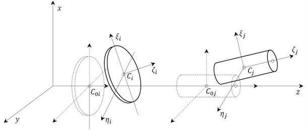
Under consideration was the stationary, global Cartesian coordinate system whose axis “z” coincides with the designed axis of rotation of the machine (Fig. 2). On “z” axis lie geometric centres of rotors, shafts and other rotating components of the system in the undeformed state, at rest. The exception is when these measures are intentionally off-axis due to geometrical imperfections such as bevel shaft axis or coaxiality error.
Other local coordinate systems are hooked in the geometric centers of solids and permanently associated with them. In order to describe the position of each solid six generalized coordinates are used – three translational determining the position of the geometric center of the block in relation to the stationary system and three rotational in the form of three Euler angles (rotation 1-2-3).
Fig. 2Assumed coordinate systems
At the initial stage of the project the possibility of using available in Simulink methodologies of modeling physical systems based on libraries Sim/Scape and Sim/Mechanics [12] was considered. Technology “SimScape” allows creating a network representation – “Physical Network” of any system containing electrical, mechanical, hydraulic components, and other physical objects. Such mechatronic approach to modeling of physical systems is currently very widespread [13].
Due to the complexity of the mathematical description of the motion of the main library element, which is a rigid rotor with six degrees of freedom and the present coupling between translational and rotational motion of the rotor, the final decision was to choose a classic way of modeling in Simulink subsystems and signal flow.
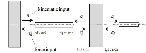
The above decomposition manner of a rotating machine causes that the proposed library gets two basic types of blocks – blocks of Simulink modeling inertial elements and blocks used for modeling sections of shafts. It is assumed that inertial elements will affect elastic elements via kinematic force during the motion. This means that the displacement of the inertial elements will cause deformation of elastic elements. In contrast, elastic elements will influence movement of the inertial elements by forces which result from their elastic properties and the internal damping. Each inertial element is adjacent to one or two elements – shaft sections (Fig. 3).
Fig. 3The idea of signals exchange between Simulink blocks representing: a) elastic and inertial elements and b) a typical wiring diagram
a)

b)
It is sufficient to use six generalized coordinates to describe the position of the rigid inertial element:
Kinematic signal in the library is a concatenation of the signals that determine the position, velocity and acceleration of the inertial element:
The second signal type in the library, generated by the elastic elements is in the form of generalized forces:
4. Block modeling rigid rotor
The main element of the library is an inertial block representing thin rigid rotor (rotating disc). Mathematical model of a thin rigid rotor has been discussed in previous work of the author [14]. The following focuses on the general description of the functional block.
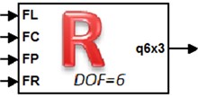
By default, the block has four inputs and one output (Fig. 4(a)). Inputs indicated by symbols “FL” and “FR” are used to introduce “inner” forces originating from neighboring elastic elements, with which the rotor is connected. Inputs “FC” and “FP” allow including external forces acting respectively on the geometric center and center of mass of the rotor. The block output represents the current configuration of the rotor in space.
Typical parameters of a rigid rotor block can be divided into five groups: inertial, describing the imbalance, describing the geometric imperfections, mass forces and initial conditions. It is possible to design an individual menu for each library block that facilitates parameters modification (Fig. 5).
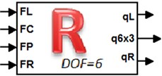
Fig. 4Simulink block representing a) thin rotor and b) long rotor
a)
b)
Fig. 5Expanded pop-up menu of thin rotor block
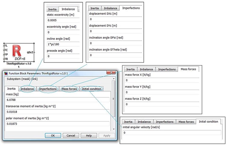
In the case of thin axisymmetric rotor inertial parameters are: mass, polar and transverse mass moment of inertia. Static unbalance can be described specifying eccentricity and its angle. In contrast, the dynamic unbalance is defined by inclination angle the main axis and possibly preceding angle.
Fig. 6Possibility of modeling geometric imperfections
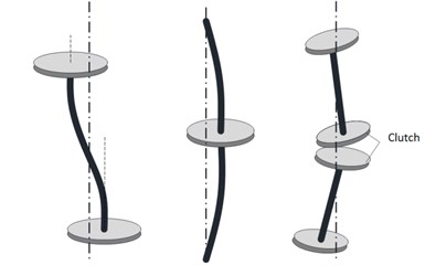
Geometrical imperfections are group of parameters for modeling of machines with rotors displaced and pre-inclined to the axis of rotation (Fig. 6). It is assumed that such displacements do not cause tension (forces) in elastic elements (an example can be fixed bending of the shaft axis).
The last two groups of parameters allow to introduce the mass forces (e.g. gravity) acting on the rotor, and to take into account cases where the machine is pre-dispersed and is in steady state by entering an initial angular velocity of rotation.
Model thin rigid rotor can be easily generalized to the case of a rigid rotor with finite length. Block modeling long rigid rotor will have an additional two outputs representing the displacements its end points (Fig. 4(b)). One can assume that these points are coaxial with the geometrical center, i.e. all three points lie on the axis of rotation. Calculating displacements of end points on the basis of the geometric center movement requires additional parameters – distance of end points from the geometric center. Without loss of generality one can assume that the geometric center and center of mass of the rotor lie on the same cross section of the rotor. In this way, it is not necessary to indicate an additional coordinate for the description of static unbalance.
5. Block modeling elastic shaft
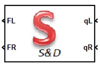
The definition of an elastic element, as a section of the shaft connecting the inertial components is very wide. It requires only that the displacements the ends of the elastic element are quantities known and consistent with the displacements of combined with them the inertial components. In contrast, the force with which elastic element operates on the inertial are to be designated. Thus, a typical elastic block will have two inputs – known displacements, and two outputs – the calculated force (Fig. 7). For the description of the deformation of the shaft just twelve coordinates are used – degrees of freedom (six on each end).
Fig. 7The idea of cooperation of elastic element and a) rigid rotors and b) typical block modeling elastic element

a)
b)
In the simplest case a shaft section can be replaced by elastic-damping element. This means complete omission of the mass of the shaft in the global balance of kinetic energy. This method of the shaft modeling makes it difficult to take into account the boundary conditions – shaft support, especially in case of central supports. Necessary is then a supplementary inertial element, which will model the supported part of shaft and the bearing.
A stiffness matrix of elastic element can be determined by various methods. For example method of forces or beam element matrix can be used.
In a more complex model, the shaft weight can be taken into consideration. One of the proposed methods is to divide the shaft into rigid beam elements and spring-dashpot elements using the rigid finite element method [15]. Alternatively, one can use the classical FEM and the Timoshenko beam model. In both cases, there occur additional internal degrees of freedom, and it is necessary to implement within a block the procedures for the integration of equations of motion.
6. Blocks modeling the bearing, elastic couplings and other elements of the library
Block modeling shaft bearing belongs to a group of inertial elements. In some cases, the introduction of this block to the model is necessary to enable the modeling of the supports. Additionally, the bearing block can also be used for driving the rotating system with a torque.
Typical bearing block has two inputs – forces from coming from elastic elements and one output – the displacement of the bearing. In addition, one can still predict the output that allows to record dynamic forces in the bearing.
Of course it is possible to introduce more complex models of shaft bearing and to include further degrees of freedom. The rule is that there are six basic external degrees of freedom. The associated displacements affect forces generated by the sections of shafts. The remaining degrees of freedom, if they occur in the model, will be considered as internal.
Too detailed modeling of the dynamic phenomena in the bearing is not preferred, because it negatively affects the length of integration step of motion equations of the entire rotating system. Masses of the moving parts in the bearing are very small and stiffness is very large. The frequency of free vibrations the bearing components can be of several orders higher than the frequency of vibration of the rotors. The observed vibratory phenomena are taking place in very different time scales.
Therefore, in simple bearing models it is preferred to include in the equations of rotational, longitudinal and swinging motion reduced masses and moments of inertia of the supported part of shaft. Additionally, in the equations of transverse motion the housing mass, and stiffness and damping of the base should be included.
Different types of connections of shafts, elastic couplings and other couplings such as friction and torsional vibration damper can be modeled using the general concept shown in Fig. 8. Two rigid rotating disks act on each other opposing by forces that depend on their relative positions and the relative movement. These forces are calculated in a special function block. Formulas for the calculation of the forces must be determined on the basis of experimental studies and identification of the coupling parameters. Typically, these are static and dynamic characteristics of elastic and damping coupling properties. Data of this type are difficult to access and generally are not provided in catalogs of couplings manufacturers. Optionally they can be obtained from the specialist literature, e.g. [17, 18].
Fig. 8The idea of modeling an elastic coupling
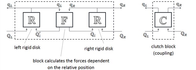
As in the case of the bearing, complexity level of the dynamic model of the coupling can be very different: from simple models which include only some degrees of freedom to models that use two thin rigid rotors with six degrees of freedom each. In terms of functionality, due to the nature of inputs and outputs, block modeling clutch belongs to a group of inertial elements.
In order to simulate machine unsteady states (during start-up, braking, or the presence of loads which cause changes in the speed of rotation) auxiliary blocks generate appropriate time dependent driving signals are necessary. There are two ways to drive the machine: through programmed in the time the driving torque or by kinematic input – with set the angle of rotation, rotational speed and acceleration.
The specificity of the solutions adopted when designing the library causes that torque must be applied to the inertial element: the rotor, bearings, couplings. In contrast, kinematic input can only operate on one of the ends of the shaft – elastic element. Because in kinematic input the remaining degrees of freedom (except rotation) must be zero, so end of the shaft driven in such a way is rigidly mounted on a thrust bearing. It should be noted that in the drive of the rotating machine can also be used ready engine models developed in Simulink and described in the literature such as [18].
7. Numerical example using the library
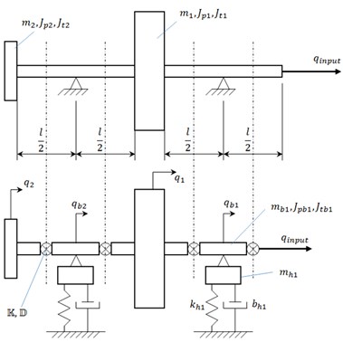
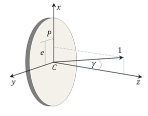
The model of the rotating system containing two spinning thin rigid rotors, mounted on steel solid shaft supported on two self-aligning ball bearings were analyzed (Fig. 9(a)). It was assumed that the main rotor has static and dynamic unbalance. Dynamic unbalance is defined as a deviation of the principal axis of the inertia ellipsoid (Fig. 9(b)). Main parameters of the model are given in Table 1.
Fig. 9a) Scheme of the whirling system and the lumped mass model and b) definition of static and dynamic unbalance
a)
b)
Table 1Main parameters of the whirling system
Part of the system | Parameter description | Parameter value |
Shaft | Diameter | d=0.012m |
Length | l=0.287m | |
Rayleigh’s damping | α=β=0.002 | |
Rotor 1 | Diameter | D=0.157m |
Length | L=0.04m | |
Mass | m=6.0788kg | |
Polar mass moment of inertia | Jp=0.01873kg/m2 | |
Transverse mass moment of inertia | Jt=0.01018kg/m2 | |
Static unbalance | e=0.0005m | |
Dynamic unbalance | γ=1° | |
Rotor 2 | Diameter | D=0.110m |
Length | L=0.04m | |
Mass | m=3.0935kg | |
Polar mass moment of inertia | Jp=0.00485kg/m2 | |
Transverse mass moment of inertia | Jt=0.002837kg/m2 | |
Static unbalance | e=0.00001m | |
Dynamic unbalance | γ=0° | |
Housing | Mass | mh=1kg |
Stiffness | khx=khy=106Nm-1 | |
Damping | bhx=bhy=2∙102Nsm-1 | |
Bearing | Coefficient of friction torque | μd/2=0.002m |
Viscous damping | bψ=bθ=5Nsm-1 |
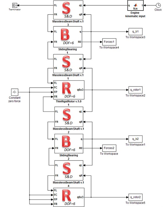
Fig. 10Model prepared in Simulink
The second rotor has a substantially smaller mass in comparison to the main rotor. In some sense the second rotor acts as an inertial vibration damper. On the other hand, it is mounted far away enough from the bearing number two and is susceptible to gyroscopic effects.
The parts of the shaft as elastic-damping elements were modeled. The elastic properties of the shaft part were calculated using the stiffness matrix of a single Bernoulli beam element. Contribution of the mass of the shaft in the global balance of kinetic energy has been omitted. Nevertheless, the matrix of inertia of the beam element is used to define the damping matrix, according to the Rayleigh’s proportional damping model. This means that the mass of the shaft was included in the balance of the damping power loss.
The highly simplified model of a self-aligning ball bearing was adopted. The translational movements in the x and y axis directions the mass of the housing and the stiffness end damping of the suspension were taken into account. The movement of the shaft in the direction of the z axis is blocked by attaching its right end to an immobile engine. The rotary equations of motion included moments of inertia calculated for shaft parts reduced to the centers of the bearings. The rotary motion which is described by coordinate φ, was additionally dampened by friction torque. The swing movements described by coordinates ψ, θ also were damped.
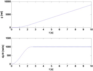
The Simulink’s model of analyzed rotating machine is shown in Fig. 10. The fast startup of a machine to rotational speed equal 1000 rad/s during 2.5 seconds was simulated. It was assumed that the programmed in time rotational speed change can be obtained by controlling the electric motor. The kinematic input was applied to the right end of the shaft. The following formula was used:
where: ωn=1000rad/s, tn=2.5s.
8. Results and discussion
The variable-step solver ode113 (Adams) was selected, with maximum step size 0.001 s. Important data, like displacement of the rotor, were registered in the Simulink workspace with quantization equal to 1 kHz.
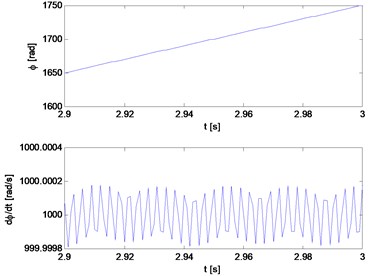
Fig. 11 illustrates the change over time in the rotation angle and the angular speed of the main rotor. Torsional vibrations, causing periodic changes in velocity are visible on the magnification.
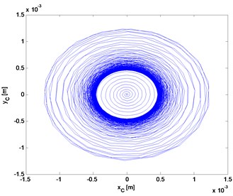
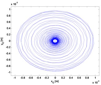
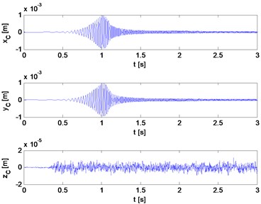
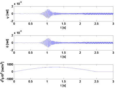
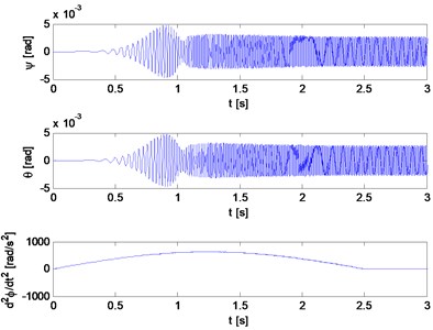
The remaining Figs. 12-20 summarize the results obtained for the main rotor (a) and for the second rotor (b).
Fig. 11Angle of rotation and angular velocity of the main rotor
a)
b)
Fig. 12Trajectory of the geometric center: a) main rotor, b) second rotor
a)
b)
Fig. 12 presents the trajectory of the geometric center of the rotors. Despite of the smaller mass of the second rotor and a 50-times smaller static unbalance, the transverse vibrations amplitude is comparable to the amplitude of the main rotor. This is due to the gyroscopic effect.
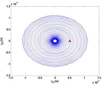
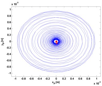
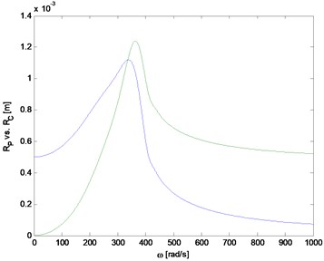
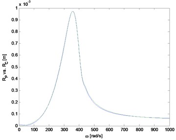
Analysis of the trajectory of the center of mass (Fig. 13) allows observing the phenomenon of self-centering of the main rotor. The triangle represents the location of the center of mass at the beginning of the simulation and the asterisk position after exceeding the critical speed, at the end of simulation. Imbalance second rotor is so small that this effect does not occur. This can be seen also in Fig. 14, which shows the distance of the geometric and mass center from the axis of rotation, depending on the rotation speed.
Fig. 13Trajectory of mass center
a)
b)
Fig. 14The distance from the axis rotation of the geometric center and center of mass
a)
b)
Fig. 15Flexural and longitudinal vibrations
a)
b)
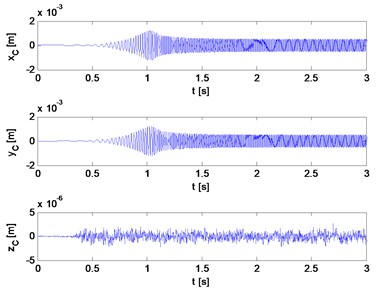
Transverse and longitudinal vibrations, inclinations of the plane of the disc rotation (gyroscopic effects) are shown in Figs. 15 and 16. As might be expected, vibrations of the second rotor described by angles ψ, θ are larger.
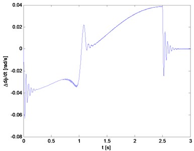
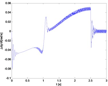
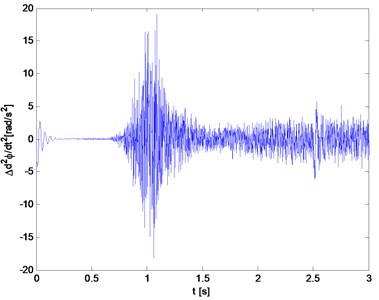
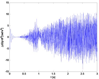
Fig. 17 and Fig. 18 show the difference between the rotating speed (acceleration) of a rotor and speed (acceleration) of the drive. These are the speed and acceleration of the torsional vibrations. Torsional vibrations of the main rotor disappear faster than the second rotor. While crossing a critical state the rotors are braking and next would rapidly increase the speed in relation to the drive.
Fig. 16Inclinations of the planes of rotation and rotational accelerations of rigid rotors
a)
b)
Fig. 17Difference between the velocities of the rotors and the speed of the drive
a)
b)
Fig. 18The difference between the accelerations of the rotors and the acceleration of the drive
a)
b)
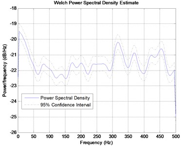
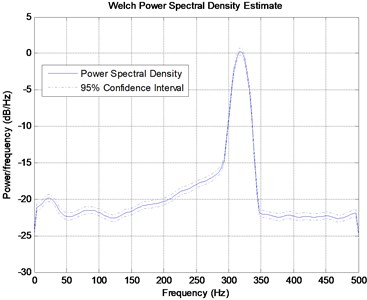
In Fig. 19 is shown the power spectral density of the acceleration signal of torsional vibrations. Ready-made tools (PSD) available in Matlab and the entire recorded 10 seconds of the signal were used.
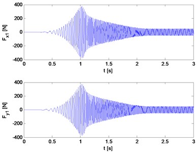
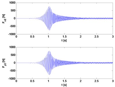
The shaft is mounted on self-aligning flexible bearings, which changes the characteristics of critical states and the form of vibrations. The vibrations in the bearings can be observed by forces waveforms (Fig. 20).
Fig. 19Power spectral density from signals shown in Fig. 18
a)
b)
Fig. 20Forces in the bearings
a)
b)
9. Conclusions
The library of Simulink blocks described above is during development. It is continuously improved and tested. Presented method of modeling of rotating systems is an alternative to existing systems based on FEM. However, it was conceived primarily as a tool for theoretical investigations and simulation in the field of transient analysis, coupled flexural and torsional vibrations and highly nonlinear cases. It cannot compete with professional systems that are more convenient for applications in practical issues such as the designation of critical states. Its advantage is the relatively small number of degrees of freedom which reduces simulation time and allows the study of non-steady states with low cost of computer hardware. Another advantage is ability to easily integrate with tools and models available in Simulink and Matlab.
In the nearest future authors plan to use presented models to evaluate methods of active damping of torsional vibrations. The library can also be used to prepare machines models necessary in the systems to monitoring and diagnostics of the vibrations (such as for example marine gas turbine engines [19] and for passenger cars [20-24]).
The above example of modeling simple rotating system allows evaluating the suitability and possibilities of the Simulink library developed by the authors.
References
-
Prohl M. A general method for calculating critical speeds of flexible rotors. Journal of Applied Mechanics, Vol. 12, Issue 3, 1945, p. 142-148.
-
Mackerle J. Finite element computational dynamics of rotating systems. Shock and Vibration, Vol. 6, Issue 4, 1999, p. 209-222.
-
Genta G. Dynamics of Rotating Systems. Springer, New York, 2005.
-
Kiciński J. Rotor dynamics. Publisher IMP PAN, Radom, 2006.
-
Chen W. J., Gunter E. J. Dynamics of Rotor Bearing Systems. Victoria, Canada, Trafford, 2007.
-
Thieffry P., Jandric D. Turning to rotordynamics. Tools from ANSYS work together to optimize rotating parts. ANSYS Advantage, Vol. 4, Issue 2, 2010.
-
Rotordynamics with ANSYS Mechanical Solutions. Tutorial, http://www.ansys.com.
-
Sellgren U. Component mode synthesis – a method for efficient dynamic simulation of complex technical systems. Technical Report, Dep. of Mach. Design, The Royal Institute of Technology. Stockholm, Sweden, 2003, p. 26.
-
Wagner M. B., Younan A., Allaire P., Cogill R. Model reduction methods for rotor dynamic analysis: A survey and review. International Journal of Rotating Machinery, Vol. 2010, p. 17.
-
Łazarz B., Matyja T. Simulation of the non-steady states in rotating power transmission systems with use of Simulink. 20th International Congress on Sound and Vibration, Bangkok, Thailand, 2013.
-
Matyja T. Simulink library project for modeling and simulation of dynamic phenomena in rotating power transmission systems. International Scientific Conference of Transport Problems, 2013.
-
SimScape User’s Guide. SimMechanics User’s Guide. The MathWorks, Natick, MA, 2008.
-
Janschek K. Mechatronic System Design. Methods, Models, Concepts. Springer, NY, 2012.
-
Matyja T. Model of stiff rotor with six degrees of freedom. 20th International Congress on Sound and Vibration, Bangkok, 2013.
-
Wittbrodt E., Adamiec-Wójcik I., Wojciech S. Dynamics of Flexible Multibody Systems: Rigid Finite Element Method. Springer, 2007.
-
Opasiak T. The study of the basic parameters of flexible couplings. Advances in Science and Technology, Reviewed Journal – Quarterly, Technical University of Lublin, p. 122-130, (in Polish).
-
Sładkowski A., Opasiak T. FEM model of flexible coupling ASR type. Transport Problems, Vol. 2, Issue 3, 2007, p. 107-114.
-
Margielewicz J., Haniszewski T., Gąska D., Pypno C. Model studies of the lifting mechanisms of overhead traveling cranes. Committee on Transport, PAN, Katowice, 2013, (in Polish).
-
Grządziela A. Analysis of vibration parameters of ship gas turbine engines. Polish Maritime Research, Vol. 2, 2006, p. 22-26.
-
Burdzik R., Folęga P., Łazarz B., Stanik Z., Warczek J., Analysis of the impact of surface layer parameters on wear intensity of friction pairs. Archives of Metallurgy and Materials, Vol. 57, Issue 4, 2012, p. 987-993.
-
Burdzik R., Konieczny Ł., Figlus T. Concept of on-board comfort vibration monitoring system for vehicles. Activities of Transport Telematics, Vol. 395, 2013, p. 418-425.
-
Konieczny Ł., Burdzik R., Figlus T. Possibility to control and adjust the suspensions of vehicles. Activities of Transport Telematics, Vol. 395, 2013, p. 378-383.
-
Burdzik R. Monitoring system of vibration propagation in vehicles and method of analysing vibration modes. Communications in Computer and Information Science, Vol. 329, 2012, p. 406-413.
-
Burdzik R., Stanik Z., Warczek J. Method of assessing the impact of material properties on the propagation of vibrations excited with a single force impulse. Archives of Materials and Metallurgy, Vol. 57, Issue 2, 2012, p. 409-416.
About this article
The results presented in the paper were obtained within supported by the Polish Scientific Committee.
