Abstract
In this paper, the FLUENT and KULI soft wares were used to analyze the cooling performance on the radiating module of the cooling system for a heavy vehicle by 1D/3D coupling simulation. According to the analysis, the cooling performance of the existing engine cooling system for heavy vehicles is declined by the gap between the intercooler and radiator in the cooling system. Moreover, the structure of an integrated cooling system was proposed. The wind tunnel experiment model was built in the FLUENT software to analyze the original cooling system and the integrated cooling system by three-dimensional simulation. Then the obtained velocity matrix from 3D simulation was imported into the KULI software to compare the cooling performances of the original system and the integrated system. It was found that the cooling performance of the integrated cooling system is superior to that of the original cooling system.
1. Introduction
The cooling system is one of the important auxiliary systems to ensure the normal and stable operation of heavy vehicle engine. Its main goal is transferring part of the heat generated by the combustion in the engine from the inside to the outside. And it is to ensure that the engine and the each heated part in the engine compartment works at the most appropriate temperature [1]. However, a lot of car enterprises design increasingly small engine compartment for less energy consumption and sufficient cabin space. And for heavy vehicles, the matching between radiator groups in the engine compartment and the layout of other spare parts will directly affect the cooling performance of cooling system. Therefore, under the circumstances of limited space and bad heat dissipation conditions, it has become an inevitable trend to design a radiating module that not only have adequate cooling capacity and strength but also guarantee high cooling efficiency and low energy consumption for the cooling system [2, 3].
Traditional design is to carry out the wind tunnel test after the original model is produced, which has a disadvantage of long development cycle and high cost. With the development of computer technology, one-dimensional and three-dimensional soft wares are widely used in the field of automotive thermal management [4, 5]. The KULI software is one-dimensional software for the design and simulation of vehicle thermal management, and developed by the STEYR engineering technology center. It considers systematically the performance match between different components and between components and system. However, it assumes that the cooling wind speed is evenly distributed on the surface of the radiator. The truth is that it is not evenly distributed due to the air flow field, which will have an impact on the accuracy of the results. The FLUENT software is a comparatively popular commercial CFD software package, which is able to simulate the distribution of the three-dimensional flow field and obtain the wind speed distribution on the surface of the radiator by post-process. Considering the respective advantages and disadvantages of the 1D and 3D software, the velocity matrix of the radiator is obtained by analysis in FLUENT and imported into KULI to simulate the heat dissipation of the cooling system. The influence of the different gap between the intercooler and radiator in the engine cooling system on the cooling performance was compared, and a new radiating module integrating the intercooler and radiator is designed according to the results of the simulation [6].
2. Three-dimensional analysis of the radiating module
2.1. Simplified calculation model
2.1.1. Wind-tunnel model
This paper focuses mainly on the influence of different relative positions of the intercooler and radiator in the radiating module on the cooling performance. Therefore, only a simulation of the relative positions of various components of the radiating module in the wind tunnel test model is needed to analyze its influence on cooling performance, rather than the 3D model of the overall vehicle, which saves much time and does not affect the reliability of the conclusion [7]. The wind tunnel test model built in the SolidWorks is shown in Fig. 1, and its model parameters are listed in Table 1.
Fig. 1Wind-tunnel model
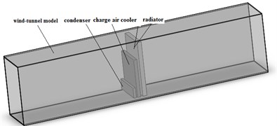
Table 1The model parameters
Component | Length | Width | Height |
Wind tunnel | 3000 | 440 | 690 |
Radiator | 50 | 400 | 650 |
Charge air cooler | 40 | 400 | 450 |
Condenser | 35 | 400 | 120 |
Units: mm | |||
2.1.2. Computational grid
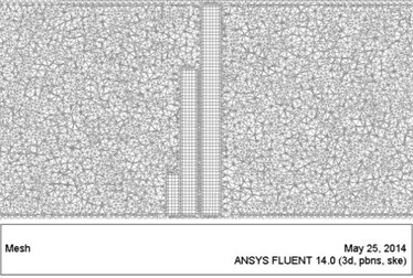
To improve the calculation accuracy, it is an import work to divide the grid in the areas where the surface flow parameters of the condenser, intercooler and radiator change dramatically [8]. The grid mesh is done in the Gambit software and shown in Fig. 2, the radiating module taking the Hex grid form and the fluid domain taking the Tet/Hybrid grid form.
Fig. 2Gird division on the plane of y= 0
2.1.3. Porous medium model
The core of radiator and intercooler in the cooling system is composed of a large number of heat pipes and radiating fins structures. So its structure is very complicated. It will greatly exceed the computing ability of normal computers if these details are fully considered in the FLUENT software. Therefore, it is necessary to simplify the radiator and intercooler core model and so far a widely-used simplified model is the porous medium model [9].
When the core of the condenser, intercooler and radiator is processed as porous media region, it is easy to calculate the pressure loss when the cooling air passing through the radiating module. On the simple and uniform porous medium, Darcy’s law of porous media can be used as the mathematical model, namely:
where α represents the permeability factor of porous medium; C3 refers to the inertial resistance factor; μ indicates viscosity coefficient, whose value is 1.7894×10⁻⁵.
The coefficient of porous media can be calculated by trial and error method according to the test data of the wind speed and pressure drop provided by the supplier. The porous medium parameters in this paper are shown in Table 2.
Table 2The porous medium parameters
Conditions | Inertia resistance coefficient A | Viscous resistance coefficient B |
Condenser | 2.89×10⁷ | 203.78 |
Charge air cooler | 2.03×10⁷ | 259.42 |
Radiator | 5.09×10⁷ | 184.32 |
2.1.4. Boundary conditions
Fluent analysis was conducted in a limited area; it is required to confirm the boundary conditions. The determination of boundary conditions is needed to meet well-posed ness. In this paper, the cold flow field (external flow field) and hot flow field (internal flow field) in the radiating module were analyzed respectively in the FLUENT and the KULI. Therefore, it was no necessary to consider the heat transfer boundary conditions in the FLUENT software. And three flow boundary conditions (velocity-inlet, pressure-outlet, wall) and boundary condition of porous media were enough for the analysis, among which the velocity-inlet was 12 m/s, the pressure-out was 101325 Pa and the wall was adiabatic wall.
2.2. Results and discussion
Fig. 3The distribution of velocity streamlines
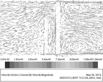
a) When the gap is 20 mm
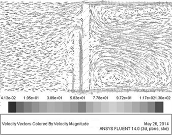
b) When the gap is 8 mm
The divided grid in the Gambit was imported into the FLUENT, and post-processing was done. The air flow conditions can be easily obtained by calculation and are shown in Fig. 3(a) and Fig. 3(b).
The Fig. 3 shows that, the amount of the air which flows into the gap from above when the gap between intercooler and radiator is 20 mm is obviously larger than that when the gap is 8 mm. It makes the amount of air which goes directly through the intercooler greatly reduce. This reason is that, the intercooler and the radiator is not completely overlapping and there is a gap between them, which makes the pressure of the cooling air between the intercooler and radiator is lower than that in the non-overlapping portions on the side surface, and thus the cooling air in non-overlapping portions will cross into the overlapping space. As a result, the air pressure of the overlapping space increases, the air pressure difference between inlet and outlet of the intercooler reduces, the amount of air through the intercooler greatly reduces and the cooling effect of pressurized air is seriously weakened. At the same time, it has a bad influence on the radiating performance of the whole cooling system.
The Fig. 4 shows the velocity distribution contours, which indicates visually the velocity distribution in the entire flow field. Comparing Fig. 4(a) with Fig. 4(b), it is found that the smaller gap between the intercooler and the radiator is, and the more uniform the velocity distribution on the surface of the radiator is. Moreover, the maximum of the velocity under the condition of small gap is also greater than that of large gap.
Fig. 4The velocity distribution contours
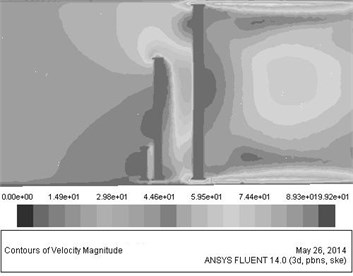
a) When the gap is 20 mm
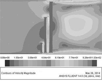
b) When the gap is 8 mm
By the three-dimensional analysis of the radiating modules with different gaps, it is obtained that the velocity of the cooling air through the entire radiating module will be more uniform with the air flow rate becoming larger, when the gap between intercooler and radiator becomes smaller.
3. One-dimensional/three-dimensional coupling analysis of radiating module
When the cars thermal management analysis is done in the KULI, it assumes generally the cooling air on the surface of the heat-radiating part is evenly distributed. However, it can be seen from the analysis results that it is not evenly distributed due to the difference gap. According to the radiating principle of the heat-radiating parts and the theory of heat transfer, the cooling wind speed has a great influence on the cooling performance of the entire system. The error may be large if the thermal analysis is done only by the KULI. In this study, 1D and 3D coupling simulation was used for the analysis of the influence of different gaps on the cooling performance of the radiating module.
3.1. The settings of engine cooling system parameters
The main technical parameters of the engine used in this paper are shown in Table 3.
Table 3The main technical parameters of engine
Intake form | TCI (Turbo Charger with Inter-cooler) |
Number of cylinders | 6 |
Bore×Stroke (mm) | 120×130 |
Displacement (L) | 8.8 |
Rated speed (r⋅min-1) | 2100 |
Rated power (KW) | 275 |
Maximum torque (N⋅m) | 1550 |
The maximum torque speed (r⋅min-1) | 1300 |
According to the structure form of the heavy vehicle engine compartment, the model of the import pressure drop(CP valve in the KULI), grid resistance, intercooler, radiator, mechanical fan, the internal pressure drop(internal resistance in the KULI) and the outlet pressure drop was built in the KULI. The performance characteristics of the intercooler, radiator and fan were provided by the supplier, while the amount of released heat and circulating water were obtained by the calculation above. The air side model of the cooling system is shown in Fig. 5.
Fig. 5The air side model of the cooling system
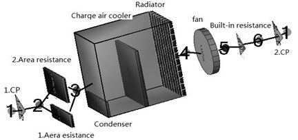
3.2. 1D/3D coupling analysis
Considering the influence of the uneven temperature distribution on the radiator surface, the radiator was divided into discrete small pieces (shown in Fig. 5), and the surface velocity of every small piece can be substituted into by the velocity matrix obtained in the FLUENT, which will guarantee higher accuracy of the calculation result [10].
Fig. 6The velocity distribution of the radiator surface
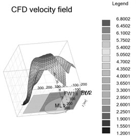
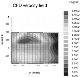
Fig. 7The air side model of the cooling system after adding resistance matrix
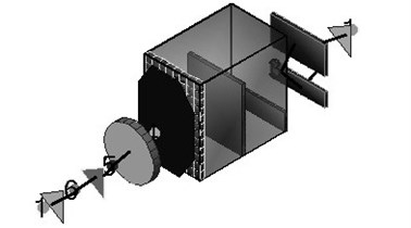
Under the same conditions, the velocity matrix was imported into the KULI, and converted into corresponding resistance matrix at the same time. The Fig. 6 shows the velocity distribution of the radiator surface by imported from the FLUENT into the KULI. Fig. 7 shows the air side model of the cooling system after adding resistance matrix in the KULI.
From the velocity distribution contours on the radiator surface in Fig. 6, it can be seen that the velocity of the radiator surface is evenly distributed by default without considering the influence of other components in the cooling system on the cooling air, which is obviously not consistent with the actual situation. However, when the analysis results in the FLUENT are imported into the KULI, the velocity distribution of the radiator surface is not uniform any longer, and a comprehensive result of considering the influence of other components and the gaps between them can be obtained.
3.3. Simulation results
The simulation parameters of digital model, mainly including engine speed, mean value of effective pressure, simulation driving speed, air humidity and pressure, are confirmed according to bench test data and the component model parameters. The radiating module is investigated under the conditions that the gap between intercooler and radiator is respectively 20 mm and 8 mm.
Through the simulation analysis in the KULI, main result data are obtained (shown in Table 4), including the inlet and outlet temperature of the radiator and the temperature difference, inlet and outlet temperature of the intercooler and the temperature difference.
Comparing the temperatures of intercooler and radiator when the gap between them are respectively 8 mm and 20 mm, it is concluded that the export water temperatures of both the intercooler and the radiator are in the allowed temperature range, when the clearance is 8 mm (it is generally believed that the allowed temperature of the cooling water for heavy vehicle engines is between 85°C and 95°C, and the engine inlet temperature is around 50°C). Moreover, the water and air temperature differences of the inlet and outlet are greater than that when the gap is 20 mm. Therefore, it is a reasonable hypothesis that the smaller the gap between the intercooler and the radiator is, the better the cooling performance of them will be.
4. Integrated radiating module
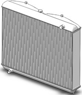
According the 1D/3D coupling analysis above, the gap between the intercooler and the radiator has a certain influence on the cooling performance of the radiating module, namely when the gap is smaller, the cooling performance is better. On basis of it, a new structure of an integrated cooling system was proposed in this paper (see Fig. 8). The characteristics of this structure are as follows: the traditional intercooler and the radiator are made into a whole, which is equipped with cooling gas pipes and cooling liquid pipes at the same time. When the cooling air goes through the structure, it can act as an intercooler and a radiator at the same time. The whole cooling device has the advantages of high radiating efficiency, low noise and small size, etc [6].
Fig. 8An integrated cooling system
A similar 1D/3D coupling method was taken to simulate and analyze the integrated structure in the FLUENT. Fig. 9 shows the distribution of velocity streamlines, and Fig. 10 shows the distribution contours of velocity value.
The velocity matrix obtained in the FLUENT was imported into KULI in the same way. The air side model in the KULI will not be described here due to the limited space. Under the same simulation parameters, the simulation results are shown in Table 4.
Fig. 9The distribution of velocity streamlines
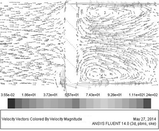
Fig. 10The distribution contours of velocity value
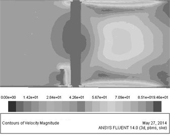
Table 4Simulating results
The gap between intercooler and radiator [mm] | 8 | 20 | Integrate | |
Radiator | Entry temperature [°C] | 92.47 | 100.83 | 92.02 |
Exit temperature IM [°C] | 87.19 | 96.53 | 85.21 | |
Temperature difference IM [°C] | 5.28 | 4.30 | 6.81 | |
Charge air cooler | Entry temperature [°C] | 140.42 | 148.95 | 139.45 |
Exit temperature IM [°C] | 46.63 | 62.36 | 45.32 | |
Temperature difference IM [°C] | 93.79 | 86.59 | 94.13 | |
By comparison of the results and earlier results, it can find that its cooling performance is superior to traditional radiating module. Because it is not influenced by the gap and the air flow rate on the surface of the radiating parts is relatively even.
5. Conclusion
This paper mainly focuses on the radiating module of engine cooling system for a heavy vehicle, and the influence of the gap between the intercooler and the radiator on the cooling performance of the whole radiating module was explored in the virtual wind tunnel model by the 1D/3D coupling method. Theoretical and simulation results show that the gap between the intercooler and the radiator has a certain influence on the cooling performance. When the gap is smaller, the cooling performance of the radiating module is better. A new integrated cooling system was designed according to the results. This structure has better cooling performance than traditional cooling systems with the advantages of high radiating efficiency, low noise and light weight, etc.
References
-
Wei Q. G., Su T. X., Dong X. R. Automabile engine structure and principle. Beijing, National Defence Industry Press, 2012, p. 139-151.
-
Fortunato Francesco, Damiano Fulvio, Matteo Luigi Di, et al. Underhood cooling simulation for development of new vehicles. SAE Paper 2005-01-2046.
-
Yuan X. Y., Gu Z. Q., Yang Y., et al. Numeriacl simulation on vehicle underhood cooling. Automotive Engineering, 2009, p. 843-847.
-
Beier M., Seider G. Numerical sensitivity study on the prediction of rasiator perfomance using CFD underhood airflow simulation. 4th Conference of Vehicle thermal management systems, 1999, p. 769-786.
-
Gu N., Ni J. M., Zhong Y., et al. Parameters setting parameters and simulation of transient state model in engine thermal management based on KULI. Journal of Computer Application, Vol. 29, Issue 7, 2009, p. 1963-1965
-
Long Y. H., Li W. S., et al. An integrated cooling system. China patent, ZL201320756275.9, 2014 April 30.
-
Zhang B. Y. Research on Automotive Compact Cooling System. Guandong University of Technology, 2012.
-
Zhang K., Wang Y. Zh., Yang X. Y. Improving underhood cooling performance by using CFD technique. Automotive Engineering, 2011, p. 314-317.
-
Kita-ku SC/Tetra V8 User’s Guide: Solver Reference. Japan, Software are Gradle Co. Ltd., 2009.
-
Hömann T., Lechner B., Puntigam W. Numerical and experimental investigation of flow and temperature fields around automotive cooling systems. SAE paper 2005-01-2006.
About this article
This project was funded by the Project of National Natural Science Foundation of China (Grant No. 51165003), Guilin Scientific Research and Technology Development Research (Grant No. 20120102-1), the Project of Liuzhou Scientific Research and Technology Development Research (Grant No. 2013H020401) and the Director subject of Guangxi Manufacturing Systems and Advanced Manufacturing Technology Laboratory (Grant No. Gui Branch Neng 11-031-12_009).
