Abstract
Simple and effective new type of tactile device is presented and investigated, which transfers 2D graphic information to the visually impaired people. It consists of piezoelectric bimorph cantilever, acting as an oscillating probe, and, when changing operational signal, could transfer information to visually impaired people, e.g. by crossing the lines/contours on the screen of tablet PC or determining the color of them. Determining the amplitude of tip’s oscillation, attached to bimorph PZT cantilever and contacting with finger, is presented. It is established that tactile device’s body and integrated bimorph cantilever oscillations and their effect on the human finger are different. The visually impaired people better percept the oscillations of Braille pins, which are attached to cantilever tip; maximum perception of tip’s oscillations are achieved, when bimorph tip generates approximately 0.5 N force.
1. Introduction
A lot of research activity today is devoted to developing touch sensing systems, exploiting different effects and materials: electromechanical, piezoelectric, magnetostrictive, etc. All these materials are described as smart materials. Using smart materials provides the possibility to create small, effective and usable tactile device that could transfer varied kind of information. Many systems are developed for visually impaired people; plenty of them are using matrix of Braille pins. Some of these devices are based on the application of piezoelectric cantilevers [1-3]. The pins could simulate Braille letters and are based on changing the surface of finger touching area.
In this paper we present new type of tactile device, which exploits the specific properties of piezoelectric bimorph cantilever. It consists of piezoelectric bimorph cantilever, acting as an oscillating probe, and, when changing operational signal, could transfer different information to visually impaired people, e.g. crossing the lines/contours or determining the color of lines or background.
2. The oscillating tip of the bimorph piezoelectric cantilever
In the experiment we used piezoelectric cantilever, developed by Johnson Matthey Catalyst GmBH (Germany); the technical parameters are presented in Table 1. The Fig. 1 represents structure of piezoelectric cantilever.
Fig. 1 presents piezoelectric cantilevers ε0 (strain that defines the bending); it can be expressed by Eq. (1) with the equilibrium condition ∑F=0; ∑M=0 for no external loads. For the complete triple-layer bender [6, 11]:
where:
Fig. 1Structure of the piezoelectric cantilever
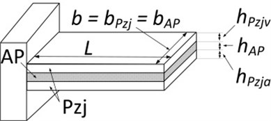
Table 1Johnson Matthey bending actuators’ typical characteristic values [4, 5]
L=0.038 m; | sAP11= 1/ EAP= 14.29∙10-12 m2/N; |
b=0.0072 m; | E3=U2hpzj= 57.692∙103 V/m; |
hPzj= 0.00025 m*; | h= 0.0008 m; |
hAP= 0.00030 m*; | ε33= 4500; |
d31= –315∙10-12 C/N; | ρPzj= 8.10∙103 kg/m3; |
sPzj11= 14.20∙10-12 m2/N; | ρAP= 1.60∙103 kg/m3; |
EPzj= 1/ sPzj11= 70.423∙109 N/m2; | U= 30 V; |
EAP= 70∙109 N/m2; | |
*the exact parameters are not known (manufacturer’s commercial secrecy). All data are given by experimental measure. | |
Piezoelectric cantilevers’ strain value is calculated by Eq. (1); applied voltage is 30 V. The voltage is sufficient to provide wide range of amplitude of cantilever tip. The strain value is:
The theoretical cantilever‘s deflection is calculated multiplying strain value by cantilever length (parameter L value). Tip deflection value is:
With symmetric bimorph of the length L and the layer thickness h, clamped on one side, the deflection of the free end, calculated with Eq. (3), becomes (with E3=V/2 h):
And finally:
All these calculations were made taken into account equilibrium condition ∑F=0; ∑M=0 for no external loads. The piezoelectric cantilever’s tip can be loaded by force (for example, human touch). This force can be calculated by Eq. (4) and this value will represent the blocking force. If this force will be applied to the cantilever’s tip, the deflection of tip will be 0.
Following Yao piezoelectric actuator’s expression [7, 12], the blocking force could be calculated by:
The blocking force of piezoelectric cantilever, calculated by Eq. (4):
This parameter shows that human finger, developing force 60 mN, will stop cantilever from bending.
3. Experimental results
3.1. Tactile pen design
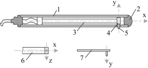
The main characteristics of piezoelectric plate are shown in Table 1. The device is designed using stylus pen. Piezoelectric bimorph cantilever is mounted inside it, so that the free end of cantilever is placed near pen tip. Fig. 2 is showing scheme of tactile probe.
Fig. 2Piezoelectric probe : 1 – body, 2 – touch screen sensitive tip, 3 – piezoelectric bimorph cantilever, 4 – cantilever tip, 5 – Braille pin, 6 – bimorph cantilever view from top, 7 – bimorph cantilever view from side
3.2. Research of piezoelectric bimorph cantilever
The tip’s oscillations were determined using KEYENCE Laser Displacement Sensor LK-G82 [8], (Fig. 3).
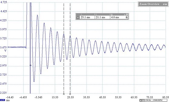
Resonant frequency was found by impact test and is 250 Hz (Fig. 4).
Fig. 3General view of experimental set-up: 1 – tactile piezo bimorph cantilever; 2a – laser sensor head, 2b – laser sensor controller; 3a – Pico Scope 3202 device, 3b – PC with Pico Scope software; 4 – signal generator; 5 – signal amplifier
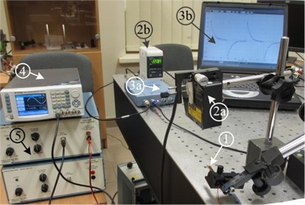
Fig. 4Piezo cantilever’s impact test (F= 250 Hz)
Earlier research established that operator could feel oscillations of the tip with frequency from 5 to 300 Hz [9]. Resonant frequency is near this maximal value, so testing could be done up to this frequency.
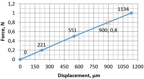
The cantilever coefficient of elasticity was established using laser for measuring the displacements and external force – to load cantilever. The test results are presented in Table 2.
Table 2Piezoelectric bimorph displacement for different force
Force, N | 0 | 0.2 | 0.5 | 1 |
Displacement, µm | 0 | 221 | 551 | 1134 |
Braille pins are sticking out about 0.5 mm [10]. Bimorph cantilever deflection of 0.5 mm is generated by 0.5 N force. To define what control signal parameter should be, we have to calculate stiffness k of the cantilever; in our case k=888.889 N/m (Fig. 5).
Fig. 5Displacement of tip in relation to applied force
3.3. Piezoelectric cantilever’ oscillation effects on tactile probe body
In this research we used scanner of Polytec Laser Vibrometer and the probe with lower resonance frequency due to bigger effective length of cantilever.
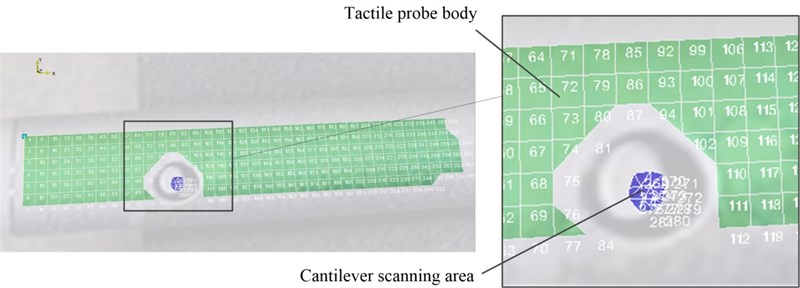
Probe’s body is made from aluminum alloy; the diameter is 8.5 mm, length – 122 mm. Scanned area was ¼ off tactile probe body, where user holds it. Area was about 30 mm length from tactile probe’s end. Fig. 6 show scanning area, divided in 281 finite number of elements. Green color is probe’ body, blue – cantilever Braille pin. The investigated piezoelectric cantilever probe was excited with harmonic signal of 2 Vpp voltage and frequency range between 0 Hz to 10 kHz.
Fig. 6Tactile probe body and cantilever scanning area
From the frequency response presented in Fig. 7, the piezoelectric cantilever has several resonance frequencies. The first resonant frequency is 168 Hz. The second resonance at 1 kHz is highest, but it could be neglected, because the operating frequency range is 15-500 Hz. Operating frequency range was chosen experimentally.
Fig. 7Frequency response of probe’s body in the range of 0-10 kHz and driving voltage 2 Vpp
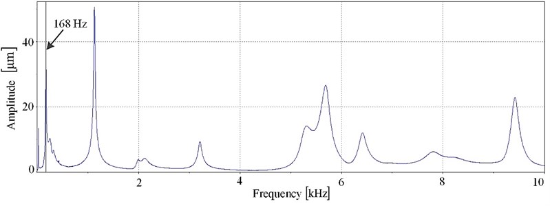
The first resonant frequency of 168 Hz of the cantilever is in the operating frequency range and the amplitude of the cantilever oscillations is 32 μm at the 2 Vpp.
This investigation helps us to find out the oscillation amplitudes of probe’s body and cantilever Braille pins’ displacements. Probe’s body amplitude can be evaluated in tens of nanometers, while cantilever Braille pins – in the order of micrometers.
4. Conclusion
This research describes how to calculate the deflection of bimorph piezoelectric cantilever, used in new design of tactile device, transferring information by changing frequency of oscillation in relation to color of lines or background. The amplitudes of cantilever and probe’s body oscillations are very diverse and operator better percept the oscillations of Braille pin, attached on bimorph piezoelectric cantilever tip.
References
-
Kyung Ki-Uk, Seung-Woo Son, Dong-Soo Kwon, Mun-Sang Kim Design of an integrated tactile display system. Proceedings of the 2004 IEEE International Conference on Robotics & Automation New Orleans, 2004, p. 776-781.
-
Takeshi Hommal, Shuichi Ino, Hayato Kuroki, Takashi Izumi, and Tohru Ifukube Development of a piezoelectric actuator for presentation of various tactile stimulation patterns to fingerpad skin. Proceedings of the 26th Annual International Conference of the IEEE EMBS San Francisco, USA, 2004, p. 1-5.
-
Yiru Zhou, Masahiro Ohka, Tetsu Miyaoka A tactile display presenting pressure distribution and slippage force. Symposium on Haptic Interfaces for Virtual Environments and Teleoperator Systems, Nevada, 2008, p. 13-14.
-
Johnson Matthey Catalysts Overview of bending actuators – typical characteristic values. http://www.piezoproducts.com/fileadmin/user_upload/pdf/jm_piezoproducts_datenblatt_biegewandler_en_02_07_2013.pdf
-
Johnson Matthey Catalysts Bending actuator.
-
http://www.piezoproducts.com/fileadmin/user_upload/pdf/jm_piezoproducts_funktionsweise_biegewandler_en_01_04_2009.pdf
-
Smits J. G., Ballato A. Dynamic admittance matrix of piezoelectric cantilever bimorphs. J. Microelectromech, Vol. 3, 1994, p. 105-12.
-
Qing-Ming Wang, Eric Cross L. Performance analysis of piezoelectric cantilever bending actuators. Ferroelectrics, Vol. 215, Issue 1, 1998, p. 187-213. http://dx.doi.org/10.1080/00150199808229562
-
Keyence High-speed, high-accuracy CCD laser displacement sensor (LK-G series) specifications. http://www.keyence.com/products/measure/laser/lkg/lkg_specifications_3.php
-
Bansevičius Ramutis Petras, Žvironas Arūnas, Gudauskis Marius Investigation of control signal of tactile device with electromagnet. 7th international conference of Mechatronic Systems and Materials, 2011, p. 244-245.
-
Mami Tanaka, Kaoru Miyata, Tatsuo Nishizawa, Seiji Chonan Development of a tactile sensor system for reading Braille: fundamental characteristics of the prototype sensor system. Smart Mater. Struct., Vol. 14, 2005, p. 483-487. http://iopscience.iop.org/0964-1726/14/4/004/
-
Dunsch R., Breguet J. M. Unified mechanical approach to piezoelectric bender modeling. Sciencedirect, Sensors and Actuators.
-
http://www.sciencedirect.com/science/article/pii/S0924424706004365
-
Yao L., Zhang J., Lu L., Lai M. Nonlinear static characteristics of piezoelectric bending actuators under strong applied electric field. Sensors and Actuators, Vol. 115, 2004, p. 168-175.
About this article
This work has been supported by Lithuanian Agency for Science, Innovation and Technology (MITA), Project TactileApps, No. 31V-38.
