Abstract
In this paper, based on the previous research experiences in the lumped parameter modeling and study of active control mounts (ACM) model, an analytical model of active ACM in powertrain is developed and implemented in MATLAB. In order to validate this newly developed model in this work, a finite element analysis (FEA) method is conducted in ANSYS and the results of FEA is compared with analytical model for validation. After the validation, the control strategy is integrated into the analytical model by using the linear quadratic regulator (LQR) method. Numerical results show a good control performance. Furthermore, this work examines the application of genetic algorithms (GA) in optimizing the weight matrices of LQR. An optimal configuration is obtained and thus this approach could help the practical design of ACM systems.
1. Introduction
During the last decade, the noise, vibration and harshness (NVH) has received attention in several publications. As a result, engine mounts are becoming more important as being not only engine vibration isolation but also a part of engine support. One of the main functions of the automotive vehicle engine mounting system is to support the engine body and provide comfort ride for passengers by reducing vibration caused by engine excitation. There is much literature in which extensive investigations have been conducted on different kinds of engine mounting systems, from elastomeric to hydraulic mounts, from passive to semi-active and active mounts.
Although elastomeric mounts have been successfully used for automotive industry for many years, but the conventional elastomeric mounts do not meet all the requirements, it just can only provide a small dampingand a solution between static deflection and vibration isolation [1]. Hydraulic engine mounts (HEM) can offer a better performance than traditional elastomeric mount in the low frequency. Hydraulic mounts have been promising alternatives to conventional elastomeric mounts because of their ability to create frequency-dependent damping.
Hydraulic mounts have been used in the automotive industry since 1985 in General Motors (GM). Today, almost all passenger cars are installed hydraulic mounts. The basic idea of the hydraulic mounts is to use highly elastic rubber for vibration isolation and to use a hydraulic device (inertia track and decoupler) to generate the large damping at a constant frequency for vibration control. The lumped parameter of a floating-decoupler type hydraulic mount (the most common) is as illustrated in Fig. 1, and consists of two fluid-filled chambers separated by a metallic plate containing the decoupler and inertia track. Kr and Br are the equivalent stiffness and damping of the rubber spring. The volumetric compliance of the upper chamber and lower chamber are modeled as C1 and C2. Also, the pressures in the upper and the lower chambers are captured by P1 and P2. Ap is the effective piston area, and the flow through the inertia track Qi and the decoupler Qd. Ii, Ri representing the effective inertia and resistance of inertial track. Similarly, effective inertia and resistance of decoupler are Id and Rd.
During low-frequency high-amplitudes vibrations, the ideal mount should exhibit large stiffness and damping characteristics to reduce relative displacement transmissibility whereas for high-frequency low-amplitude vibrations the ideal mount should have low stiffness and damping [2]. For that the characteristics of passive elastomeric mount or semi-active mount can hardly meet the requirement of broad frequency band of engine vibration and noise reduction. One of the effective methods to reach ideal vibration isolation is using active control engine mounts (ACM). A typical active control engine mount (ACM) consists of a passive hydraulic mount, an active actuator, a vibration sensor, and electronic controller. The structure of the ACM is illustrated in Fig. 2 (Kr and Cr are the equivalent stiffness and damping of the rubber spring. Ii, Ri representing the effective inertia and resistance of inertial track. Similarly, effective inertia and resistance of decoupler are Id and Rd).
Fig. 1Lumped parameter model of a floating-decoupler type hydraulic mount
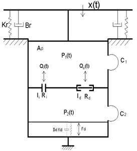
Fig. 2Structure model of an active control mount
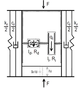
Fig. 2 shows thestructure model of the ACM, which is an amalgamation of the structure of the hydraulic mount and an actuator system. But the role of the decoupler is changed to a piston because of the actuator, so that it transmits the force from the actuator to the engine and chassis through the upper chamber. The role of the inertia track is also changed: in hydraulic engine mounts, the inertia track generates frequency dependent stiffness and damping. However, in the active control engine mount, it just relieves the static pressure in the upper chamber.
Because passive hydraulic mount has superior isolation ability in the low frequency range, and active actuator can provide highly efficient vibration control performance in relative high frequency range, so the active engine mount can isolate the vibration of engine in much wider frequency range. At the same time, the numerical simulation shows that the active control engine mount is capable of significantly reducing the vibration transmission.
2. Analytical modeling
The modeling of the active engine system is restricted to three degrees of freedom. However, note that the assumptions are made for this system [3].
1) The displacement is small compared to system dimensions.
2) The spring force is linear around the working point.
3) The upper plate (engine body) on the vibration isolation system is a rigid body.
4) Fluid is incompressible, and fluid density in chambers and fluid track is the same.
5) Mass of rubber spring, upper and lowerconnectors are negligible.
6) Damping of both lower diaphragm and decoupler membrane are negligible.
7) Leakage path tending to short-circuit fluid track is ignored.
These assumptions are used to model the vibration system in this work and Fig. 3 shows the coordinate system [3].
Fig. 3Coordinate system [3]
![Coordinate system [3]](https://static-01.extrica.com/articles/14908/14908-img3.jpg)
The state space format for the equations of motion of vibration system is:
where matrix A, B, C and D are defined as:
where ka is the actuator spring constant, Da is the damping parameter.
3. Validation of the mathematical model
In order to validate this newly analytical model in this work, in this section, the analytical model is validated using a finite element model set up in ANSYS which is a widely accepted commercial FEM software [4]. A finite element analysis (FEA) method is conducted in ANSYS and compared with analytical model for validation.
Table 1 shows the modal frequency of the vibration system from both the finite element model in Fig. 4 and the mathematical model by state space method.
Table 1Validation of the mathematical model by comparing to the finite element model in MATLAB and ANSYS
Modes | Frequency (Hz) Finite element model | Frequency (Hz) Mathematical model | Difference (%) |
The first modal | 6.84 | 6.84 | 0 |
The second modal | 11.69 | 11.84 | 1.3 |
The third modal | 11.73 | 12.76 | 8.0 |
It can be seen that both modal frequency are very close to each other, so that it can said the model implemented in this work is reliable [5]. With the validated active mounting system model, it is possible to conduct the control strategy modeling and the design optimization using GA.
Fig. 4The finite element model
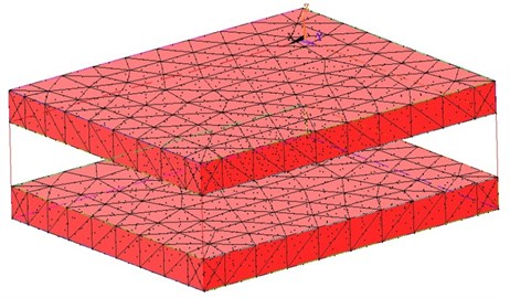
Table 2Model parameters
Parameter | Value |
Da damping | 20 Ns/m |
ka stiffness | 8902 N/m |
m upper mass | 19.274 kg |
L1 | 0.348 m |
L2 | 0.3 m |
a | 0 m |
Jxx inertia of x-axis | 0.1446 Kg/m4s |
Jyy inertia of y-axis | 0.1676 Kg/m4s |
4. Control strategy
In this section, the control strategy will be analyzed by using the linear quadratic regulator (LQR) method, which is a well-known design technique that provides practical feedback gains [6]. The LQR controller in Simulink/MATLAB for this feedback active vibration control is shown in Fig. 5, where step is disturbance input, u is the control vector. By implementation of the LQR controller, we find that the vibration isolation takes place attenuating the disturbance coming form engine.
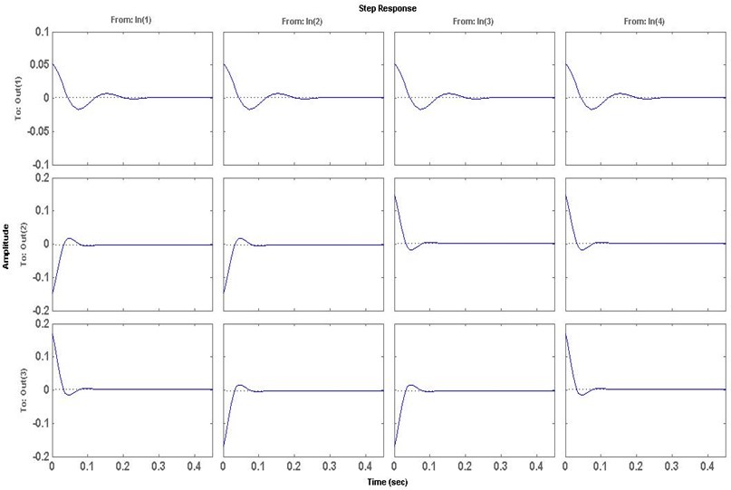
Transmitted acceleration with and without control are presented in Fig. 6 and Fig. 7 in time domain.
Figs. 6 and 7 show the response of system under the disturbance in time domain. It can be seen form Fig. 6 and Fig. 7 that the active engine mounting vibration system takes place right from the very beginning when subjected to step disturbance signal input. As input of the step disturbance activates, the transmitted acceleration has been increase to a greater range. This increase in the transmitted acceleration at engine mount decreases passenger comfort and smooth ride, working condition such as a vehicle through a rough road in a very short time.
The second line and the third line in Fig. 6 and Fig. 7 show that the response of the longitudinal acceleration is much faster and the lateral acceleration weakens a lot with LQR controller. It can be noticed that at the time interval of 0-0.5 sec, transmitted accelerationat active engine is reduced from 0.05 to 0.01 m/s2 (approximately). The first line in Fig. 6 and Fig. 7 shows that the attenuation of the vertical acceleration is more outstanding for LQR controller. It can be seen that at time interval of 0-0.3 sec, the transmitted acceleration has been attenuated to a value of 0.02 m/s2. The magnitude of the transmitted acceleration using LQR controller is reduced from 0.04 to 0.02 m/s2 from time interval 0.3 sec. At the same time, the LQR controller can also weaken the heel and pitching direction of rotation.
Fig. 5Implementation of LQR controller in Simulink/MATLAB
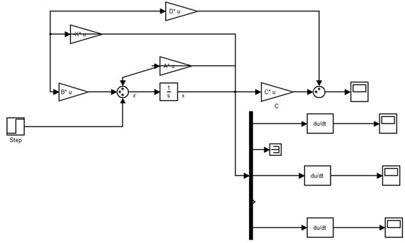
Fig. 6Control response without LQR controller
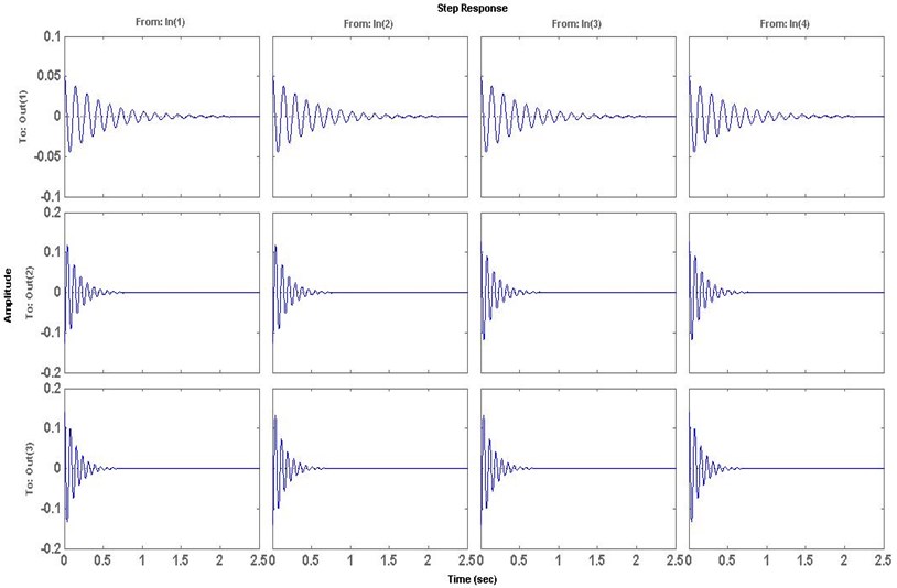
By comparing the simulation results, it is quite clear that LQR controller is effective in restricting the transmitted force to the chassis. It is observed that the vibration attenuation is obtained for a period less than 0.3 second. The result confirmed that the model with LQR control algorithm is able to reduce significantly the vibration transmission.
By implementing LQR controller in Fig. 7, the value of gain K is calculated by adjusting the Q and R weights matrix. By doing various iterations the values for R and Q are set, so that optimal results are obtained. There are various methods of selecting values of the weights which will lead to the optimal control of an associated system. These methods are cheap control, expensive control and terminal control. In this paper, each of the methods was used to obtain our weights and the one leading to optimal control of our system was chosen.
Fig. 7Control response with LQR controller
5. Optimization via GA
Fig. 8Fitness function value in GADST
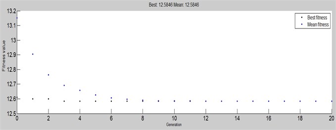
The selection of weight matrices in LQR is very importance and it straight affects the control performance. But the weight matrices are usually set by experience of designer and so the optimal control performance could not be obtained. The genetic algorithm (GA) is an optimization and search technique based on evolution, and it has been applied to many optimization problems [7, 8]. This work examines the application of genetic algorithms in optimizing the weight matrices of linear quadratic regulator [9]. The objective function for GA is:
where EA is the engine body vertical acceleration, PA is the pitching acceleration, RA is the roll acceleration, pas is the passive acceleration. The result of the GA objective function in MATLAB/GADST GA toolbox is shown in Fig. 8.
6. Conclusions
In this paper, the vibration control performance of a selected active control engine mount system with LQR controller is evaluated. Then, an analytical model which includes the hydraulic engine mount and active control technique are implemented and analyzed [10]. This newly proposed model is validated by compared with FEA. In addition, the LQR controller is integrated into the model in order to achieve better vibration reduction as shown in numerical examples. Also, the application of GA for optimization design of LQR weight matrices is studied as well to have the optimal configuration of control strategy. For future work, different control techniques can be examined for the disturbance rejection such as LQG and robust control methods, which probably could provide more effective ways of dealing with disturbance reduction.
References
-
YunheYu, Nagi G. Naganathan, Rao V. A literature review of automotive vehicle engine mounting systems. Mechanism and Machine Theory, Vol. 36, Issue 1, 2001, p. 123-142.
-
Geisberger A., Khajepour A., Golnaraghi F. Non-linear modeling of hydraulic mount: theory and experiment. Journal of Sound and Vibration, Vol. 249, 2002, p. 371-397.
-
Thorsten Muller, StefanHurlebaus, Uwe Stobener Modelling and control techniques of an active vibration isolation system. Conference and Exposition on Structural Dynamics, 2005.
-
Xie Zhengchao, Shepard W., Steve Jr. Development of a new finite element and parametric study for plates with compressible constrained layer damping. Journal of Composite Materials, Vol. 46, Issue 11, p. 1263-1273.
-
Xie Zhengchao, Wong Pak Kin, Huang Xinzheng, Wong Hang Cheong Design of an active vehicle suspension based on an enhanced PID control with wheelbase preview and tuning using genetic algorithm. Journal of the Chinese Society of Mechanical Engineers, Vol. 33, Issue 2, 2012, p. 103-112.
-
Yuan Yun, Yangmin Li Active vibration control based on a 3-DOF dual compliant parallel robot using LQR algorithm. International Conference on Intelligent Robots and Systems, 2009, p. 775-780.
-
Xie Zhengchao, Wong Pak Kin, Ian IanChong A genetic algorithm-based optimization design on self-sensing active constrained layer damped rotating plates. Journal of Intelligent Material Systems and Structures, Vol. 22, Issue 17, 2011, p. 2069-2078.
-
Xie Zhengchao, Wong Pak Kin, Chong Ian Ian Modeling and analysis of rotating plates by using self-sensing active constrained layer damping. Journal of Mechanical Science and Technology, Vol. 26, Issue 10, p. 3009-3016.
-
Xie Zhengchao, Wong Pak Kin, Zhang Long Numerical modeling and control of rotating plate with coupled self-sensing and frequency-dependent active constrained layer damping. Mathematical Problems in Engineering, 2012.
-
Xie Zhengchao, Lou Inchio, Ung Wai Kin Freshwater algal bloom prediction by support vector machine in Macau storage reservoirs. Mathematical Problems in Engineering, 2012.
About this article
This project is supported by MYRG155(Y2-L2)-FST11-XZC which is funded by Research Committee of University of Macau.
