Abstract
This paper investigates the vibration and optimal design of a rotating constrained layer damped plate system. Most of the existing researches treat the plate structures as beams. This work, however, models rotating structures as plates. At the same time, the existing research shows that the constrained layer damping (CLD) is an effective technique for vibration suppressions. Through the models investigated, this paper develops a single layer plate finite element model for a constrained layer damped rotating plate to improve both the accuracy and versatility over previous beam CLD models. Due to the multiple design variables and complex responses, a genetic algorithm (GA) is applied to determine the thicknesses of the viscoelastic damping layer and the constraining layer so that the amplitudes with first two modes of the driving point mobility at a selected point of the rotating plate can be minimized. Numerical results show that GA works effectively with developed single layer plate finite element model to find out the optimum configuration.
1. Introduction
Constrained layer damping (CLD) is an effective approach for vibration suppressions. The fundamental mechanism of CLD is that the relative motion of two face layers leads to the deformation of the damping layer; the energy consumed through the deformation of the damping layer results in the damping effects. Relatively large damping ratios can be achieved through a wide range of available viscoelastic materials.
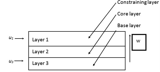
In literature, investigations have been conducted on constrained layer damping for beam structures. These researches widely employed an assumption proposed by Ross, Ungar and Kerwin (RKU) [1], suggesting that there is only shear deformation (pure shear) in the damping layer. In this assumption, the two face layers are treated as Euler-Beams while the core layer only experiences shear deformation. The motions associated with this assumption are illustrated in Fig. 1. For the convenience of the discussion, two face layers are called the constraining layer and the base layer respectively in this paper, while the middle layer is called the core layer. The layers are also denoted by numbers 1, 2 and 3, respectively, throughout this work. The displacements and are employed to represent the longitudinal displacements of face layers 1 and 3 respectively. is utilized to denote the transverse displacement of sandwich structure, which is identical for each of the three layers. Shear deformation in the core layer is determined from the relative motion between and.
While the assumptions described above are widely used, they are not always valid in certain structures. Rao [2] studied the problem using the same transverse displacement assumption as that in [1] but with additional assumptions that the longitudinal displacement varies linearly across the thickness of each layer, and the displacement is continuous across the layer connections. In that work, all of three layers are treated as Timoshenko beams instead of Euler beams used in the RKU model. Zapfe and Lesieutre [3] presented a beam finite element that can be regarded as the finite element implementation of the Rao’s model. Based on the work of [3], Xie and Shepard [4] developed a new plate finite element to consider the compression effect of CLD structures.
Fig. 1RKU model displacements for a CLD sandwich beam
Recently the constrained layer damping is employed for the vibration suppressions of rotating structures, which has wide applications in industries such as wind turbines, helicopters, and vessels. Rotating beams, a simplification of rotating plates, have been extensively investigated, including fundamental dynamics [5] and constrained layer damping studies [6-7]. Fung et al. [8] studied active constrained layer damping (ACLD) application on rotating beam. Yoo et al. [9-11] studied the dynamics of rotating bare plates using analytical approach. Based on the work in [8], Liu et al. [12] developed a plate finite element model for a rotating bare plate. Liu et al. [13] extended their own work in [12] to the active control of rotating bare plates through the finite element approach. It is worth noting that all of the work mentioned above utilized the same assumptions as those in RKU model that there is only shear strain in the core layer, whereas the constraining and base layers experience only longitudinal extension strain.
Since it is often desired to obtain the best performance for a particular application, design optimization can often be a significant issue. Many optimization methods are available, such as calculus-based methods like the conjugate gradient method and differential correction. In some cases, the model associated with optimization issue is complicated or even unknown; it is difficult for these methods to handle such optimization issues. Genetic algorithm (GA) could be a good choice because GA is an optimization method based on stochastic search, requiring only the knowledge of the objective function and not any of its derivatives. GA uses natural evolutionary principles to obtain offspring with characteristics better than those of the parents. The optimization results are typically at or close to the global optimum. Some GA optimization methods have been applied to the constrained-layer damped structures. Hau et al. [14] constructed a FEM model which contains the frequency-dependent viscoelastic material for a rotating beam. This model was then combined with GA to obtain an optimum configuration.
In this research, a plate finite element model is originally developed to extend the previous research from the beam to the plate and is employed to model the multi-layer rotating plates. A GA approach is then used with the model to find the optimal thickness for both the damping layer and the constraining layer for vibration suppressions. A comparison is provided in the numerical examples, demonstrating that the optimum solutions obtained from GA can obtain the best vibration suppression effects while minimizing the utilization of the damping material. The proposed plate finite element model is applicable for multi-layer (more than three) rotating plates, and the design approach can be extended to optimize more complex damped rotating structures such as wind turbines in the future.
2. Finite element modeling and validation
2.1. Assumptions and kinematics relations
Prior to introducing the rotating plate finite element model, the assumptions as those in [2] should be introduced. Note that the assumptions in [2] are for beams.
1) The transverse displacements of all three layers are equal.
2) The longitudinal displacement is linearly distributed across the thickness of each layer.
3) There is no slip between the layers.
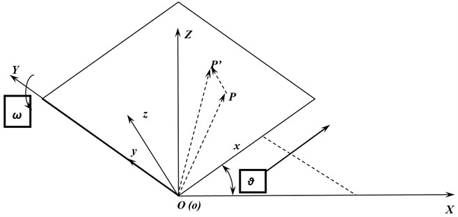
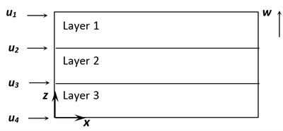
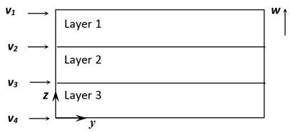
These assumptions are used in this work to model the rotating plate. Fig. 2 shows the proposed displacement field for the rotating plate with angular velocity . and are the longitudinal displacements at the contacting interfaces of different layers, and the longitudinal displacement of each layer varies linearly between the top and the bottom surfaces as shown in Fig. 2. is the transverse displacement for all of the three layers.
Fig. 2Proposed displacement field
a)
b)
c)
Note that there are two coordinate systems in Fig. 2, i.e., a rotating coordinate system attached to the rotating plate, and a global coordinate system that is fixed without rotation. The plate rotates with the rotating coordinate system around the axis of the fixed coordinate system The transformation matrix between two coordinate systems is defined as [10]:
where is the angle between the axis and axis. Taking an arbitrary point on the rotating plate which moves from to after the deformation, the:
The term: , is the so-called ‘stiffening effect’ [11], which are the coupling terms between the transverse displacement and the longitudinal displacement due to the centrifugal force of the rotation. The , , and are the linear displacement of point in the rotating coordinate system . The transformation of the displacement from the z coordinate system to the coordinate system can be made as follows:
With the proposed displacement field, the kinetic and strain energy can be obtained respectively. The equations of motion can then be derived accordingly, and they are presented in the following sections.
2.2. Strain and kinetic energies
Given the displacement field, the strain energy of the th layer in the rotating plate can be represented as:
where is the thickness of the th layer, and are the Young’s and shear modulus of the th layer respectively.
The kinetic energy is dependent on structure’s motion. Taking the time derivative of displacement in Eq. (2) gives:
The kinetic energy of the th layer then can be calculated as:
where is the angular velocity of the plate, and is the material density of the th layer.
2.3. Finite element discretization
Once the kinetic and strain energy are obtained, the displacement field can be discretized using the new plate finite element. Fig. 3 shows the th layer of the proposed new plate finite element. It is worth noting that the middle nodes are employed to avoid shear locking [3]. As a consequence, there are 25 degrees of freedom for the th layer as shown in Fig. 3 and 41 degrees of freedom for all of three layers.
Fig. 3Proposed new plate finite element
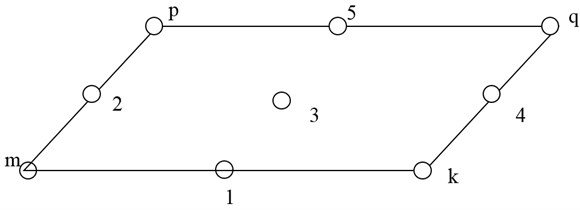
a)
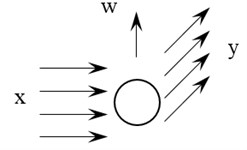
b) For nodes p, q, m, k
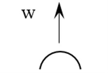
c) For all other nodes
The displacement vector of the th layer with this new plate finite element becomes as follows:
For the th layer of plate finite element, the proposed displacement field (Fig. 3) can be organized as:
and the dimensions of matrix and are and , respectively. Both matrixes are given as follows:
where and are respectively the transverse coordinate and the thickness of the th layer. And:
where are the shape functions for the longitudinal displacement and are the shape functions for the transverse displacement. Since they can be calculated according to many finite element textbooks, they are not given in detail in this work.
Also, the displacement vector can be assembled to the global displacement vector of the whole plate finite element with three layers:
where is a mapping matrix of the th layer, and is the total number of degrees of freedom in the plate finite element (41 for three layers).
Substituting Eq. 7 into Eqs. (2), (3) and (5), and neglecting high order terms, the kinetic and strain energy of the th layer can be reorganized as:
where and are the th row of the matrix and , respectively.
2.4. Equations of motion
With Eqs. (11), (12) and (17), the global equations of motion for the rotating plate can be obtained using Lagrange formula as follows:
where:
and are mass and stiffness matrix of the rotating plate, respectively. and are the elastic strain stiffness in coordinate system and stiffening matrix, respectively. is the global displacement vector of the rotating plate. and represent velocity and acceleration vectors, respectively. Since the same coupling terms between the transverse and longitudinal displacements are used, the derivation of RP in this work is similar to that in [12]. It is worth noting that the proposed displacement field and derivation approach in the present study are different from those in [12], where the bare rotating plate is investigated in the latter while the three layer CLD structure is considered in this study. Here the Lagrange formula is applied to each layer () first, and then the local equation of motion of each layer is assembled to form the global Eq. (13).
2.5. Validation of the finite element model
In this section, the developed finite element model is validated using data from the open literature. We consider a rotating and constrained layer damped sandwich beam as in [8] with the length of 0.3 m, and detailed configurations can be found in [8]. The first three bending modes of this beam are calculated using the newly developed finite element model and compared with those in [8], where the rotation speed is set at 30 revolutions per-minute (rpm). One can see from Table 1 that all of the first three modes obtained from the new finite element model match pretty well with those in [8]. It is interesting to note from Table 1 that the developed new finite element model is able to identify the first torsion mode while the beam model in [8] is not, and this is an advantage of plate model over the beam model. With the validated constrained layer damped plate model, it is possible to perform the optimization for the constrained layer damping plate.
Table 1Comparison between results of new plate finite element model and [7] with 30 rpm rotation speed
Modes | Frequency (Hz) | Difference (%) | Damping ratio (%) | Difference (%) | ||
New FE model | Reference [7] | New FE model | Reference [7] | |||
The first bending | 20.2 | 20.2 | 0 | 3.8 | 3.8 | 0 |
The second bending | 106.1 | 104.0 | 2.0 | 2.3 | 2.3 | 0 |
The first torsion | 186.3 | N/A | N/A | 0.49 | N/A | N/A |
The third bending | 290.1 | 277.0 | 4.5 | 1.15 | 1.23 | 7.0 |
3. Optimization via genetic algorithm (GA)
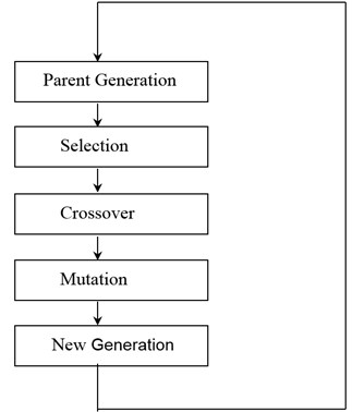
GA is not new to the field of mechanical designs. In 1975, Holland published the book of ‘Adaptation in Natural and Artificial System’ [15] and systematically described the topic of GA as applied to biological research. Since then, GA has been widely used in many fields such as structure optimizations. In general, GA uses stochastic search and natural evolutionary principles as the basis for optimizations. The algorithms first create a population of “individuals”, typically the binary strings coded to represent the parameters of the problem. The best elements of the population are then selected for various operations as shown in Fig. 4, and details on each operation can be found in [16]. The goal of each step in the algorithm is to obtain a new generation, referred to as offspring, which is closer to the optimal solution than the parent generation.
In this work, the thickness of the damping layer and the thickness of the constraining layer are treated as the design variables encoded into a binary string using a multi-parameter, mapped, fixed-point coding [16]. Each of the thicknesses is coded using 20 bits, so the total length of the string needed to describe the configuration of the sandwich beam is 40 bits. The population of each generation is composed of a specified number of such strings. The corresponding dynamic response of the rotating plate, associated with each string is used to calculate the fitness of the string. The fitness is used to ultimately determine the survivability of the particular string in the evolution. In this research, the fitness is defined as the summation of reciprocals of maximum amplitudes of the structural response at its first two resonant frequencies.
Fig. 4Procedure for genetic algorithm
The FEM code reads the strings generated from the GA code and calculates the dynamic response for each configuration. The dynamic response is then used in the embedded objective function in order to calculate the fitness for that particular solution. The particular objective functions considered for the optimization used herein are discussed below.
4. Numerical example
In order to examine the capabilities of the code, one can consider a constrained layer damped rotating plate with parameters as given in Table 2. For the GA parameters, the population size is 40 with single point crossover. Furthermore, forty bits are allocated for strings which represent the two design variables with twenty bits for each. The mutation rate is set as the reciprocal of the string length, which is 0.025. For this study, the first two mode amplitudes of driving point mobility at one selected point of the rotating plate will be minimized. The location of the selected point is at the point with one half of the plate length away from the free end and two third of the plate width away from the front side edge. Consequently, the response is presented in the frequency domain. While the driving point mobility amplitudes are minimized here, the method is flexible to handle other objective function.
Table 2Parameters for the case study of optimization
Parameters | Value | Parameters | Value |
Thickness 1 | Variable | Shear modulus 1 | 24.96 Gpa |
Thickness 2 | Variable | Shear modulus 2 | 0.2615 Mpa |
Thickness 3 | 0.005 m | Shear modulus 3 | 27.3 Gpa |
Young’s modulus 1 | 64.9 GPa | Density 1 | 7600 kg/m3 |
Young’s modulus 2 | 29.8 MPa | Density 2 | 1250 kg/m3 |
Young’s modulus 3 | 71 GPa | Density 3 | 2700 kg/m3 |
Width | 1 m | Length | 1.5 m |
Rotation speed | 300 rpm | ||
Loss factor | 0.38 | ||
1 – Constraining layer, 2 – Damping layer, 3 – Base material | |||
Depending on the goals of the design, one can specify different objective functions for use in the GA optimization. Nakra [17] tried to maximize the system loss factor for certain modes. Zheng et al. [18] set the minimization of the vibration energy as the objective. Xie et al. [19] adopted GA to reduce the vibration amplitude of first two bending modes of composite beams. Since the response at the resonant frequencies is typically the most harmful, the initial objective function used here involves minimizing the driving point mobility amplitudes that would result from the simultaneous excitation of the first two modes (the first bending and the first torsion mode) at their respective resonance frequencies. For this case, the fitness (FS) is defined as so that and can be minimized when the GA finds the configuration of the maximum fitness. Here, and are the first two mode amplitudes of the driving point mobility, respectively, at the selected point on the plate. As noted earlier, there are two design variables: 1) the thickness of damping layer and 2) the thickness of constraining layer . In order to make the optimization practical, it is also necessary to specify the limits on the thickness of the two layers. For this problem, the thickness for these two layers must be kept within a predefined practical range, which can be expressed as:
where the maximum and minimum values of both layers are 0.0012 m and 0.0002 m, respectively. The decoded values of the binary strings are mapped into the range between the upper and lower limits automatically.
By using the above objective function and the layer thickness limits, the GA algorithm can find the optimal thicknesses for the two layers. In this case study, where the first two modes are considered simultaneously, and viewed as the criteria of the optimum configuration.
With the above settings, the GA and the FEM work together effectively such that the population appears to converge after the evolution of about sixteen generations, as shown in Fig. 5. The optimization takes about 72 hours (three days roughly) running on a 2.67 GHz PC, and most of the time is spent for the calculation of structure stiffness matrix which contains many differential operations. If a larger population size and more generations are used, the convergence of optimization process will take longer time.
Fig. 6 shows the responses of several different configurations. In the optimum configuration, the resulting thicknesses for the layers are 0.0012 m, 0.00085 m and 0.005 m for the base layer, the damping layer and the constraining layer, respectively. The responses of a bare rotating plate with a thickness of 0.005 m are used for the comparison purposes. The responses for the two configurations that respectively have the maximum and minimum layer thicknesses (i.e. , and , ) are also employed for more comparison. Fig. 6 shows that the optimum configuration performs about as well as the maximum thickness configuration and the responses for these two configurations are clearly much lower than the configuration without damping.
The reason that this work selects upper and lower end values of the thickness range is that engineers could benefit from this optimization by having maximum vibration reduction with the minimum material cost. It is not necessarily that more damping material can lead to better performance. As indicted previously, because of the complex modulus of viscoelastic material, the damping which to lower the vibration amplitude depends on the deformation of the damping layer. The more deformation in the damping layer, the more damping can be “squeezed” out of it. And this is the fundamental principle for the constrained layer damped structures. So, based on this consideration, following comparisons will made in order to illustrate the performance of proposed approach including CLD modeling, application, and optimization.
Fig. 5Evolution of the best-so-far fitness vs. generation, during the optimization process
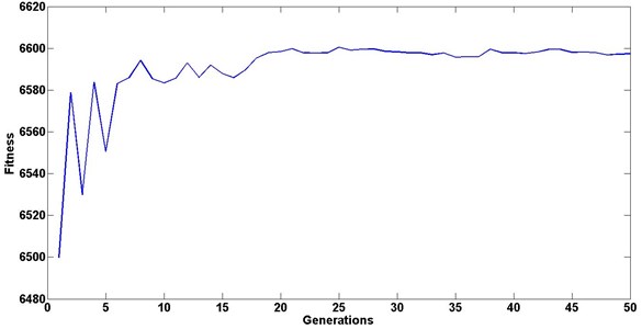
Fig. 6Comparison on frequency response function (FRF) of different configurations: solid line – optimum configuration; dashed line – maximum thickness configuration; dash dot line – minimum thickness configuration; dotted line – bare rotating plate
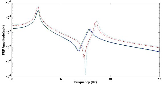
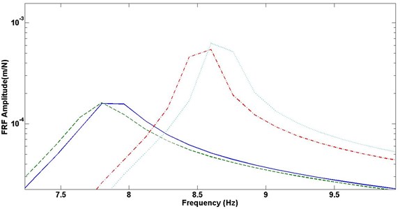
Fig. 7 and 8 show detailed comparisons at the first and the second mode, respectively. It can be seen that the optimum configuration has about the same response level as the configurations with the maximum thickness at both resonant frequencies, while the damping layer thickness in the optimum configuration is lower than the configuration with the maximum thickness, indicating that less material can achieve about the same performance. Actually, the fitness values are 6597 for the optimum configuration, and 6471 for the maximum thickness configuration. Also, both configurations have a much lower response level than the minimum thickness configuration and the bare rotating plate at both resonant frequencies.
From the above comparisons, it can be seen that the first mode of the damped beam has a higher response than the response for the second mode. Since it is common to excite the first resonant frequency, the optimization of the first mode is more important and may be more important than the alternative selection of the optimum configuration over multiple resonant frequencies. Nevertheless, like some existing works [19], the selection of the best optimum approach must be based on some knowledge of the excitation and the critical response characteristics.
Fig. 7Comparison on frequency response function (FRF) at the first resonant frequency: solid line –optimum configuration; dashed line – maximum thickness configuration; dash dot line – minimum thickness configuration; dotted line – bare rotating plate
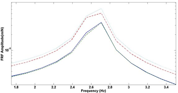
Fig. 8Comparison on frequency response function (FRF) at the second resonant frequency: solid line – optimum configuration; dashed line – maximum thickness configuration; dash dot line – minimum thickness configuration; dotted line – bare rotating plate
5. Conclusion
This research is the first attempt at using a plate finite element method to model the rotating plates with three layers. The proposed displacement field and degrees of freedom enable this finite element model to capture the shear and extension deformation in all three layers. This model is validated using the results of natural frequencies and damping ratios from the published literature. In order to find the geometric configurations to achieve the best desired structural response, the GA method is originally used to minimize the driving point mobility amplitudes of the constrained layer damped rotating plate in a frequency range that includes the first bending and the first torsion modes. The optimization result shows that GA can effectively work with the developed single layer plate finite element for rotating CLD plate to yield a satisfactory and very close vibration reduction to the configurations with a thicker layer of damping materials.
References
-
D. Ross, E. E. Ungar, E. M. Kerwin Damping of plate flexural vibrations by means of viscoelastic laminae. ASME Annual Meeting Structural Damping, New York, 1959, p. 49-88.
-
D. K. Rao Vibration of short sandwich beams. Journal of Sound and Vibration, Vol. 52, 1977, p. 253-263.
-
J. A. Zapfe, G. A. Lesieutre Vibration analysis of laminated beams using an iterative smeared laminate model. Journal of Sound and Vibration, Vol. 199, Issue 2, p. 155-167.
-
Z. Xie, S. Shepard Development of a new finite element and parametric study for plates with compressible constrained layer damping. Journal of Composite Materials, Vol. 46, 2012, p. 1263-1273.
-
Y. A. Kulief Vibration frequencies of a rotating tapered beam with end mass. Journal of Sound and Vibration, Vol. 134, 1989, p. 87-97.
-
Guo-Ping Cai, Jia-Zhen Hong, Simon X. Yang Modal study and active control of a rotating flexible cantilever beam. International Journal of Mechanical Science, Vol. 46, 2004, p. 871-889.
-
J. B. Yang, L. J. Jiang, D. Ch. Chen Dynamic modeling and control of a rotating Euler-Bernoulli beam. Journal of Sound and Vibration, Vol. 274, 2004, p. 863-875.
-
E. H. K. Fung, D. T. W. Yau Vibration of a rotating flexible arm with ACLD treatment. Journal of Sound and Vibration, Vol. 269, 2004, p. 165-182.
-
H. H. Yoo, C. Pieere Modal characteristic of a rotating rectangular cantilever plate. Journal of Sound and Vibration, Vol. 259, 2003, p. 81-96.
-
H. H. Yoo, S. K. Kim Free vibration analysis of rotating cantilever plates. AIAA Journal, Vol. 40, 2002, p. 2188-2196.
-
H. H. Yoo, S. K. Kim, D. J. Inman Modal analysis of rotating composite cantilever plates. Journal of Sound and Vibration, Vol. 258, 2002, p. 233-246.
-
J. Liu, J. Hong Geometric nonlinear formulation and discretization method for a rectangular plate undergoing large overall motions. Mechanics Research Communications, Vol. 32, 2005, p. 561-571.
-
L. Liu, Z. Zhang, H. Hua Dynamic characteristics of rotating cantilever plates with active constrained layer damping treatments. Smart Materials and Structures, Vol. 16, 2007, p. 1849-1856.
-
L. C. Hau, E. H. K. Fung, D. T. W. Yau Multi-objective optimization of an active constrained layer damping treatment for vibration control of a rotating flexible arm. Smart Materials and Structures, Vol. 15, 2006, p. 1758-1766.
-
J. H.Holland Adaptation in natural and artificial system. The University of Michigan Press, 1975.
-
D. E.Goldberg Genetic algorithms in search, optimization, and machine learning. Addison-Wesley Press, 1999.
-
B. C.Nakra Vibration control in machines and structures using viscoelastic damping. Journal of Sound and Vibration, Vol. 211, 1998, p. 449-465.
-
H. Zheng, C. Cai Optimization of partially constrained layer damping treatment for vibrational energy minimization of vibrating beams. Computers & Structures, Vol. 82, 2004, p. 2493-2507.
-
Z. Xie, S. Shepard, K. Woodbury Design optimization for vibration reduction of viscoelastic damped structures using genetic algorithms. Shock and Vibration, Vol. 16, 2009, p. 455-466.
