Abstract
The paper presents the geometric models of flexsplines and wave generators developed based on the actual construction and geometric dimensions of manufactured harmonic drives (type CSD, CSG, HFUS and HFUC). In order to enhance the data preparation process, the model geometry was recorded in a parametrical form. By altering the individual properties of the models, it is possible to automatically generate finite element grids for flexsplines and wave generators of various geometrical and structural properties. The calculations prepared for the sake of the study by application of the finite element method (FEM) were conducted using the Femap/NX Nastran software. A preliminary numerical modal analysis of the structural solutions for the harmonic driver flexsplines and wave generators assumed to be applied was conducted.
1. Introduction
Recent technical developments have caused the emergence of new and improvement of old torque transformation methods. For large ratios, the classical multi gear transmissions are being replaced by planetary gears, and those by a more efficient harmonic drives [1-3]. Gear, which was first to use elastic deformation of the toothed ring gear in order to transform the torque, was patented in 1959 by W. Musser. Since then, especially during the last twenty years, various types of harmonic drive were developed and patented. Compared to classical toothed gears, harmonic drives have numerous advantages, but there are some disadvantages as well. Their main advantages include: high torque capacity, excellent positioning accuracy and repeatability, compact design, zero backlash, high single stage reduction ratios and high torsional stiffness. On the other hand, their drawbacks are: high elasticity and nonlinear stiffness and damping. The application of toothed harmonic drives in various fields of life is more and more wide. They are currently used by the automotive and space industry, in aviation, medicine, automatics and robotics, while most of them are two-wave harmonic drives with mechanical wave generators. When considering transmissions used in automatic control systems, issues connected with their high kinematic precision, smoothness of torque transmission and dynamic characteristics (stiffness, damping, moments of inertia and natural frequencies) gain utmost importance.
A harmonic drive (Fig. 1) consists of a toothed mechanism, which is composed of three main elements. The circular spline (mark 1 in Fig. 1) is a solid steel ring with internal teeth. The flexspline (mark 2 in Fig. 1) is a flexible steel cylinder with external teeth. The drive is executed by the wave generator (mark 3 in Fig. 1), a thin-race ball bearing that is fitted onto an elliptical plug. Generator produces the elastic deformation waves of the flexspline. Depending on the number of waves distortion we distinguish one-wave and two wave harmonic drives. The flexspline is the main component of a harmonic drive, which can generate a repeated vibration by the wave generator. From this reason, the flexspline should have flexibility and good vibration characteristics.
While choosing the flexspline material [3, 5-8], one must consider the deformations and stresses occurring in the flexspline operating in the driver, both unloaded and loaded by the torsional moment. The heat treatment method to be applied to a spline must be determined entailing the criterion of ensuring its elastic properties as well as the service life assumed.
Modal analysis is the study of the dynamic character of a system which is defined independently from the loads applied to the system and the response of the system [9-12]. Analytical models are developed to describe the system mass and stiffness characteristics of a component. The model is decomposed to express the part in terms of its modal characteristics (frequency, damping and shapes). The dynamic characteristics help better understand how the structure will behave and how to adjust or improve the component design. Using the finite element method and modal analysis in the analysis of flexspline by different authors can be found in the works [13-18].
On the basis of the actual construction and geometric dimensions of mass-produced harmonic drives (type CSD, CSG, HFUS and HFUC [4]) the geometric models were developed. Figure 2 shows the actual HFUC type gear and the CAD-developed geometric model.
Fig. 1The main components of a harmonic drive: 1 – circular spline, 2 – flexspline, 3 – wave generator [4]
![The main components of a harmonic drive: 1 – circular spline, 2 – flexspline, 3 – wave generator [4]](https://static-01.extrica.com/articles/14763/14763-img1.jpg)
Fig. 2Harmonic drive: a) type HDUC [4], b) geometric model
![Harmonic drive: a) type HDUC [4], b) geometric model](https://static-01.extrica.com/articles/14763/14763-img2.jpg)
a)
![Harmonic drive: a) type HDUC [4], b) geometric model](https://static-01.extrica.com/articles/14763/14763-img3.jpg)
b)
2. Numerical modal analysis of flexsplines
The flexspline [2, 3] in a harmonic drive has elastic properties and, depending on the generator, it may take on specific shapes. In a single-stage harmonic drive, the flexspline may be either a stationary or a moving part. In the first case, it is connected directly or through a toothed clutch to the gearbox housing, whereas in the second case, it is connected directly or through a clutch to an output shaft.
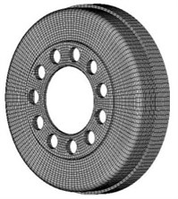
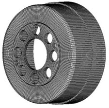
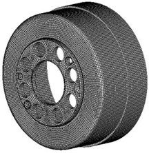
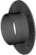
Nowadays, steel flexsplines in toothed harmonic drives are most often manufactured as [4]: short cup-type (Fig. 3a), cup-type (Fig. 3b and 3c) or with an outer flange (Fig. 3d).
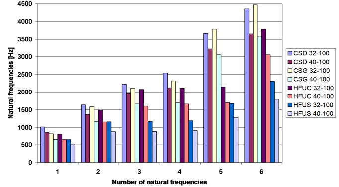
The study developed eight three-dimensional models that represent the four flexspline design solutions adopted for the analysis. For each design solution two models with different dimension sets were assumed. During the conducted calculations the forms of natural frequencies for the developed flexspline models were determined using the FEM. Sample three-dimensional numerical models of the flexsplines with the finite element mesh are shown in Figure 3. As a material flexspline adopted steel with the characteristics given in Table 1. Figure 4 summarizes the natural frequencies values for all of the analyzed flexspline design solutions. Table 2 shows vibration form examples for CSD, HFUC and HFUS type.
Table 1Properties of the steel 42CrMo4
Tensile modulus (GPa) | 210 |
Shear modulus (GPa) | 80 |
Poisson’s ratio | 0.3 |
Density (kg/m3) | 7850 |
Fig. 3The FEM models of flexsplines: a) short cup-type CSD, b) a cup-type CSG, c) a cup-type HFUC, d) with an outer flange HFUS
a)
b)
c)
d)
Fig. 4Chart summary of the analyzed flexsplines natural frequencies
3. Numerical modal analysis of wave generators
The wave generator [2, 3] in a harmonic drive is a structural element which serves to deform the toothed ring of the flexspline. The principal task of the generator is to ensure a required number of deformation waves of the flexspline. In terms of the number of generated waves, generators may be divided into: single, double and triple wave ones. The generator may be mechanical, hydraulic or electric. Most frequently, mechanical generators are used in harmonic drives. With regard to their design features, mechanical wave generators can be divided into roller, cam and disc types. The application of a specific generator type depends on the purpose of the drive and its utilization.
Table 2Analyzed flexspline vibration shape
Shape vibration | Flexspline CSD 32-100 | Flexspline HFUC 32-100 | Flexspline HFUS 32-100 |
1 | 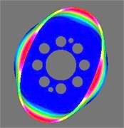 | 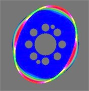 | 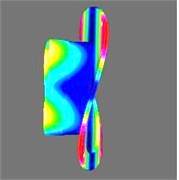 |
3 | 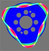 | 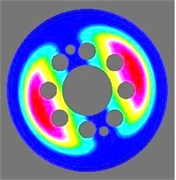 | 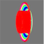 |
5 | 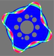 | 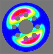 | 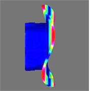 |
A cam generator [2, 3], unlike roller or disc generators, has an elastic bearing fixed onto the generator case, which generator most often is a cam of an elliptical profile. Generators of this type allow both the elastic bearing and a neutral layer the flexspline to be deformed to any form described by the shape of the generator cam.
Figure 5 presents a cam generator and its position against the toothed ring of the flexspline. The generator cam profile should guarantee obtaining a required form of deformation of the neutral layer of the flexspline. Elastic bearings used in cam generators have thinner outer and inner rings compared to typical bearings, which allows them to be deformed during the mounting of the bearing on the generator cam.
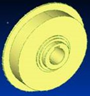
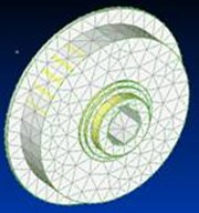
As part of the study, geometrical and numerical models were developed of cams of a mechanical wave generator used in drives of the CSD, CSG, HFUC and HFUS types [4]. Figure 6 shows an example of the analyzed generator cam for the HFUC drive. Generator cams used in drives of the CSD, CSG, HFUC and HFUS types have a shape of a disc (Fig. 6). The only differences between them result from a different width of the generator cam and additional thread relief. Generator cams of the CSG and HFUC drives have a larger width, with the same outer diameter, than the cams of drives CSD and HFUS.
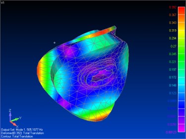
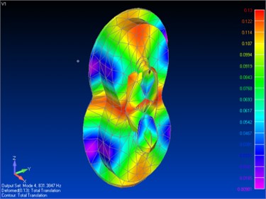
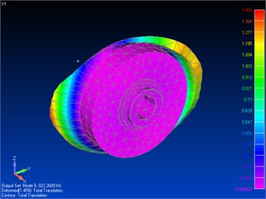
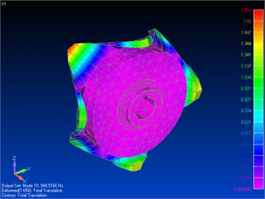
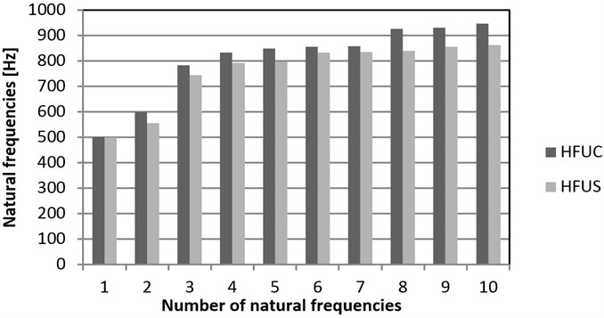
For the developed numerical models of wave generator cams of various harmonic drives, an analysis was carried out regarding the impact of two selected design features, the outer diameter and the cam width, on the form and values of natural frequency. Examples of the first, fourth, ninth and tenth form of vibration obtained for a HFUC drive, are shown in Figure 7. Examples of the calculation results are presented in Figures from 8 to 10. By analyzing the results obtained it can be confirmed that an increase of the outer diameter of a generator cam results in a reduction of the value of natural frequency (Fig. 8 and 9), whereas an increase of the cam width causes a slight increase of the natural frequency value (Fig. 10). The obtained forms of vibration for the analyzed cases were the same.
Fig. 5Cam generator: 1 – elastic bearing, 2 – wave generator cam, 3 – washer
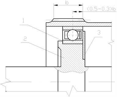
Fig. 6Cam generator: a) geometrical model, b) numerical model
a)
b)
Fig. 7Forms of vibration of the wave generator cam: a) first, b) fourth, c) ninth, d) tenth
a)
b)
c)
d)
Fig. 8The influence of the outer diameter of a generator cam on the natural frequency (HFUC)
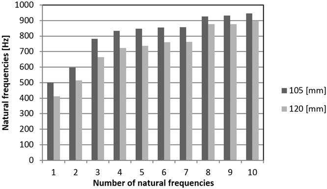
Fig. 9The influence of the outer diameter of a generator cam on the natural frequency (HFUS)
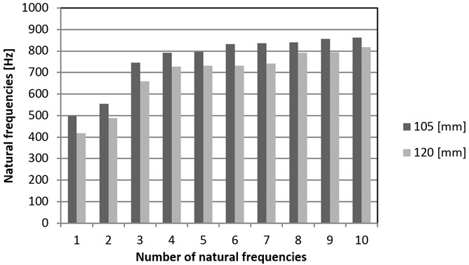
Fig. 10The influence of the generator cam width on the values of natural frequency for the outer diameter of a cam of 105 mm
4. Conclusions
The calculations performed using the FEM determined characters and natural frequencies for the developed flexspline models. Analyzed the CSD CSG, HFUC and HFUS flexsplines with varying features. The influence of the flexspline size on the results is important. Increasing the geometric dimensions for the same circular shape flexspline leads to a reduction in the vibration frequency (Fig. 4). The natural frequencies values are affected by the adopted flexspline design solution. The highest frequency values are observed for the CSD flexspline, and the lowest for the HFUS flexspline. Also, an analysis was conducted regarding the influence of selected structural features of wave generator cams on the forms and values of natural frequency. By analyzing the results of numerical calculations, it can be confirmed that an increase of the outer diameter of a generator cam results in a reduction of the value of natural frequency (Fig. 8 and 9), while an increase of the cam width causes a slight increase of the natural frequency value (Fig. 10).
References
-
Ivanov M. N. Harmonic gear drive. Moscow, 1981, (in Russian).
-
Ostapski W. Harmonic drive. Warsaw University of Technology Publishing House, 2011, (in Polish).
-
Mijał M. Synthesis of toothed harmonic drive. Rzeszow University of Technology Publishing House, 1999, (in Polish).
-
Harmonic Drive AG. General Catalogue, Germany, 2009.
-
Węgrzyn T., Piwnik J. Low alloy welding with micro-jet cooling. Archives of Metallurgy and Materials, Vol. 57, Issue 2, 2012, p. 539-543.
-
Łabaj J., Siwiec G., Oleksiak B. Surface tension of expanded slag from steel manufacturing in electrical furnace. Metalurgija, Vol. 50, 2011, p. 209-211.
-
Blacha L. Examinations of antimon displacement speed from blister copper in the process of vacuum refining. Archives of Metallurgy and Materials, Vol. 50, 2005, p. 989-1002.
-
Folęga P., Siwiec G. Numerical analysis of selected materials for flexsplines. Archives of Metallurgy and Materials, Vol. 57, 2012, p. 185-191.
-
Abhijit G., Xiaoping Z. Damage quantification using modal parameters. Journal of Vibroengineering, Vol. 9, Issue 2, 2007, p. 1-6.
-
Jamroziak K., Kosobudzki M. Determining the torsional natural frequency of underframe of off-road vehicle with use of the procedure of operational modal analysis. Journal of Vibroengineering, Vol. 14, Issue 2, 2012, p. 472-477.
-
Burdzik R. Monitoring system of vibration propagation in vehicles and method of analysing vibration modes. J. Mikulski (Ed.): TST 2012, Springer, Heidelberg, CCIS 329, p. 406-413.
-
Burdzik R. Material vibration propagation in floor pan. Archives of Materials Science and Engineering, Vol. 59, Issue 1, 2013, p. 22-27.
-
Kayabasi O., Erzincanli F. Shape optimization of tooth profile of a flexspline for a harmonic drive by finite element modeling. Materials and Design, Vol. 28, 2005, p. 441-447.
-
Folęga P., Wilk A. The selection construction feature of harmonic gear drive flexspline with FEM. Overview of Mechanical Engineering, Vol. 10, 2002, p. 31-35, (in Polish).
-
Santosh L. B., Pushparaj M. P. Finite element method: some modeling issues. Journal of Vibroengineering, Vol. 10, Issue 2, 2008, p. 170-176.
-
Folęga P., Wilk A. Numerical analysis of flexspline with gap contact elements. Scientific Books of the Silesian Technical University, series of Transport, Vol. 41, 2000, p. 35-42, (in Polish).
-
Oh S. H., Chang S. H. Improvement of the dynamic properties of a steel-composite hybrid flexspline of a harmonic drive. Composite Structures, Vol. 38, 1997, p. 251-260.
-
Jeon H. S., Oh S. H., Chang S. H. A study on stress and vibration analysis of a steel and hybrid flexspline for harmonic drive. Composite Structures, Vol. 47, 1999, p. 827-833.
